Plating Apparatus And Plating Method
NAGAI; Mizuki ; et al.
U.S. patent application number 16/081687 was filed with the patent office on 2021-02-11 for plating apparatus and plating method. This patent application is currently assigned to Ebara Corporation. The applicant listed for this patent is EBARA CORPORATION. Invention is credited to Takashi KISHI, Mizuki NAGAI, Fumitoshi NISHIURA, Masashi SHIMOYAMA.
| Application Number | 20210040641 16/081687 |
| Document ID | / |
| Family ID | 1000005223359 |
| Filed Date | 2021-02-11 |


View All Diagrams
| United States Patent Application | 20210040641 |
| Kind Code | A1 |
| NAGAI; Mizuki ; et al. | February 11, 2021 |
PLATING APPARATUS AND PLATING METHOD
Abstract
Provided is a plating apparatus for plating a substrate, which prevents deterioration of uniformity of plating film thickness caused by an oxide film created at an edge section of the substrate and/or an organic substance attached to the edge section of the substrate. The plating apparatus includes a plating bath for applying a voltage to the substrate set in a substrate holder to plate the substrate; and an edge section washing device that locally removes at least either of the organic substance and the oxide film present at the edge section of the substrate before the substrate is set in the substrate holder.
| Inventors: | NAGAI; Mizuki; (Tokyo, JP) ; SHIMOYAMA; Masashi; (Tokyo, JP) ; KISHI; Takashi; (Tokyo, JP) ; NISHIURA; Fumitoshi; (Tokyo, JP) | ||||||||||
| Applicant: |
|
||||||||||
|---|---|---|---|---|---|---|---|---|---|---|---|
| Assignee: | Ebara Corporation Tokyo JP |
||||||||||
| Family ID: | 1000005223359 | ||||||||||
| Appl. No.: | 16/081687 | ||||||||||
| Filed: | March 2, 2017 | ||||||||||
| PCT Filed: | March 2, 2017 | ||||||||||
| PCT NO: | PCT/JP2017/008256 | ||||||||||
| 371 Date: | August 31, 2018 |
| Current U.S. Class: | 1/1 |
| Current CPC Class: | C25D 7/123 20130101; C25D 17/001 20130101; C25D 5/34 20130101; C25D 17/06 20130101 |
| International Class: | C25D 17/06 20060101 C25D017/06; C25D 7/12 20060101 C25D007/12; C25D 5/34 20060101 C25D005/34; C25D 17/00 20060101 C25D017/00 |
Foreign Application Data
| Date | Code | Application Number |
|---|---|---|
| Mar 4, 2016 | JP | 2016-042145 |
| Feb 21, 2017 | JP | 2017-029890 |
Claims
1. A plating apparatus for plating a substrate, the plating apparatus comprising: an edge section washing device configured to locally remove at least either of an organic substance and an oxide film existing at an edge section of the substrate; and a plating bath configured to contain a plating solution such that a voltage is applied between the substrate and an anode for plating while the substrate and the anode are immersed in the plating solution.
2. The plating apparatus according to claim 1, wherein the edge section washing device includes an organic substance desorption device configured to locally desorb the organic substance existing at the edge section of the substrate, and the organic substance desorption device comprising a UV irradiation device configured to irradiate the edge section of the substrate that is rotating with an ultraviolet or a plasma emission device configured to emit a plasma to the edge section of the rotating substrate.
3. The plating apparatus according to claim 2, further comprising an aligner configured to rotate the substrate to align the orientation of the substrate, wherein the organic substance desorption device is provided at the aligner.
4. The plating apparatus according to claim 2, wherein the UV irradiation device or the plasma emission device is arranged at a position where the UV or plasma can be locally applied to the edge section of the substrate from above the substrate.
5. The plating apparatus according to claim 1, wherein the edge section washing device includes an oxide film removal device configured to locally remove an oxide film existing at the edge section of the substrate, and the oxide film removal device includes a chemical liquid washing device including a chemical liquid nozzle for supplying a chemical liquid to the edge section of the substrate that is rotating.
6. The plating apparatus according to claim 5, wherein the chemical liquid contains 3 wt % or more and 15 wt % or less of diluted sulfuric acid or 2 wt % or more and 20 wt % or less of citric acid.
7. The plating apparatus according to claim 5, further comprising a spin rinse dryer configured to rotate and dry the substrate, and the oxide film removal device is provided at the spin rinse dryer.
8. The plating apparatus according to claim 5, wherein the chemical liquid washing device is arranged at a position where the chemical liquid washing device is allowed to locally supply the chemical liquid to the edge section of the substrate from above the substrate.
9. The plating apparatus according to claim 1, further comprising a sponge washing device configured to remove a particle existing at the edge section of the substrate.
10. The plating apparatus according to claim 1, further comprising a sensor configured to irradiate with a light the edge section of the substrate from which at least either of the organic substance and the oxide film existing at the edge section has been locally removed and measure an intensity or absorbance of a reflected light.
11. A plating method for plating a substrate, the plating method comprising: a removal step of locally removing at least either of an organic substance and an oxide film existing at an edge section of the substrate; a step of holding the substrate by a substrate holder; and a step of performing a plating process on the substrate held by the substrate holder.
12. The plating method according to claim 11, further comprising: a step of forming a resist pattern on the substrate; and an ashing step of ashing the resist pattern, wherein the removal step is performed after the ashing step.
13. The plating method according to claim 11, wherein the removal step includes a step of locally radiating an ultraviolet or plasma to the edge section of the substrate.
14. The plating method according to claim 11, wherein the removal step includes a step of locally supplying a chemical liquid to the edge section of the substrate.
15. The plating method according to claim 14, wherein the chemical liquid contains 3 wt % or more and 15 wt % or less of diluted sulfuric acid or 2 wt % or more and 20 wt % or less of citric acid.
16. The plating method according to claim 11, further comprising a step of bringing a sponge head into contact with the edge section of the substrate that is rotating to remove a particle.
17. The plating method according to claim 11, wherein the removal step includes a step of locally removing the oxide film after locally desorbing the organic substance existing at the edge section of the substrate.
18. The plating method according to claim 11, wherein the removal step includes a step of locally removing at least either of the organic substance and the oxide film existing within a range of 2 millimeters from a peripheral portion of the substrate toward the center of the substrate.
19. The plating method according to claim 11, wherein the removal step includes a step of locally removing at least either of the organic substance and the oxide film existing in a region reaching a peripheral portion of the substrate adjacent to a region sealed by a seal member when the substrate is held by the substrate holder.
20. The plating method according to claim 11, further comprising a step of irradiating with a light the edge section of the substrate from which at least either of the organic substance and the oxide film existing in the edge section has been removed and measuring an intensity or absorbance of a reflected light.
21. A plating apparatus for plating a substrate, the plating apparatus comprising: a plating bath for performing plating by applying a voltage to the substrate held by a substrate holder; and an edge section washing device configured to locally remove at least any one of an organic substance, an oxide film, and a particle existing at an edge section of the substrate.
22. A plating method for plating a substrate, the plating method comprising: a removal step of locally removing at least any one of an organic substance, an oxide film, and a particle existing at an edge section of the substrate before the substrate is set in a substrate holder; a step of holding the substrate by the substrate holder; and a step of performing a plating process on the substrate held by the substrate holder.
23. The plating apparatus according to claim 1, wherein the edge section washing device includes an organic substance desorption device configured to locally desorb the organic substance existing at the edge section of the substrate, the organic substance desorption device including a UV irradiation device configured to irradiating the edge section of the substrate with an ultraviolet or a plasma emission device configured to emit a plasma to the edge section of the substrate.
24. The plating apparatus according to claim 23, wherein the edge section washing device includes a head unit configured to locally apply the ultraviolet or plasma to the edge section of the substrate, and an actuator configured to move the head unit in a horizontal direction.
25. The plating apparatus according to claim 24, wherein the actuator comprises a first actuator configured to move the head unit in a first direction and a second actuator configured to move the head unit in a second direction orthogonal to the first direction.
26. The plating apparatus according to claim 24, wherein the edge section washing device has a control unit configured to control the head unit and the actuator, the actuator is configured to move the head unit along the edge section of the substrate, and the control unit controls the head unit and the actuator such that the irradiation with the ultraviolet or plasma by the head unit and the movement of the head unit along the edge section of the substrate by the actuator take place simultaneously.
27. The plating apparatus according to claim 26, wherein the edge section washing device has a pivot mechanism configured to cause the head unit to pivot, and the control unit controls the head unit and the pivot mechanism such that irradiation with the ultraviolet or plasma by the head unit is stopped while the head unit is made to pivot by the pivot mechanism.
28. The plating apparatus according to claim 26, wherein the edge section washing device has a rotation mechanism configured to rotate the substrate, and a control unit configured to control the head unit, the rotation mechanism, and the actuator, and the control unit controls the head unit and the rotation mechanism such that irradiation with the ultraviolet or plasma by the head unit is stopped while the substrate is rotated by the rotation mechanism.
29. The plating method according to claim 11, wherein the removal step includes a step of radiating an UV or plasma while moving a head unit radiating the UV or plasma along the edge section of the rectangular substrate.
30. The plating method according to claim 29, wherein the removal step includes a step of moving the head unit in a horizontal direction to adjust a position of the head unit to the edge section of the rectangular substrate.
31. The plating method according to claim 29, wherein the removal step has a step of causing the head unit to pivot while radiation of the ultraviolet or plasma is stopped after the ultraviolet or plasma has been radiated to one of the edge sections of the rectangular substrate.
32. The plating method according to claim 29, wherein the removal step has a step of rotating the rectangular substrate while radiation of the ultraviolet or plasma is stopped after the UV or plasma has been radiated to one of the edge sections of the rectangular substrate.
Description
TECHNICAL FIELD
[0001] The present invention relates to a plating apparatus and a plating method.
BACKGROUND ART
[0002] Traditionally, wiring is formed in a fine wiring grooves, holes, or resist openings provided on a surface of a semiconductor wafer or the like, or a bump (an electrode having a shape of a projection) electrically connected to an electrode or the like of a package is formed on the surface of a semiconductor wafer or the like. For example, electrolytic plating method, vapor deposition method, printing method, ball bump method, etc. are known as a method of forming such wirings and bumps. As the number of I/Os of semiconductor chips increases and the pitch becomes finer, electrolytic plating methods that realize miniaturization and have relatively stable performance have been increasingly used.
[0003] In order to perform plating on a substrate by an electrolytic plating method, a resist pattern is formed, prior to the plating, on a substrate such as a semiconductor wafer on which a seed layer is formed. Subsequently, the substrate on which the resist pattern has been formed is irradiated with ultraviolet light (hereinafter referred to as UV or ultraviolet) to remove resist residues on the substrate surface (ashing treatment) and hydrophilization treatment (descum treatment) is performed on the resist surface.
[0004] The substrate that has been subjected to the ashing and descum treatments is conveyed to a plating device and held by a substrate holder. The substrate holder has an electrical contact for providing electricity to the substrate. The electrical contact of the substrate holder is configured to be brought into contact with the seed layer at the edge section of the substrate that is not coated with a resist when the substrate is held by the substrate holder. Such a substrate holder is disclosed, for example, in Patent Document 1. The substrate held by the substrate holder is immersed in a plating solution, and a voltage is applied between an anode and the substrate, so that a plating film is formed on the substrate surface.
CITATION LIST
Patent Literature
[0005] PTL1: Japanese Patent Application Laid-Open No. 2002-363794
SUMMARY OF INVENTION
Technical Problem
[0006] According to the traditional plating method, a plating process is not performed immediately after ashing and descum treatments are performed. Specifically, the substrate is held by the substrate holder after a predetermined time has elapsed after the ashing and descum treatments. At this point, an oxidation film may be created on the seed layer on the edge section of the substrate or an organic substance or substances volatilized from the resist may adhere thereto due to passage of time from the ashing and descum treatments. When an oxide film is created on the seed layer on the edge section of the substrate to be brought into contact with the electrical contact of the substrate or organic substances adhere thereto, the contact resistance of the electrical contact of the substrate holder varies, which may problematically deteriorate uniformity of the plating film thickness.
[0007] The present invention has been made in view of the above-identified problem, and one of the objects of the present invention is to prevent deterioration of the uniformity of the plating film thickness caused by at least either of an oxide film created on an edge section of a substrate and organic substances attached to the edge section of the substrate.
Solution to Problem
[0008] According to an embodiment of the present invention, there is provided a plating apparatus for plating a substrate. The plating apparatus includes an edge section washing device configured to locally remove at least either of an organic substance and an oxide film present at an edge section of the substrate, and a plating bath configured to contain a plating solution such that the substrate and an anode are immersed in the plating solution for performing plating in this state with a voltage applied between the substrate and the anode.
[0009] According to this embodiment, at least either of the organic substance and the oxide film existing at the edge section of the substrate can be locally removed before the substrate is set in the substrate holder. Accordingly, it is made possible to suppress variation in the contact resistance of the electrical contact of the substrate holder due to at least either of the organic substance and the oxide film present at the edge section of the substrate without adversely affecting the resist pattern formed on the surface other than the edge section of the substrate and prevent deterioration of the uniformity of the plating film thickness.
[0010] In one embodiment of the present invention, the edge section washing device includes an organic substance desorption device configured to locally desorb the organic substances present at the edge section of the substrate, wherein the organic substance desorption device includes a UV irradiation device configured to irradiate the edge section of the rotating substrate with an ultraviolet or a plasma emission device configured to emit a plasma to the edge section of the rotating substrate.
[0011] In general, a resist is coated on a substrate to be plated, and when such a resist is irradiated with a UV or plasma, the resist may be denatured and damaged. According to this embodiment, it is made possible to locally emit UV or plasma to the edge section of the substrate. By virtue of this, the UV or plasma is not emitted to the surface other than the edge section of the substrate, i.e., the portion on the substrate where the resist is applied, so that the resist on the substrate is not damaged and the organic substances at the edge section can be desorbed.
[0012] In one embodiment of the present invention, the plating apparatus has an aligner configured to rotate the substrate to align the orientation of the substrate, and the organic substance desorption device is provided at the aligner.
[0013] According to this embodiment, since the organic substance desorption device is provided at the aligner, it is possible to process the edge section of the substrate with the UV irradiation device or the plasma emission device while rotating the substrate with the aligner. Accordingly, since it is not necessary to provide a mechanism for rotating the substrate in the organic substance desorption device, the cost can be reduced. Also, by providing the organic substance desorption device at the aligner, it is made possible to reduce the footprint of the plating apparatus as a whole.
[0014] In one embodiment of the present invention, the UV irradiation device or the plasma emission device is arranged at a position where a UV or plasma can be locally applied to the edge section of the substrate from above the substrate.
[0015] In one embodiment of the present invention, the edge section washing device includes an oxide film removal device for locally removing an oxide film present at the edge section of the substrate, and the oxide film removal device includes a chemical liquid washing device including a chemical liquid nozzle for supplying a chemical liquid to the edge section of the rotating substrate.
[0016] In general, a seed layer is formed on a substrate to be plated, and the seed layer may be melted if the seed layer is left unattended with the chemical liquid attached thereto. Accordingly, when a chemical liquid adheres to a portion other than the edge section of the substrate to be plated, i.e., the seed layer exposed via the opening of the resist pattern, sufficient washing is required so that no chemical liquid remains. According to this embodiment, it is made possible to supply the chemical liquid locally to the edge section of the substrate. As a result, the oxide film created at the edge section of the substrate can be removed without the chemical liquid adhering to the seed layer exposed via the opening of the resist pattern. Accordingly, the washing time for washing the substrate can be greatly shortened as compared with the case where the chemical liquid adheres to the entire surface of the substrate.
[0017] In one embodiment of the present invention, the chemical liquid contains 3 wt % or more and 15 wt % or less of diluted sulfuric acid or 2 wt % or more and 20 wt % or less of citric acid.
[0018] It is necessary to prevent the seed layer on the edge section of the substrate from being melted when removing the oxide film at the edge section of the substrate using the chemical liquid. According to this embodiment, it is made possible to remove the oxide film without causing melting of the seed layer on the edge section of the substrate. If the diluted sulfuric acid is less than 3 wt % or citric acid is less than 2 wt %, there is a possibility that the acid concentration may be too low to properly remove the oxide film. Also, if the diluted sulfuric acid exceeds 15 wt % or citric acid exceeds 20 wt %, the acid concentration is too high and there is a possibility that the seed layer on the edge section of the substrate is melted.
[0019] In one embodiment of the present invention, the plating apparatus includes a spin rinse dryer configured to rotate and dry the substrate, and the oxide film removal device is provided at the spin rinse dryer.
[0020] According to this embodiment, since the oxide film removal device is provided at the spin rinse dryer, it is made possible to process the edge section of the substrate with the chemical liquid washing device while rotating the substrate with the spin rinse dryer. In addition, since the spin rinse dryer generally has a cover for preventing the liquid on the substrate from scattering, scattering of the chemical liquid supplied from the chemical liquid washing device to the outside of the spin rinse dryer is also prevented. Accordingly, it is not necessary to provide a mechanism for rotating the substrate in the oxide film removal device and a cover for preventing scattering of the chemical liquid, so that the cost can be reduced. Further, by providing the oxide film removal device in the spin rinse dryer, it is made possible to reduce the footprint of the plating apparatus as a whole.
[0021] In one embodiment of the present invention, the chemical liquid washing device is arranged at a position where chemical liquid washing device is allowed to locally supply the chemical liquid to the edge section of the substrate from above the substrate.
[0022] In one embodiment of the present invention, the plating apparatus has a sponge washing device configured to remove particles present at the edge section of the substrate.
[0023] According to this embodiment, it is made possible to prevent particles from being caught between the electrical contact of the substrate holder and the seed layer on the edge section of the substrate, and it is made possible to suppress deterioration of contact resistance due to particles.
[0024] In one embodiment of the present invention, the plating apparatus irradiates with light the edge section of the substrate from which at least either of the organic substance and the oxide film present at the edge section has been locally removed, and includes a sensor configured to measure an intensity or absorbance of a reflected light.
[0025] According to this embodiment, by measuring the intensity or absorbance of the reflected light, for the substrate from which at least either of the organic substance and the oxide film existing at the edge section has been locally removed, it is made possible to determine whether or not contaminants at the edge section of the substance have been sufficiently removed. By virtue of this, it is made possible to determine whether or not contaminants are present at the edge section of the substrate before the plating process, and thereafter the plating process can be performed on the substrate on which no contaminants remain at the edge section, so that it is made possible to more reliably prevent deterioration or the like of in-plane uniformity of the plating film thickness of the substrate W due to variations in the contact resistance of the electrical contact of the substrate holder.
[0026] According to one embodiment of the present invention, there is provided a plating method for plating a substrate. The plating method includes a removal step of locally removing at least either of organic substances and an oxide film present at an edge section of the substrate, a step of holding the substrate by a substrate holder, and a step of performing a plating process on the substrate held by the substrate holder.
[0027] According to this embodiment, at least either of the organic substances and the oxide film existing at the edge section of the substrate can be locally removed before the substrate is set in the substrate holder. Accordingly, it is made possible to suppress variation in the contact resistance of the electrical contact of the substrate holder due to at least either of the organic substance and the oxide film present at the edge section of the substrate without adversely affecting the resist pattern formed on the surface other than the edge section of the substrate and prevent deterioration of the uniformity of the plating film thickness.
[0028] In one embodiment of the present invention, the plating method includes a step of forming a resist pattern on the substrate and an ashing step of ashing the resist pattern, and the removal step is performed after the ashing step.
[0029] According to this embodiment, since the removal step is performed after the ashing step. Even when at least either of adhesion of organic substance to the edge section of the substrate and creation of the oxide film thereon occurs after a predetermined time has elapsed following the ashing step, at least either of the organic substance and the oxide film existing at the edge section of the substrate can be locally removed by the removal step.
[0030] In one embodiment of the present invention, the removal step includes a step of locally emitting a UV or plasma to the edge section of the substrate.
[0031] In general, a resist is coated on a substrate to be plated, and when such a resist is irradiated with a UV or plasma, the resist may be denatured and damaged. According to this embodiment, it is made possible to locally emit UV or plasma to the edge section of the substrate. By virtue of this, the UV or plasma is not emitted to the surface other than the edge section of the substrate, i.e., the portion on the substrate where the resist is applied, so that the resist on the substrate is not damaged and the organic substance at the edge section can be desorbed.
[0032] In one embodiment of the present invention, the removal step includes a step of locally supplying a chemical liquid to the edge section of the substrate.
[0033] In general, a seed layer is formed on a substrate to be plated, and the seed layer may be melted if the seed layer is left unattended with the chemical liquid attached thereto. Accordingly, when a chemical liquid adheres to a portion other than the edge section of the substrate to be plated, i.e., the seed layer exposed via the opening of the resist pattern, sufficient washing is required so that no chemical liquid remains. According to this embodiment, it is made possible to supply the chemical liquid locally to the edge section of the substrate. As a result, the oxide film created at the edge section of the substrate can be removed without the chemical liquid adhering to the seed layer exposed via the opening of the resist pattern. Accordingly, the washing time for washing the substrate can be greatly shortened as compared with the case where the chemical liquid adheres to the entire surface of the substrate.
[0034] In one embodiment of the present invention, the chemical liquid contains 3 wt % or more and 15 wt % or less of diluted sulfuric acid or 2 wt % or more and 20 wt % or less of citric acid.
[0035] It is necessary to prevent the seed layer on the edge section of the substrate from being melted when removing the oxide film at the edge section of the substrate using the chemical liquid. According to this embodiment, it is made possible to remove the oxide film without causing melting of the seed layer on the edge section of the substrate. If the dilute sulfuric acid is less than 3 wt % or citric acid is less than 2 wt %, there is a possibility that the acid concentration may be too low to properly remove the oxide film. Also, if the diluted sulfuric acid exceeds 15 wt % or citric acid exceeds 20 wt %, the acid concentration is too high and there is a possibility that the seed layer on the edge section of the substrate is melted.
[0036] In one embodiment of the present invention, the plating method has a step of removing particles by bringing a sponge head into contact with the edge section of the rotating substrate.
[0037] According to this embodiment, it is made possible to prevent particles from being caught between the electrical contact of the substrate holder and the seed layer on the edge section of the substrate, and it is made possible to suppress deterioration of contact resistance due to particles.
[0038] In one embodiment of the present invention, the removal step includes a step of locally removing the oxide film after having locally desorbed the organic substance present at the edge section of the substrate.
[0039] At the edge section of the substrate, organic substance may adhere to the oxide film. Accordingly, when the oxide film is removed before the organic substance is desorbed, it is difficult to remove the oxide film at the portion where the organic substances adhere. According to this embodiment, since the oxide film is removed after having desorbed the organic substance, it is made possible to effectively remove the organic substance and the oxide film.
[0040] In one embodiment of the present invention, the removal step includes a step of locally removing at least either of the organic substance and the oxide film existing within a range of two millimeters from the peripheral portion of the substrate toward the center of the substrate.
[0041] In general, the electrical contact of the substrate holder is in contact with the edge section in the range of 2 mm from the peripheral portion of the substrate. Accordingly, according to this embodiment, it is made possible to locally remove at least either of the organic substance and the oxide film present at the portion on the substrate with which the electrical contact of the substrate holder is in contact.
[0042] In one embodiment of the present invention, the removal step includes a step of locally removing at least either of the organic substance and the oxide film existing in a region reaching a peripheral portion of the substrate adjacent to a region sealed by a seal member when the substrate is held by the substrate holder.
[0043] In one embodiment of the present invention, the plating method has a step of irradiating with a light the edge section of the substrate from which at least either of the organic substance and the oxide film present in the edge section has been removed and measuring an intensity or absorbance of a reflected light.
[0044] According to this embodiment, by measuring the intensity or absorbance of the reflected light, for the substrate from which at least either of the organic substance and the oxide film existing at the edge section has been locally removed, it is made possible to determine whether or not contaminants at the edge section have been sufficiently removed. By virtue of this, it is made possible to determine whether or not contaminants are present at the edge section of the substrate before the plating process, and thereafter the plating process can be performed on the substrate on which no contaminants remain at the edge section, so that it is made possible to more reliably prevent deterioration or the like of in-plane uniformity of the plating film thickness of the substrate W due to variations in the contact resistance of the electrical contacts of the substrate holder.
[0045] According to one embodiment of the present invention, there is provided a plating apparatus for plating a substrate. The plating apparatus includes a plating bath for performing plating by applying a voltage to the substrate held by a substrate holder; and an edge section washing device configured to locally remove at least one of organic substances, an oxide film, and particles existing at an edge section of the substrate.
[0046] According to this embodiment, it is made possible to locally remove at least any one of the organic substance, the oxide film, and the particles existing at the edge section of the substrate before the substrate is set in the substrate holder. Accordingly, it is made possible to suppress variation in the contact resistance of the electrical contact of the substrate holder due to at least any one of the organic substance, the oxide film, and the particles present at the edge section of the substrate without adversely affecting the resist pattern formed on the surface other than the edge section of the substrate and prevent deterioration of the uniformity of the plating film thickness.
[0047] According to one embodiment of the present invention, there is provided a plating method for plating a substrate. The plating method includes a removal step of locally removing at least any one of an organic substance, an oxide film, and particles existing an edge section of the substrate before the substrate is set in a substrate holder, a step of holding the substrate by a substrate holder, and a step of performing a plating process on the substrate held by the substrate holder.
[0048] According to this embodiment, it is made possible to locally remove at least any one of the organic substance, the oxide film, and the particles existing at the edge section of the substrate before the substrate is set in the substrate holder. Accordingly, it is made possible to suppress variation in the contact resistance of the electrical contact of the substrate holder due to at least any one of the organic substance, the oxide film, and the particles present at the edge section of the substrate without adversely affecting the resist pattern formed on the surface other than the edge section of the substrate and prevent deterioration of the uniformity of the plating film thickness.
[0049] According to the plating apparatus in accordance with one embodiment of the present invention, the edge section washing device includes an organic substance desorption device configured to locally desorb the organic substance present at the edge section of the substrate, wherein the organic substance desorption device includes a UV irradiation device configured to irradiating the portion with a ultraviolet or a plasma emission device configured to emit a plasma to the edge section of the substrate.
[0050] In general, a resist is coated on a substrate to be plated, and when such a resist is irradiated with a UV or plasma, the resist may be denatured and damaged. According to this embodiment, it is made possible to locally emit UV or plasma to the edge section of the substrate. By virtue of this, the UV or plasma is not emitted to the surface other than the edge section of the substrate, i.e., the portion on the substrate where the resist is applied, so that the resist on the substrate is not damaged and the organic substance at the edge section can be desorbed.
[0051] According to the plating apparatus in accordance with one embodiment of the present invention, the edge section washing device includes a head unit configured to locally apply the UV or plasma to the edge section of the substrate; and an actuator configured to horizontally move the head unit.
[0052] According to this embodiment, since the head unit is movable in the horizontal direction, it is made possible to wash the edge section by moving the head unit along the edge section, for example, even for a rectangular substrate.
[0053] According to the plating apparatus of one embodiment of the present invention, the actuator includes a first actuator configured to move the head unit in a first direction and a second actuator configured to move the head unit in a second direction orthogonal to the first direction.
[0054] According to this embodiment, the head unit can be moved in the first direction and the second direction. Accordingly, it is made possible not only to move the head unit along the edge section but also to adjust the position of the head unit in a direction perpendicular to the direction in which the edge section extends. As a result, for example, even when the substrate is a rectangular substrate having a long side and a short side, it is made possible to adjust the position of the head unit with respect to both the edge section of the long side and the edge section of the short side.
[0055] According to the plating apparatus in accordance with one embodiment of the present invention, the edge section washing device has a control unit configured to control the head unit and the actuator, and the actuator is configured to move the head unit along the edge section of the substrate. The control unit controls the head unit and the actuator such that the irradiation with the UV or plasma by the head unit and the movement of the had unit along the edge section of the substrate by the actuator take place simultaneously.
[0056] According to this embodiment, it is made possible to emit the UV or plasma while moving the head unit along the edge sections of the rectangular substrate.
[0057] According to the plating apparatus in accordance with one embodiment of the present invention, the edge section washing device has a pivot mechanism configured to cause the head unit to pivot, and the control unit controls the head unit and the pivot mechanism such that the head unit stops the emission of the UV or plasma while the head unit is made to pivot by the pivot mechanism.
[0058] According to this embodiment, since the head unit is allowed to pivot, it is made possible to easily move the head unit onto the edge section of the four sides of the rectangular substrate. Further, since UV or plasma emission by the head unit is not performed while the head unit is pivoting, it is made possible to prevent the UV or plasma from being radiated to an unintended area on the rectangular substrate.
[0059] According to the plating apparatus in accordance with one embodiment of the present invention, the edge section washing device has a rotation mechanism configured to rotate the substrate, and a control unit configured to control the head unit, the rotation mechanism, and the actuator. The control unit controls the head unit and the rotation mechanism such that the head unit stops UV or plasma radiation while the substrate is rotated by the rotation mechanism.
[0060] According to this embodiment, since the substrate is allowed to be rotated, it is made possible to easily move the four edge sections of the rectangular substrate below the head unit. Further, since UV or plasma emission by the head unit is not performed while the head unit is rotated, it is made possible to prevent the UV or plasma from being radiated to an unintended area on the rectangular substrate.
[0061] According to the plating method in accordance with one embodiment of the present invention, the removal step includes a step of radiating an UV or plasma while moving a head unit emitting the UV or plasma along the edge section of the rectangular substrate.
[0062] According to this embodiment, it is made possible to emit the UV or plasma while moving the head unit along the edge sections of the rectangular substrate.
[0063] According to the plating method in accordance with one embodiment of the present invention, the removal step includes a step of horizontally moving the head unit to adjust a position of the head unit in relation to the edge section of the rectangular substrate.
[0064] According to this embodiment, even when the substrate is a rectangular substrate having a long side and a short side, it is made possible to position the head unit with respect to both the edge section of the long side and the edge section of the short side.
[0065] According to the plating method in accordance with one embodiment of the present invention, the removal step has a step of causing the head unit to pivot while the emission of the UV or plasma is stopped after the UV or plasma has been emitted to one of the edge sections of the rectangular substrate.
[0066] According to this embodiment, since the head unit is allowed to pivot, it is made possible to easily move the head unit onto the edge section of the four sides of the rectangular substrate. Further, since UV or plasma emission by the head unit is not performed while the head unit is pivoting, it is made possible to prevent the UV or plasma from being radiated to an unintended area on the rectangular substrate.
[0067] According to the plating method in accordance with one embodiment of the present invention, the removal step has a step of rotating the rectangular substrate while the emission of the UV or plasma is stopped after the UV or plasma has been emitted to one of the edge sections of the rectangular substrate.
[0068] According to this embodiment, since the substrate is allowed to be rotated, it is made possible to easily move the four edge sections of the rectangular substrate below the head unit. Further, since UV or plasma emission by the head unit is not performed while the head unit is rotated, it is made possible to prevent the UV or plasma from being radiated to an unintended area on the rectangular substrate.
Advantageous Effects of Invention
[0069] According to the present invention, it is made possible to prevent deterioration of uniformity of the plating film thickness due to at least either of the oxide film created on the edge section of the substrate and the organic substances adhering to the edge section of the substrate.
BRIEF DESCRIPTION OF DRAWINGS
[0070] FIG. 1 is an overall schematic representation of a plating apparatus according to a first embodiment.
[0071] FIG. 2 is a perspective view of a substrate holder used in the plating apparatus illustrated in FIG. 1.
[0072] FIG. 3 is a cross-sectional view illustrating an electrical contact of the substrate holder illustrated in FIG. 2.
[0073] FIG. 4 is a schematic top view of an aligner illustrated in FIG. 1.
[0074] FIG. 5 is a schematic cross-sectional view of the aligner taken along the line 5-5 indicated in FIG. 4.
[0075] FIG. 6 is a schematic cross-sectional view of the aligner taken along the line 6-6 indicated in FIG. 4.
[0076] FIG. 7 is a flow chart illustrating a plating method according to the first embodiment.
[0077] FIG. 8 is an overall schematic representation of another example of the plating apparatus according to the first embodiment.
[0078] FIG. 9 is an overall schematic representation of a plating apparatus according to a second embodiment.
[0079] FIG. 10 is a schematic diagram of a spin rinse dryer including an oxide film removal device.
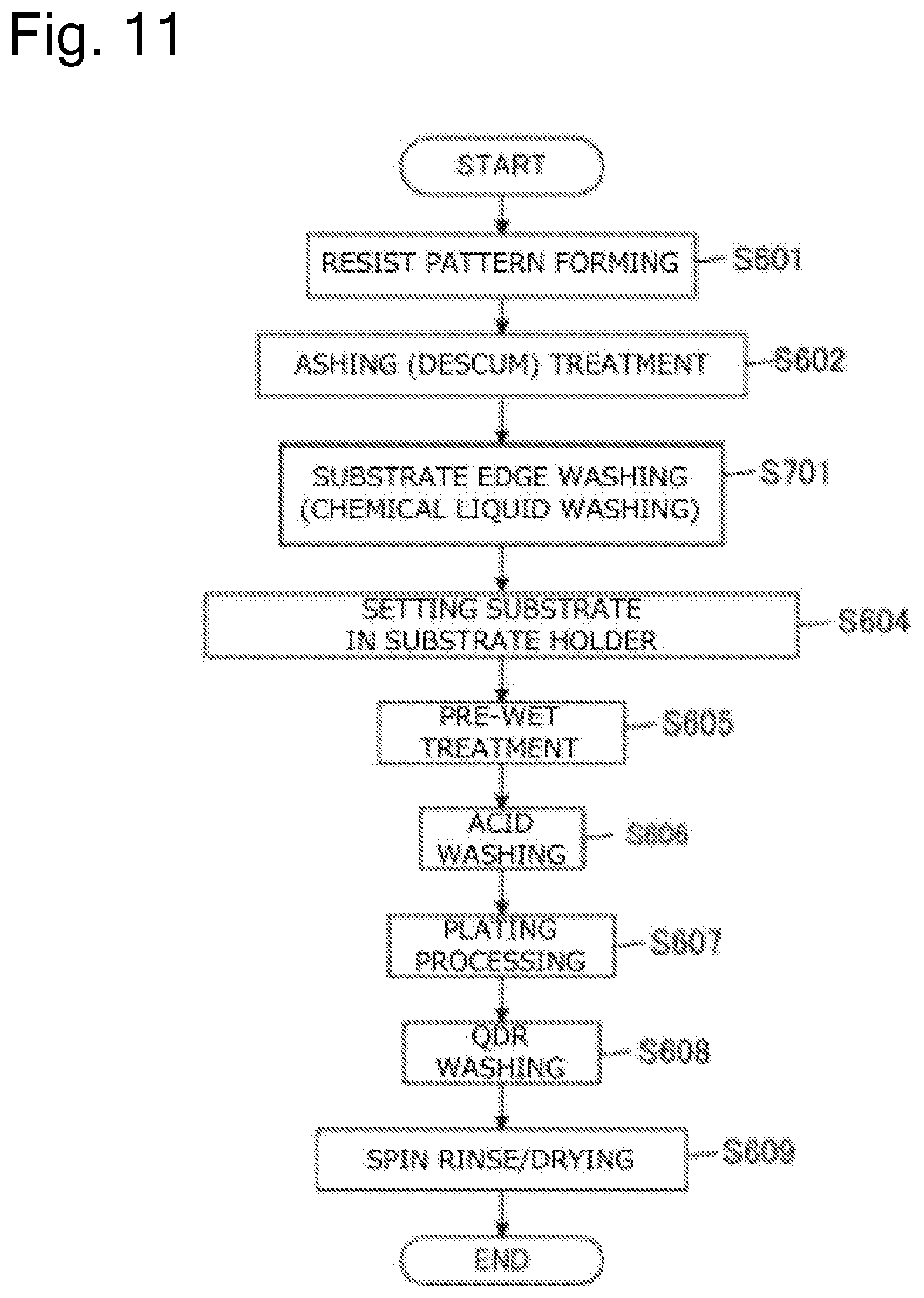
[0080] FIG. 11 is a flow chart illustrating a plating method according to the second embodiment.
[0081] FIG. 12 is an overall schematic representation of a plating apparatus according to a third embodiment.
[0082] FIG. 13 is a flow chart illustrating a plating method according to the third embodiment.
[0083] FIG. 14 is an overall schematic representation of a plating apparatus according to a fourth embodiment.
[0084] FIG. 15 is a schematic side view of a sponge washing device.
[0085] FIG. 16 is a flow chart illustrating a plating method according to the fourth embodiment.
[0086] FIG. 17 is an overall schematic representation of a plating apparatus according to a fifth embodiment.
[0087] FIG. 18 is a schematic side view of a sponge chemical liquid washing device.
[0088] FIG. 19 is a flow chart illustrating a plating method according to the fifth embodiment.
[0089] FIG. 20 is an overall schematic representation of a plating apparatus according to a sixth embodiment.
[0090] FIG. 21 is a flow chart illustrating a plating method according to the sixth embodiment.
[0091] FIG. 22 is a schematic side view of an example of an organic substance desorption device provided at a fixing unit.
[0092] FIG. 23A is a plan view of the organic substance desorption device illustrating a process of desorbing an organic substance at an edge section of a rectangular substrate using the organic substance desorption device illustrated in FIG. 22.
[0093] FIG. 23B is a plan view of the organic substance desorption device illustrating a process of desorbing an organic substance at the edge section of the rectangular substrate using the organic substance desorption device illustrated in FIG. 22.
[0094] FIG. 23C is a plan view of the organic substance desorption device illustrating a process of desorbing an organic substance at the edge section of the rectangular substrate using the organic substance desorption device illustrated in FIG. 22.
[0095] FIG. 23D is a plan view of the organic substance desorption device illustrating a process of desorbing an organic substance at the edge section of the rectangular substrate using the organic substance desorption device illustrated in FIG. 22.
[0096] FIG. 23E is a plan view of the organic substance desorption device illustrating a process of desorbing an organic substance at the edge section of the rectangular substrate using the organic substance desorption device illustrated in FIG. 22.
[0097] FIG. 24 is a schematic side view of another example of the organic substance desorption device provided at the fixing unit.
[0098] FIG. 25A is a plan view of the organic substance desorption device illustrating a process of desorbing an organic substance at the edge section of the rectangular substrate using the organic substance desorption device illustrated in FIG. 24.
[0099] FIG. 25B is a plan view of the organic substance desorption device illustrating a process of desorbing an organic substance at the edge section of the rectangular substrate using the organic substance desorption device illustrated in FIG. 24.
[0100] FIG. 25C is a plan view of the organic substance desorption device illustrating a process of desorbing an organic substance at the edge section of the rectangular substrate using the organic substance desorption device illustrated in FIG. 24.
[0101] FIG. 25D is a plan view of the organic substance desorption device illustrating a process of desorbing an organic substance at the edge section of the rectangular substrate using the organic substance desorption device illustrated in FIG. 24.
[0102] FIG. 25E is a plan view of the organic substance desorption device illustrating a process of desorbing an organic substance at the edge section of the rectangular substrate using the organic substance desorption device illustrated in FIG. 24.
[0103] FIG. 26 is a schematic side view of another example of the organic substance desorption device provided at the fixing unit.
[0104] FIG. 27A is a plan view of the organic substance desorption device illustrating a process of desorbing an organic substance at the edge section of the rectangular substrate using the organic substance desorption device illustrated in FIG. 26.
[0105] FIG. 27B is a plan view of the organic substance desorption device illustrating a process of desorbing an organic substance at the edge section of the rectangular substrate using the organic substance desorption device illustrated in FIG. 26.
[0106] FIG. 27C is a plan view of the organic substance desorption device illustrating a process of desorbing an organic substance at the edge section of the rectangular substrate using the organic substance desorption device illustrated in FIG. 26.
[0107] FIG. 28 is a schematic side view of another example of the organic substance desorption device provided at the fixing unit.
[0108] FIG. 29A is a plan view of the organic substance desorption device illustrating a process of desorbing an organic substance at the edge section of the rectangular substrate using the organic substance desorption device illustrated in FIG. 28.
[0109] FIG. 29B is a plan view of the organic substance desorption device illustrating a process of desorbing an organic substance at the edge section of the rectangular substrate using the organic substance desorption device illustrated in FIG. 28.
[0110] FIG. 29C is a plan view of the organic substance desorption device illustrating a process of desorbing an organic substance at the edge section of the rectangular substrate using the organic substance desorption device illustrated in FIG. 28.
DESCRIPTION OF EMBODIMENTS
First Embodiment
[0111] Embodiments of the present invention will be described hereinbelow with reference to the drawings. In the drawings described below, the same or corresponding constituent elements are denoted by the same reference numerals with redundant explanations thereof omitted.
[0112] FIG. 1 is an overall schematic representation of a plating apparatus according to a first embodiment. As illustrated in FIG. 1, the plating apparatus is roughly divided into a load/unload unit 170A for loading a substrate in a substrate holder 60 or unloads the substrate from the substrate holder 60 and a processing unit 170B for processing the substrate.
[0113] The load/unload unit 170A includes three front-opening unified pods (FOUPs) 102, an aligner 40 configured to adjust a position of an orientation flat, a notch, and the like of the substrate in a predetermined direction, and a spin rinse dryer 20 configured to rotate the substrate at a high speed to dry the substrate. The FOUP 102 is configured to accommodate a plurality of substrates such as a semiconductor wafer in multiple stages. A fixing unit 120 is provided near the spin rinse dryer 20. The fixing unit 120 is configured to place the substrate holder 60 thereon for attachment and removal of the substrate. A substrate conveyance device 122 is arranged at the center of these units 102, 40, 20, and 120. The substrate conveyance device 122 comprises a transfer robot that conveys the substrate among these units. As will be described later, the aligner 40 according to the first embodiment includes an organic substance desorption device (see FIGS. 4, 6, etc.) that is configured to locally desorb an organic substance existing at the edge section of the substrate before the substrate is set in the substrate holder 60.
[0114] The fixing unit 120 is configured to be able to place two substrate holders 60 thereon. In the fixing unit 120, the substrate is delivered between one substrate holder 60 and the substrate conveyance device 122, and then the substrate is delivered between the other substrate holder 60 and the substrate conveyance device 122.
[0115] The processing unit 170B of the plating apparatus has a stocker 124, a pre-wet bath 126, a pre-soak bath 128, a first washing bath 130a, a blow bath 132, a second washing bath 130b, and a plating bath 10. The stocker 124 is adapted for storage and temporary provisional custody of the substrate holder 60. In the pre-wet bath 126, the substrate is immersed in pure water. In the pre-soak bath 128, the oxide film on the surface of the conductive layer such as a seed layer formed on the surface of the substrate is etched away. In the first washing bath 130a, the substrate after the pre-soaking is washed along with the substrate holder 60 with a washing liquid (pure water or the like). In the blow bath 132, draining of the substrate after the washing is performed. In the second washing bath 130b, the substrate that has been subjected to the plating is washed with a washing solution along with the substrate holder 60. The stocker 124, the pre-wet bath 126, the pre-soak bath 128, the first washing bath 130a, the blow bath 132, the second washing bath 130b, and the plating bath 10 are arranged in this order.
[0116] The plating bath 10 has, for example, a plurality of plating cells 134 provided with an overflow bath. Each of the plating cells 134 accommodates one substrate therein and immerses the substrate in the plating solution held therein. By applying a voltage between the substrate and the anode in the plating cell 134, plating such as copper plating or the like is performed on the substrate surface.
[0117] The plating apparatus has a substrate holder conveyance device 140 adopting, for example, a linear motor system. The substrate holder conveyance device 140 is located on the side of each of these devices and configured to convey the substrate holder 60 together with the substrate among these devices. This substrate holder conveyance device 140 has a first transporter 142 and a second transporter 144. The first transporter 142 is configured to convey a substrate among the fixing unit 120, the stocker 124, the pre-wet bath 126, the pre-soak bath 128, the first washing bath 130a, and the blow bath 132. The second transporter 144 is configured to convey the substrate among the first washing bath 130a, the second washing bath 130b, the blow bath 132, and the plating bath 10. In another embodiment, the plating apparatus may include only either of the first transporter 142 and the second transporter 144, where the one transporter conveys the substrate among the fixing unit 120, the stocker 124, the pre-wet bath 126, the pre-soak bath 128, the first washing bath 130a, the second washing bath 130b, the blow bath 132, and the plating bath 10.
[0118] FIG. 2 is a perspective view of the substrate holder 60 used in the plating apparatus illustrated in FIG. 1. As illustrated in FIG. 2, the substrate holder 60 includes a first holding member 65 made of, for example, vinyl chloride and having a rectangular flat plate shape, and a second holding member 66 that is attached to the first holding member 65 via a hinge 63 so as to be opened and closed. A holding surface 68 for holding the substrate is provided substantially at the center of the first holding member 65 of the substrate holder 60. In addition, on the outer side of the holding surface 68 of the first holding member 65, an inversed L-shaped clamper 67 having a projecting portion projecting inward is provided along the circumference of the holding surface 68.
[0119] A pair of substantially T-shaped hands 69 serving as support portions for conveying the substrate holder 60 and suspending and supporting the substrate holder 60 are connected to an end of the first holding member 65 of the substrate holder 60. Inside the stocker 124 illustrated in FIG. 1, the hand 69 is hooked on the upper surface of the peripheral wall of the stocker 124 and thus the substrate holder 60 is vertically suspended and supported. Further, the hand 69 of the suspended and supported substrate holder 60 is grasped by the first transporter 142 or the second transporter 144, and thus the substrate holder 60 is conveyed. Also, in the pre-wet bath 126, the pre-soak bath 128, the washing baths 130a, 130b, the blow bath 132, and the plating bath 10, the substrate holder 60 is suspended and supported on the peripheral walls thereof via the hand 69.
[0120] In addition, the hand 69 includes an external contact (not shown) for connecting to an external power supply unit. This external contact is electrically connected to a plurality of electrical conductors 73 (see FIG. 3) provided on the outer periphery of the holding surface 68 via a plurality of wires.
[0121] The second holding member 66 includes a base portion 61 fixed to the hinge 63 and a ring-shaped seal holder 62 fixed to the base portion 61. A retaining ring 64 for pressing and fixing the seal holder 62 against the first holding member 65 is rotatably mounted on the seal holder 62 of the second holding member 66. The retaining ring 64 has a plurality of protrusions 64a protruding outward at the outer circumferential portion thereof. The upper surface of the protrusion 64a and the lower surface of the inward protruding portion of the clamper 67 have tapered surfaces inclined in opposite directions along the rotational direction.
[0122] When holding the substrate, the substrate is first placed on the holding surface 68 of the first holding member 65 with the second holding member 66 opened, and the second holding member 66 is closed. Subsequently, the retaining ring 64 is rotated in the clockwise direction, and the protrusion 64a of the retaining ring 64 is slid into the inside (lower side) of the inward projecting portion of the clamper 67. As a result, the first holding member 65 and the second holding member 66 are tightened and locked to each other via the tapered surfaces provided on the retaining ring 64 and the clamper 67, respectively, and the substrate is held. When taking the substrate out of the held state, the retaining ring 64 is rotated counterclockwise in a state where the first holding member 65 and the second holding member 66 are locked. As a result, the protrusion 64a of the retaining ring 64 is detached from the inverted L-shaped clamper 67, and the substrate is taken out of the held state.
[0123] FIG. 3 is a cross-sectional view illustrating an electrical contact of the substrate holder 60 illustrated in FIG. 2. As illustrated in FIG. 3, the substrate W is placed on the holding surface 68 of the first holding member 65. A plurality of (one in the figure) electrical conductors 73 connected to a plurality of wires extending from an external contact provided in the hand 69 illustrated in FIG. 2 are arranged between the holding surface 68 and the first holding member 65. The electrical conductors 73 are arranged on the outer side of the circumference of the substrate W so as to be exposed in the state in which the end portion of the electrical conductor 73 exhibits a spring characteristic on the surface of the first holding member 65 on the side of the substrate W when the substrate W is placed on the holding surface 68 of the first holding member 65.
[0124] A seal member 70 which is pressed against the outer peripheral surface of the substrate W and the first holding member 65 when the substrate W is held by the substrate holder 60 is attached to the surface (lower surface in the drawing) of the seal holder 62 facing the first holding member 65. The seal member 70 has a lip portion 70a for sealing the surface of the substrate W and a lip portion 70b for sealing the surface of the first holding member 65.
[0125] A support 71 is attached to the inside of the seal member 70 sandwiched between the pair of lips 70a, 70b. A plurality of electrical contacts 72 that are configured to be able to receive power from the electrical conductor 73 is fixed to the support 71, for example, using screws or the like, and are arranged along the circumference of the substrate W. The electrical contact 72 has an electrical contact end 72a extending inwardly of the holding surface 68 and a leg portion 72b configured to receive electricity from the electrical conductor 73.
[0126] When the first holding member 65 and the second holding member 66 illustrated in FIG. 2 are locked, then, as illustrated in FIG. 3, the short lip portion 70a on the inner peripheral surface side of the seal member 70 is pressed against the surface of the substrate W, and the long lip portion 70b on the outer peripheral surface side is pressed against the surface of the first holding member 65. As a result, the lip portion 70a and the lip portion 70b are reliably sealed and the substrate W is held.
[0127] In a region sealed by the seal member 70, that is, in a region sandwiched between the pair of lips 70a, 70b of the seal member 70, the electrical conductor 73 is electrically connected to the leg portion 72b of the electrical contact 72, and the electrical contact end 72a contacts the seed layer on the edge section of the substrate W. Thus, while the substrate W is sealed by the seal member 70 and held by the substrate holder 60, power can be supplied to the substrate W via the electrical contact 72.
[0128] As described above, a resist pattern is formed in advance on the substrate W on which the seed layer is formed. Before being conveyed to the plating apparatus illustrated in FIG. 1, the substrate W is irradiated with a UV or the like to remove the resist residue on the substrate surface (ashing treatment) and hydrophilization treatment (descum treatment) is performed thereon. The substrate W that has been subjected to the ashing and descum treatments is thereafter conveyed to the plating apparatus and held by the substrate holder 60. Here, an oxide film may be created on the seed layer on the edge section on which the resist of the substrate W is not applied, or organic substances volatilized from the resist may adhere to it due to passage of time after the ashing and descum treatments. As illustrated in FIG. 3, the electrical contact 72 contacts the edge section of the substrate W. Accordingly, when an oxide film is created on the seed layer at the edge section of the substrate W or organic substances adhere thereto, the contact resistance of the electrical contact 72 of the substrate holder 60 may problematically vary, causing deterioration of the uniformity of the plated film thickness.
[0129] In view of this, according to this embodiment, the organic substance desorption device is provided at the aligner 40 illustrated in FIG. 1, and organic substances created in the seed layer on the edge section of the substrate W are desorbed (removed). Note that, in this specification, the edge section of the substrate W refers to a region where the substrate W can be brought into contact with the electrical contact 72, or a region closer to the peripheral portion side of the substrate W than the portion where the seal member 70 is in contact when the substrate W is held by the substrate holder 60. For example, in this embodiment, it refers to a region on the outer peripheral side of a portion where the lip portion 70a of the seal member 70 illustrated in FIG. 3 abuts, and within a range of about 5 millimeters, and more preferably within the range of about 2 mm, from the outer peripheral portion of the substrate W toward the substrate center.
[0130] FIG. 4 is a schematic top view of the aligner 40 illustrated in FIG. 1. FIG. 5 is a schematic cross-sectional view of the aligner 40 in the direction of the arrow 5-5 illustrated in FIG. 4, and FIG. 6 is a schematic cross-sectional view of the aligner 40 in the direction of the arrow 6-6 illustrated in FIG. 4. As illustrated in FIGS. 4 to 6, the aligner 40 includes a base 41, a rotating stage 42, an aligner light source 43, a photodetector 44, and an organic substance desorption device 45 (corresponding to an example of the edge section washing device).
[0131] The rotating stage 42 is configured to stick to the back surface of the substrate W to rotate the substrate W in the circumferential direction. The rotating stage 42 sticks to the substrate W by an electrostatic adsorption or vacuum adsorption. The aligner light source 43 is configured to irradiate with light 46 the edge section or a region near the edge section of the substrate W rotated by the rotating stage 42. When the substrate W is rotated and the notch of the substrate W is moved to a position where it is irradiated with the light 46 from the aligner light source 43, the light 46 passes through the notch and reaches the photodetector 44. When the photodetector 44 has detected the light 46, the aligner 40 can recognize that the notch of the substrate W is positioned directly below the aligner light source 43, so that the orientation of the substrate W can be adjusted.
[0132] The organic substance desorption device 45 is a UV irradiation device or a plasma emission device. In this embodiment, a UV or plasma can be locally applied to the edge section of the substrate W from above the substrate W. The organic substance desorption device 45 can locally apply the UV or plasma to the edge section of the substrate W before the substrate W is held by the substrate holder 60. In other words, the area other than the edge section of the substrate W is not exposed to the UV or plasma. By rotating the substrate W by the rotating stage 42, the UV or plasma can be efficiently applied over the entire periphery of the edge section of the substrate W. When the organic substance adhering to the edge section of the substrate W is irradiated with the UV or plasma, the organic substance is decomposed to generate a volatile substance, and the organic substance that has become the volatile substance is volatilized and removed. It is preferable that the distance between the UV irradiation source of the UV irradiation device or the plasma emission port of the plasma emission device and the substrate W is about 1 mm or more and about 10 mm or less. If this distance is less than 1 mm, there is a possibility that the substrate and the UV irradiation source or the plasma emission port of the plasma emission device are in physical contact with each other. Also, if this distance is over 10 mm, the UV or plasma may not be radiated locally. In order to ensure that the substrate and the UV irradiation source or the plasma emission port of the plasma emission device are not brought into physical contact with each other and to enable local irradiation, it is more preferable that this distance be about 2 mm or more and about 5 mm or less.
[0133] For example, a high-pressure mercury lamp, a low-pressure mercury lamp, a black light, a laser light source capable of emitting light in the UV region, or the like can be adopted as the UV light source if the organic substance desorption device 45 is a UV irradiation device. Since a high-pressure mercury lamp, low-pressure mercury lamp, and black light have light divergence tendency, it is preferable when adopting any of these light sources that the light source is placed in the vicinity of the substrate W or only the edge section is irradiated with the UV using an optical system. If the organic substance desorption device 45 is a plasma emission device, for example, an atmospheric remote plasma device or the like can be adopted.
[0134] The aligner 40 may further include a sensor (spectrophotometer) configured to measure the absorbance by irradiating the edge section of the substrate W with a light in the ultraviolet region (200 nm to 380 nm), for example, a light having a wavelength of 365 nm as excitation light from above the edge section of the substrate W and observing a reflected light from the edge section, or may further include a sensor (fluorescent reflection film thickness meter) configured to monitor the intensity of a reflected light by irradiating it with a light in the fluorescent region.
[0135] This sensor (not shown) may be provided in the organic substance desorption device 45 or separately provided in the aligner 40. The control unit of the plating apparatus according to this embodiment is configured to be capable of determining whether or not the contaminant (including the organic substances and the oxide film) at the edge section have been sufficiently removed according to whether or not the value of the absorbance or the fluorescence intensity measured by this sensor is larger than a preset threshold value. For example, when it is determined that the contaminants at the edge section have not been sufficiently removed, the organic substance desorption device 45 may repeat the process of locally emitting the UV or plasma to the edge section of the substrate W. Also, if it is determined that the contaminants at the edge section have been sufficiently removed, then desorption of the organic substance is regarded as being completed and the substrate W is conveyed to the fixing unit 120 by the substrate conveyance device 122, which is followed by a series of plating processes. In this way, whether or not contaminants are present at the edge section of the substrate W is determined before the plating process, and thereafter, the plating process is performed on the substrate on which the contaminants do not remain at the edge section, so that deterioration of in-plane uniformity of plating film thickness of the substrate W due to variations in contact resistance of the electrical contact of the substrate holder 60, and the like can be more reliably prevented.
[0136] FIG. 7 is a flow chart illustrating a plating method according to the first embodiment. In this plating method, first, a resist pattern is formed on the substrate W before conveying the substrate W to the plating apparatus illustrated in FIG. 1 (step S601). Subsequently, UV irradiation is performed on the substrate W on which the resist pattern has been formed, resist residues on the surface of the substrate W are removed (ashing treatment), and a hydrophilization process (descum treatment) of the resist surface is performed (step S602). The processes in the steps S601 and S602 are performed in an appropriate device or devices other than the plating apparatus illustrated in FIG. 1.
[0137] Subsequently, the substrate W is conveyed from the FOUP 102 in which the substrate W has been accommodated to the aligner 40 by the substrate conveyance device 122. In the aligner 40, the edge section of the substrate W is washed (step S603). Specifically, in the aligner 40, a UV or plasma is locally applied to the edge section of the substrate W by the organic substance desorption device 45, and the organic substance is desorbed. At this point, the orientation of the substrate W is adjusted by the aligner 40.
[0138] Although not described in the flow illustrated in FIG. 7, if a sensor (not shown) is provided in the aligner 40, at least either of the organic substance and the oxide film present at the edge section of the substrate W is irradiated with a UV or plasma to locally remove the at least one of them, and then the presence or absence of the pollutants (including organic substances and oxide films) at the edge section can be confirmed. Specifically, first, the sensor (spectrophotometer or fluorescence reflection film thickness meter) is positioned above the surface of the substrate W arranged in the aligner 40. While the substrate W is rotated or stopped by the aligner 40, the sensor is made to scan the substrate from the central portion to the edge section thereof (or from the edge section to the central portion of the substrate), and the surface of the substrate W is irradiated with a light in the ultraviolet region (200 nm to 380 nm), for example, a light having a wavelength of 365 nm as excitation light from the sensor toward the surface of the substrate W, and absorbance or fluorescence intensity is measured.
[0139] The edge section that has been subjected to the UV or plasma treatment and a plated surface that is not subjected to the UV or plasma treatment exist on the surface of the substrate, and the seed layer is formed on the entire surface of the substrate surface (the plated surface and the edge section). The absorbance or the fluorescence intensity of both the plated surface and the edge section can be measured by scanning the plated surface and the edge section using the sensor. The control unit of the plating apparatus compares, for example, the absorbances of both the plated surface and the edge section, and whether or not contaminants (including the organic substances and the oxide film) in the edge section have been sufficiently removed can be determined, for example, according to whether or not the value of the ratio of the absorbance at the edge section to the absorbance at the plated surface exceeds a preset threshold value (for example, 50% or less). When the value of the ratio is larger than the threshold value, it can be determined that the contaminants (including the organic substance and the oxide film) at the edge section are not sufficiently removed. Also, when the value of the ratio is not larger than the threshold value, it can be determined that the contaminants (including the organic substances and the oxide film) at the edge section have been sufficiently removed. In the case of measuring the fluorescence intensity as well, whether or not contaminants at the edge section of the substance have been sufficiently removed can be determined by comparing the predetermined threshold value and the measured value in the same manner.
[0140] Based on this determination, if it is determined that the contaminants at the edge section are not sufficiently removed, the process of locally radiating the UV or plasma to the edge section of the substrate W may be repeated. If it is determined that the contaminants at the edge section have been sufficiently removed, desorption of the organic substance is regarded as completed, the substrate is conveyed to the fixing unit 120 by the substrate conveyance device 122, which is followed by a series of plating processes. In this way, whether or not contaminants are present at the edge section of the substrate W is determined before the plating process, and thereafter, the plating process is performed on the substrate on which the contaminants do not remain at the edge section and deterioration of in-plane uniformity of plating film thickness of the substrate W due to variations in contact resistance of the electrical contacts of the substrate holder 60, and the like can be more reliably prevented.
[0141] The substrate W whose edge section has been washed is conveyed to the fixing unit 120 by the substrate conveyance device 122 and set in the substrate holder 60 (step S604). At this point, since the organic substance at the edge section of the substrate W is desorbed, the electrical contact of the substrate holder 60 is brought into contact with the edge section of the washed substrate W. This makes it possible to reduce variations in the contact resistance of the electrical contact of the substrate holder 60 due to the adhesion of organic substances.
[0142] The substrate W held by the substrate holder 60 is first conveyed to the pre-wet bath 126 by the substrate holder conveyance device 140, and the substrate W is immersed in the pure water contained in the pre-wet bath 126 (step S605). Subsequently, the substrate W is conveyed to the pre-soak bath 128, and the surface of the substrate W is acid-washed (step S606). Specifically, the substrate W is immersed in a chemical liquid such as sulfuric acid, nitric acid or the like contained in the pre-soak bath 128, and the oxide film on the surface of the seed layer formed on the surface of the substrate is removed by etching.
[0143] Although not described in the flow illustrated in FIG. 7, even when the acid-washed substrate W may be immersed in the pure water contained in the first washing bath 130a and the chemical liquid attached to the surface of the substrate W may be washed. Subsequently, the substrate W is immersed in one of the plating cells 134 of the plating bath 10, and a plating process is performed (step S607). Quick damp rinse (QDR) treatment is performed on the substrate W on which the plating film is formed on the surface (step S608). Specifically, the substrate W is immersed in the pure water contained in the second washing bath 130b and the plating solution attached to the surface of the substrate W is washed.
[0144] Subsequently, the substrate W held by the substrate holder 60 is conveyed to the fixing unit 120, and the substrate W is detached from the substrate holder 60. The substrate conveyance device 122 receives the substrate W from the fixing unit 120 and conveys the substrate W to the spin rinse dryer 20. The surface of the substrate W is washed and dried in the spin rinse dryer 20 (step S609).
[0145] As described above, according to this embodiment, it is made possible to locally remove the organic substances present in the edge section of the substrate W before the substrate is set in the substrate holder 60. Accordingly, it is made possible to suppress variations in the contact resistance of the electrical contact 72 of the substrate holder 60 due to the organic substance present at the edge section of the substrate W without adversely affecting the resist pattern formed on the surface of the substrate W, and prevent deterioration of the uniformity of the plated film thickness.
[0146] Also, according to this embodiment, a UV or plasma can be locally emitted to the edge section of the substrate W. By virtue of this, no UV or plasma is radiated to the surface other than the edge section of the substrate W, i.e., the portion on the substrate W where the resist is applied, so that the organic substance on the edge section of the substrate W can be desorbed.
[0147] Further, according to this embodiment, since the organic substance desorption device 45 is provided at the aligner 40, the edge section of the substrate W can be processed by the UV irradiation device or the plasma emission device while the substrate is rotated by the aligner 40. Accordingly, it is not necessary to provide a mechanism for rotating the substrate in the organic substance desorption device 45, so that the cost can be reduced. Further, by providing the organic substance desorption device 45 in the aligner 40, it is made possible to reduce the footprint of the plating apparatus as a whole.
[0148] Note that the organic substance desorption device 45 may be provided in the plating apparatus separately from the aligner 40. FIG. 8 is an overall schematic representation of another example of the plating apparatus according to the first embodiment. As illustrated in FIG. 8, the organic substance desorption device 45 is provided in the load/unload unit 170A separately from the aligner 40. In this case, the aligner 40 will have a configuration corresponding to the configurations illustrated in FIGS. 4 to 6 except that the organic substance desorption device 45 is omitted therefrom. In the meantime, the organic substance desorption device 45 needs to have a mechanism similar to the rotating stage 42 illustrated in FIGS. 4 to 6 for rotating the substrate W. According to the plating apparatus illustrated in FIG. 8, since the organic substance desorption device 45 is provided separately from the aligner 40, the process or processes of the organic substance desorption device 45 and the process or processes of the aligner 40 can be separately performed from each other on multiple substrates W. As a result, in the case where the throughput of the entire processes is determined by the treatment time of the organic substance desorption treatment because the organic substance desorption treatment takes time, the throughput can be made higher than that of the plating apparatus illustrated in FIG. 1. It may be noted here that the organic substance desorption device 45 can also be provided at the spin rinse dryer 20. Even in this case, the spin rinse dryer 20 may include a sensor (spectrophotometer) configured to measure the absorbance or a sensor (fluorescence reflection film thickness meter) configured to monitor the intensity of a reflected light by radiating a light in the fluorescent region and monitor the intensity of the reflected light (not shown). In that case, the sensor is positioned above the edge section of the substrate W during or after the washing of the edge section. Then, the substrate W is rotated, a light is radiated from the sensor to the edge section of the substrate W, a light reflected from the substrate W is received by the light receiving portion of the sensor, and the fluorescence intensity or absorbance of the reflected light is measured. Thus, it may be determined whether or not the contaminants (at least either of the organic substance and the oxide film) at the edge section of the substrate W have been sufficiently removed. By such a configuration, whether or not contaminants are present on the edge section of the substrate W is determined before performing the plating process, and thereafter the plating process can be performed on the substrate on which no contaminants remain at the edge section, so that deterioration of in-plane uniformity of plating film thickness of the substrate W due to variations in contact resistance of the electrical contact of the substrate holder 60, and the like can be more reliably prevented. If the apparatus is configured to determine whether or not a contaminant is present at the edge section of the substrate W during the washing of the edge section of the substrate W, the end point of the washing may be determined based on the determination result of this sensor.
Second Embodiment
[0149] FIG. 9 is an overall schematic representation of the plating apparatus according to a second embodiment. The second embodiment differs from the plating apparatus illustrated in FIG. 1 of the first embodiment in the features of the spin rinse dryer 20 and the aligner 40. Since other features are similar to those of the first embodiment, the same reference numerals are given to the same features as those of the first embodiment, and explanations thereof are omitted.
[0150] In the second embodiment, the aligner 40 does not include the organic substance desorption device 45 described in the first embodiment. In addition, the spin rinse dryer 20 has an oxide film removal device configured to locally remove the oxide film present at the edge section of the substrate before the substrate is set in the substrate holder 60.
[0151] FIG. 10 is a schematic diagram illustrating the spin rinse dryer 20 that includes the oxide film removal device. As illustrated in the figure, the spin rinse dryer 20 has a rotating stage 21, a substrate chuck 22, a DIW nozzle 23, and the oxide film removal device 24 (corresponding to an example of the edge section washing device). The substrate chuck 22 is configured to grasp the outer peripheral portion of the substrate W. The rotating stage 21 is configured to rotate the substrate chuck 22, and rotates the grasped substrate W in the circumferential direction as the substrate chuck 22 rotates. The DIW nozzle 23 is configured to supply deionized water (DIW) to a substantially central portion of the substrate W. The DIW supplied to the substrate W receives the centrifugal force by the rotation of the substrate W and flows toward the outer peripheral portion of the substrate W. Although not shown, the spin rinse dryer 20 has a cover that covers the periphery of the substrate W so as to prevent the DIW of the substrate W from scattering to the outside.
[0152] The oxide film removal device 24 is a chemical liquid supply device configured to supply a chemical liquid 28 to the substrate, and includes a chemical liquid nozzle 25 configured to supply the chemical liquid 28, an arm 26 connected to the chemical liquid nozzle 25, and a rotation shaft 27 configured to cause the arm 26 to pivot. It is preferable that the distance between the tip of the chemical liquid nozzle 25 and the substrate W is about 1 mm or more and about 10 mm or less. If the distance is less than 1 mm, there is a possibility that the substrate and the chemical liquid nozzle 25 physically contact each other. Also, if this distance is over 10 mm, there is a possibility that the chemical liquid cannot be supplied locally. In order to ensure that the substrate and the chemical liquid nozzle 25 are not brought into physical contact with each other and enable local supply of the chemical liquid, it is more preferable that the distance between the tip of the chemical liquid nozzle 25 and the substrate is set to about 2 mm or more and about 5 mm or less.
[0153] In order to locally remove the oxide film present at the edge section of the substrate W by the oxide film removal device 24, first, the oxide film removal device 24 causes the arm 26 to pivot according to the diameter of the substrate W, and the chemical liquid nozzle 25 is positioned above the edge section of the substrate W. In the state where the chemical liquid nozzle 25 is positioned above the edge section of the substrate W, the DIW is supplied from the DIW nozzle 23 to the substantially central portion of the rotating substrate W, and the chemical liquid 28 is ejected to the edge section of the rotating substrate W. The chemical liquid 28 is supplied to the edge section of the substrate W and flows toward the outer peripheral portion of the substrate W under the centrifugal force due to the rotation of the substrate W. Thereby, the oxide film removal device 24 can supply the chemical liquid 28 locally to the edge section of the substrate W. In other words, the regions other than the edge section of the substrate W are substantially not exposed to the chemical liquid 28. By rotating the substrate W by the rotating stage 21, the chemical liquid 28 can be efficiently supplied over the entire periphery of the edge section of the substrate W. When the chemical liquid 28 is supplied to the oxide film created at the edge section of the substrate W, the oxide film is dissolved and removed by the chemical liquid 28. After supplying the chemical liquid 28 for a predetermined time, the supply of the chemical liquid 28 is stopped while the supply of the DIW is continued. As a result, the chemical liquid 28 supplied to the edge section of the substrate W is washed off. Here, the edge section of the substrate W refers, as mentioned in the foregoing, to an area where the electrical contact 72 can be brought into contact with the edge section of the substrate W, or a region closer to the peripheral portion side of the substrate W than the portion where the substrate W is in contact with the seal member 70 when the substrate W is held by the substrate holder 60. Meanwhile, the apparatus may also be configured such that, assuming in advance that some of the chemical liquid can be scattered when supplying the chemical liquid to the substrate in a spotwise manner, the chemical liquid components and concentration are specified such that the chemical liquid is unlikely to adversely affect the resist pattern, and the oxide film in the peripheral portion of the edge section of the substrate W is dissolved and removed by the chemical liquid 28.
[0154] An acid such as dilute sulfuric acid, citric acid or the like, which is unlikely to damage the seed layer on the substrate W, can be adopted as the chemical liquid 28. In this embodiment, it is preferable that the chemical liquid 28 is 3 wt % or more and 15 wt % or less of diluted sulfuric acid or 2 wt % or more and 20 wt % or less of citric acid. If diluted sulfuric acid is less than 3 wt % or citric acid is less than 2 wt %, there is a possibility that the acid concentration is too low to properly remove the oxide film. Also, if the diluted sulfuric acid exceeds 15 wt % or citric acid exceeds 20 wt %, the acid concentration is too high and there is a possibility that the seed layer on the edge section of the substrate is melted.
[0155] FIG. 11 is a flow chart that illustrates a plating method according to the second embodiment. The plating method according to the second embodiment coincides in many aspects with the plating method illustrated in FIG. 7 except for some aspects. Accordingly, explanations of the same parts as those of the plating method of FIG. 7 will be partly omitted.
[0156] The substrate W subjected to the ashing treatment and the descum treatment in step S602 is conveyed to the plating apparatus illustrated in FIG. 9. Subsequently, the substrate W is conveyed from the FOUP 102 in which the substrate W has been accommodated to the spin rinse dryer 20 by the substrate conveyance device 122. In the spin rinse dryer 20, washing of the edge section of the substrate W is performed (step S701). Specifically, in the spin rinse dryer 20, the oxide film present at the edge section of the substrate W is removed by the oxide film removal device 24.
[0157] Further, also in this embodiment, in order to measure the state of the edge section of the substrate W, the spin rinse dryer 20 may include a sensor (spectrophotometer) configured to measure the absorbance of the edge section by irradiating the edge section with a light in the ultraviolet region (200 nm to 380 nm), for example, a light having a wavelength of 365 nm as excitation light from above the edge section of the substrate W or a sensor (fluorescent reflection film thickness meter) configured to monitor the intensity of a reflected light by irradiating it with a light in the fluorescent region (not shown). In that case, the sensor is positioned above the edge section of the substrate W during or after the washing of the edge section. Then, the substrate W is rotated, a light is radiated from the sensor to the edge section of the substrate W, a light reflected from the substrate W is received by the light receiving portion of the sensor, and the fluorescence intensity or absorbance of the reflected light is measured. Thereby whether or not the oxide film at the edge section of the substrate W has been sufficiently removed may be determined to inspect the state of the edge section. By such a configuration, whether or not contaminants are present on the edge section of the substrate W is determined before performing the plating process, and thereafter the plating process can be performed on the substrate on which no contaminants remain at the edge section, so that deterioration of in-plane uniformity of plating film thickness of the substrate W due to variations in contact resistance of the electrical contact of the substrate holder 60, and the like can be more reliably prevented.
[0158] The substrate W which has been subjected to the washing (in some cases washing and inspection) of the edge section is conveyed to the fixing unit 120 by the substrate conveyance device 122 and set in the substrate holder 60 (step S604). At this point, since the oxide film at the edge section of the substrate W has been removed, the electrical contact of the substrate holder 60 is brought into contact with the edge section of the washed substrate W. This makes it possible to reduce variations in the contact resistance of the electrical contact of the substrate holder 60 caused by the oxide film. The substrate W set in the substrate holder 60 is processed in the subsequent steps S605 to S609.
[0159] As described above, according to the second embodiment, it is made possible to locally remove the oxide film present at the edge section of the substrate before the substrate is set in the substrate holder 60. Accordingly, it is made possible to suppress variations in the contact resistance of the electrical contact 72 of the substrate holder 60 due to the oxide film existing at the edge section of the substrate W, without adversely affecting the resist pattern formed on the surface of the substrate W, and prevent deterioration of uniformity of the plating film thickness.
[0160] In addition, according to the second embodiment, since the oxide film removal device 24 is provided at the spin rinse dryer 20, the edge section of the substrate W can be processed with the chemical liquid 28 while rotating the substrate by the spin rinse dryer 20. Accordingly, the oxide film removal device 24 does not need to include a mechanism for rotating the substrate and a mechanism for preventing scattering of the chemical liquid 28, so that the cost can be reduced. Also, since the spin rinse dryer 20 has a cover for preventing the liquid on the substrate W from scattering, the chemical liquid 28 supplied from the chemical liquid nozzle 25 can be prevented from scattering to the outside of the spin rinse dryer 20. Further, by providing the oxide film removal device 24 in the spin rinse dryer 20, it is made possible to reduce the footprint of the plating apparatus as a whole
[0161] Since the seed layer is formed on the substrate W to be plated, the seed layer may melt if the seed layer is unattended with the chemical liquid 28 attached to the seed layer. Accordingly, when the chemical liquid 28 adheres to a portion other than the edge of the substrate W to be plated, for example, the seed layer exposed via the opening of the resist pattern, sufficient washing is required so that the chemical liquid 28 does not remain there. According to the second embodiment, the chemical liquid 28 can be locally supplied to the edge section of the substrate W. This makes it possible to remove the oxide film created at the edge section of the substrate without letting the chemical liquid 28 adhere to the seed layer exposed via the opening of the resist pattern. Therefore, compared to the case where the chemical liquid 28 adheres to the entire surface of the substrate W, the washing time of the substrate W can be greatly shortened.
Third Embodiment
[0162] FIG. 12 is an overall schematic representation of a plating apparatus according to a third embodiment. The plating apparatus according to the third embodiment has a configuration in which the spin rinse dryer 20 in the plating apparatus illustrated in FIG. 8 according to the first embodiment is replaced with the spin rinse dryer 20 illustrated in FIG. 10 according to the second embodiment. Since the other features are the same as those of the plating apparatus illustrated in FIG. 8 of the first embodiment, the same reference numerals are given to the same features as those of the first embodiment, and explanations thereof will be omitted.
[0163] The plating apparatus illustrated in FIG. 12 includes the spin rinse dryer 20 having the oxide film removal device 24 illustrated in FIG. 10, and an organic substance desorption device 45. Therefore, the present plating apparatus can locally remove both the organic substance and the oxide film present at the edge section of the substrate W.
[0164] FIG. 13 is a flow chart illustrating a plating method according to the third embodiment. The plating method according to the third embodiment is a method obtained by combining the step S701 illustrated in FIG. 11 with the plating method illustrated in FIG. 7. Specifically, as illustrated in FIG. 13, the substrate W subjected to the ashing treatment and the descum treatment in the step S602 is conveyed to the plating apparatus illustrated in FIG. 11. Subsequently, the substrate W is conveyed from the FOUP 102 in which the substrate W has been accommodated to the aligner 40 by the substrate conveyance device 122. In the aligner 40, the edge section of the substrate W is washed (step S603). Specifically, in the aligner 40, the organic substance present at the edge section of the substrate W is desorbed by the organic substance desorption device 45. At this point, the orientation of the substrate W is adjusted by the aligner 40. Note that the edge section here refers to a region that is closer to the peripheral portion side of the substrate W than the portion where the seal member 70 is in contact when the substrate W is held by the substrate holder 60, which is, for example, within a range of about 5 mm, and more preferably within a range of about 2 mm, from the outer peripheral portion of the substrate W toward the substrate center.
[0165] Furthermore, also in this embodiment, in order to measure the state of the edge section of the substrate, the aligner 40 may include a sensor (spectrophotometer) configured to measure the absorbance of the edge section by irradiating the edge section of the substrate W with a light in the ultraviolet region (200 nm to 380 nm), for example, a light having a wavelength of 365 nm as excitation light from above the edge section or a sensor (fluorescent reflection film thickness meter) configured to monitor the intensity of a reflected light by irradiating it with a light in the fluorescent region (not shown). The control unit of the plating apparatus is configured to be capable of determining whether or not the contaminants (including the organic substance and the oxide film) of the edge section have been sufficiently removed according to whether or not the value of the absorbance or the fluorescence intensity measured by this sensor is larger than a preset threshold value. In that case, the sensor is positioned above the edge section of the substrate W during or after the washing of the edge section. Then, the substrate W is rotated, a light is radiated from the sensor to the edge section of the substrate W, a light reflected from the substrate W is received by the light receiving portion of the sensor, and the fluorescence intensity or absorbance of the reflected light is measured. Thus, the apparatus may be configured to determine whether or not contaminants (including organic substances and oxide films) at the edge section of the substrate W have been sufficiently removed and thereby determine whether or not contaminants are present at the edge section. By such a configuration, whether or not contaminants are present on the edge section of the substrate W is determined before performing the plating process, and thereafter the plating process can be performed on the substrate on which no contaminants remain at the edge section, so that it is made possible to prevent deterioration and the like of in-plane uniformity of the plating film thickness of the substrate W due to variations in contact resistance of electrical contact of the substrate holder 60. If the apparatus is configured to determine whether or not a contaminant is present at the edge section of the substrate W during the washing of the edge section of the substrate W, the end point of the washing may be determined based on the determination result of this sensor. Furthermore, the presence or absence of a substrate W which originally has an abnormality in the edge section can also be determined based on the measurement result of the sensor.
[0166] The substrate W from which the organic substances at the edge section have been desorbed is subsequently conveyed to the spin rinse dryer 20 by the substrate conveyance device 122. In the spin rinse dryer 20, washing of the edge section of the substrate W is performed (step S701). Specifically, in the spin rinse dryer 20, the oxide film existing at the edge section of the substrate W is desorbed by the oxide film removal device 24. Note that the edge section here refers to a region that is closer to the peripheral portion side of the substrate W than the portion where the seal member 70 is in contact when the substrate is held by the substrate holder and, for example, if the substrate W is a 300 mm wafer, within a range of about 5 mm, and more preferably within a range of about 2 mm, from the outer peripheral portion of the substrate W toward the substrate center, but it is also possible to specify the chemical liquid components and concentration such that the chemical liquid is unlikely to adversely affect the resist pattern, and dissolve and remove the oxide film existing at and near the edge section.
[0167] The substrate W whose edge section has been washed is conveyed to the fixing unit 120 by the substrate conveyance device 122 and set in the substrate holder 60 (step S604). At this point, since the organic substances and the oxide film at the edge section of the substrate W have been removed, the electrical contact of the substrate holder 60 is brought into contact with the edge section of the washed substrate W. This makes it possible to reduce variations in the contact resistance of the electrical contact of the substrate holder 60 due to the organic substance and the oxide film. The substrate W set in the substrate holder 60 is processed in the subsequent steps S605 to S609.
[0168] As explained above, according to the third embodiment, it is made possible to locally remove the organic substance and the oxide film present at the edge section of the substrate before the substrate is set in the substrate holder 60. Accordingly, it is made possible to suppress variations in the contact resistance of the electrical contact 72 of the substrate holder 60 due to the organic substance and the oxide film present at the edge section of the substrate W without adversely affecting the resist pattern formed on the surface of the substrate W, and prevent deterioration of the uniformity of the plated film thickness.
[0169] At the edge section of the substrate W, organic substances may adhere to the oxide film. Accordingly, when the oxide film is removed before desorbing the organic substance, it is difficult to remove the oxide film in the portion where the organic substances adhere. According to the third embodiment, since the oxide film is removed after desorption of the organic substance, the organic substances and the oxide film can be effectively removed. However, in one embodiment, the organic substance desorption process (step S603) may be performed after the chemical liquid washing of the edge section (step S701).
Fourth Embodiment
[0170] FIG. 14 is an overall schematic representation of a plating apparatus according to a fourth embodiment. The plating apparatus of the fourth embodiment differs from the plating apparatus of FIG. 1 according to the first embodiment in that it includes a sponge washing device 80 while it does not include the organic substance desorption device 45. Since other features are similar to those of the first embodiment, the same reference numerals are given to the same features as those of the first embodiment, and explanations thereof will be omitted.
[0171] The aligner 40 of the plating apparatus illustrated in FIG. 14 does not include the organic substance desorption device 45 described in the first embodiment. The sponge washing device 80 is provided in the load/unload unit 170A and configured to locally remove a particle or particles present at the edge section of the substrate W.
[0172] FIG. 15 is a schematic side view of the sponge washing device 80. As illustrated in the figure, the sponge washing device 80 has a rotation stage 81, a DIW nozzle 83, a sponge washing unit 84 (corresponding to an example of the edge section washing device), and a cover 88. The rotation stage 81 is configured to stick to the back surface of the substrate W to rotate the substrate W in the circumferential direction. The rotation stage 81 sticks to the substrate W by an electrostatic adsorption or vacuum adsorption. The DIW nozzle 83 is configured to supply DIW to a substantially central portion of the substrate W. The DIW supplied to the substrate W receives the centrifugal force by the rotation of the substrate W and flows toward the outer peripheral portion of the substrate W. The cover 88 covers the periphery of the substrate W and prevents the DIW of the substrate W from scattering to the outside.
[0173] The sponge washing unit 84 has a sponge head 85 configured to physically wash the edge section of the substrate W, an arm 86 connected to the sponge head 85, and a rotation shaft 87 configured to pivot the arm 86. The sponge head 85 is made of, for example, polyvinyl alcohol (PVA) and is configured to be rotatable about a vertical axis. Further, the rotation shaft 87 is configured to be expanded and contracted in an axial direction.
[0174] In order to locally remove the particles present at the edge section of the substrate W by the sponge washing unit 84, first, the sponge washing device 80 makes the arm 86 pivot according to the diameter of the substrate W, and the sponge head 85 is positioned above the edge section of the substrate W. In the state where the sponge head 85 is positioned above the edge section of the substrate W, the rotation shaft 87 contracts downward in the axial direction and the sponge head 85 is brought into abutment on the edge section of the substrate W. The sponge washing unit 84 rotates the sponge head 85 in the state where the sponge head 85 is in abutment on the edge section of the rotating substrate W. At this point, the DIW is supplied to the substrate W by the DIW nozzle 83. As a result, the sponge washing device 80 can locally remove the particles at the edge section of the substrate W. Also, a sensor (not shown) may be provided in the sponge washing device 80 to determine whether or not contaminants are present at the edge section.
[0175] FIG. 16 is a flow chart illustrating a plating method according to the fourth embodiment. The plating method according to the fourth embodiment has the step S801 in place of the step S603 in the plating method illustrated in FIG. 7 according to the first embodiment. Explanations of the same parts as those of the plating method of FIG. 7 will be partly omitted.
[0176] In the flow illustrated in FIG. 16, the substrate W subjected to the ashing and descum treatments in the step S602 is conveyed to the plating apparatus illustrated in FIG. 14. Subsequently, the substrate W is conveyed from the FOUP 102 in which the substrate W has been accommodated to the sponge washing device 80 by the substrate conveyance device 122. In the sponge washing device 80, the edge section of the substrate W is washed (step S801). Specifically, in the sponge washing device 80, the particles present at the edge section of the substrate W are removed by the sponge washing unit 84.
[0177] Also in this embodiment, in order to measure the state of the edge section of the substrate W, the sponge washing device 80 may include a sensor (spectrophotometer) configured to measure the absorbance of the edge section by irradiating the edge section with a light in the ultraviolet region (200 nm to 380 nm), for example, a light having a wavelength of 365 nm as excitation light from above the edge section of the substrate W or a sensor (fluorescent reflection film thickness meter) configured to monitor the intensity of a reflected light by irradiating it with a light in the fluorescent region (not shown). The control unit of the plating apparatus is configured to be capable of determining whether or not the contaminants (including the organic substance and the oxide film) of the edge section have been sufficiently removed according to whether or not the value of the absorbance or the fluorescence intensity measured by this sensor is larger than a preset threshold value. If the sensor is provided in the sponge washing device 80, the sensor is positioned above the edge section of the substrate W during or after washing of the edge section. Then, the substrate W is rotated, the presence or absence of particles at the edge section of the substrate W may be determined, and it may be determined whether or not a contaminant exists in the edge section. By such a configuration, whether or not contaminants are present at the edge section of the substrate W is determined before performing the plating process, and thereafter the plating process can be performed on the substrate on which no contaminants remain at the edge section, so that it is made possible to prevent deterioration and the like of in-plane uniformity of the plating film thickness of the substrate W due to variations in contact resistance of electrical contact of the substrate holder 60. Further, if the apparatus is configured to determine whether or not a contaminant is present at the edge section of the substrate W during the washing of the edge section of the substrate W, the end point of the washing may be determined based on the determination result of this sensor. Furthermore, the presence or absence of a substrate W which originally has an abnormality in the edge section can also be determined based on the measurement result of the sensor.
[0178] The substrate W whose edge section has been washed is conveyed to the fixing unit 120 by the substrate conveyance device 122 and set in the substrate holder 60 (step S604). At this point, since the particles at the edge section of the substrate W have been removed, the electrical contact of the substrate holder 60 is brought into contact with the edge section of the washed substrate W. This makes it possible to reduce variations in the contact resistance of the electrical contact of the substrate holder 60 caused by the particles. The substrate W set in the substrate holder 60 is processed in the subsequent steps S605 to S609.
[0179] As described above, according to the fourth embodiment, particles present at the edge section of the substrate W can be locally removed before the substrate is set in the substrate holder 60. Accordingly, it is made possible to prevent particles from being caught between the electrical contact of the substrate holder 60 and the seed layer on the edge section of the substrate W, and it is made possible to suppress deterioration of contact resistance due to particles.
Fifth Embodiment
[0180] FIG. 17 is an overall schematic representation of a plating apparatus according to a fifth embodiment. The plating apparatus of the fifth embodiment differs from the plating apparatus of FIG. 1 according to the first embodiment in that it includes a sponge chemical liquid washing device 90. Since other features are similar to those of the first embodiment, the same reference numerals are given to the same features as those of the first embodiment, and explanations thereof will be omitted.
[0181] The sponge chemical liquid washing device 90 illustrated in FIG. 17 is provided in the load/unload unit 170A and configured to locally remove the oxide film and particles present at the edge section of the substrate W. Although not illustrated in FIG. 17, the sponge chemical liquid washing device 90 may also include a sensor (not shown) above and near the edge section of the substrate W and may be configured to determine whether or not contaminants are present at the edge section. In this case, a sensor (spectrophotometer) may be provided which is configured to measure the absorbance of the edge section by irradiating the edge section with a light in the ultraviolet region (200 nm to 380 nm), for example, a light having a wavelength of 365 nm as excitation light from above the edge section of the substrate W or a sensor (fluorescent reflection film thickness meter) may be provided which is configured to monitor the intensity of a reflected light by irradiating it with a light in the fluorescent region (not shown). The control unit of the plating apparatus is configured to be capable of determining whether or not the contaminants (including the organic substance and the oxide film) of the edge section have been sufficiently removed according to whether or not the value of the absorbance or the fluorescence intensity measured by this sensor is larger than a preset threshold value.
[0182] FIG. 18 is a schematic side view of the sponge chemical liquid washing device 90. As illustrated in the figure, the sponge chemical liquid washing device 90 includes a rotation stage 91, a DIW nozzle 93, a sponge washing unit 84, an oxide film removal device 94 (corresponding to an example of the edge section washing device), and a cover 98. The rotation stage 91 is configured to stick to the back surface of the substrate W to rotate the substrate W in the circumferential direction. The rotation stage 91 sticks to the substrate W by an electrostatic adsorption or vacuum adsorption.
[0183] The oxide film removal device 94 is a chemical liquid supply device for supplying a chemical liquid to the substrate and includes a chemical liquid nozzle 95 configured to supply the chemical liquid, an arm 96 connected to the chemical liquid nozzle 95, and a rotation shaft 97 configured to pivot the arm 96. It is preferable that the distance between the tip of the chemical liquid nozzle 95 and the substrate W is about 1 mm or more and about 10 mm or less. If the distance is less than 1 mm, there is a possibility that the substrate and the chemical liquid nozzle 95 physically contact each other. Also, if this distance is over 10 mm, there is a possibility that the chemical liquid cannot be supplied locally. In order to ensure that the substrate and the chemical liquid nozzle 95 are not brought into physical contact with each other and to be able to supply the chemical liquid locally, the distance between the tip of the chemical liquid nozzle 95 and the substrate is set to about 2 mm or more and about 5 mm or less.
[0184] In order to locally remove the oxide film present at the edge section of the substrate W by the sponge chemical liquid washing device 90, first, the oxide film removal device 94 pivots the arm 96 according to the diameter of the substrate W, and the chemical liquid nozzle 95 is positioned above the edge section of the substrate W. In the state where the chemical liquid nozzle 95 is positioned above the edge section of the substrate W, the DIW is supplied from the DIW nozzle 93 to the substantially central portion of the rotating substrate W, and the chemical liquid is ejected to the edge section of the rotating substrate W. The chemical liquid is supplied to the edge section of the substrate W and flows toward the outer peripheral portion of the substrate W under the centrifugal force by the rotation of the substrate W. As a result, the oxide film removal device 94 can locally supply the chemical liquid to the edge section of the substrate W. In other words, the regions other than the edge section of the substrate W is substantially not exposed to the chemical liquid. By rotating the substrate W by the rotation stage 91, it is made possible to efficiently supply the chemical liquid over the entire periphery of the edge section of the substrate W. When the chemical liquid is supplied to the oxide film created at the edge section of the substrate W, the oxide film is dissolved and removed by the chemical liquid. After supplying the chemical liquid for a predetermined time, the supply of the chemical liquid is stopped while the supply of the DIW is continued. As a result, the chemical liquid supplied to the edge section of the substrate W is washed off. Here, the edge section of the substrate W refers, as described in the foregoing, to a region where the electrical contact 72 is allowed to be brought into contact with the edge section of the substrate W, or a region closer to the peripheral edge side of the substrate W than the portion where the substrate W is in contact with the seal member 70 when the substrate W is held by the substrate holder 60. However, the apparatus may also be configured such that, assuming in advance that some of the chemical liquid can be scattered when supplying the chemical liquid to the substrate in a spotwise manner, the chemical liquid components and concentration are specified so that the chemical liquid is unlikely to adversely affect the resist pattern, and the oxide film at the peripheral portion of the edge section of the substrate W are dissolved and removed by the chemical liquid 28.
[0185] Also, the sponge chemical liquid washing device 90 can remove the oxide film at the edge section of the substrate W by the oxide film removal device 94 and locally remove the particles present at the edge section of the substrate W by the sponge washing unit 84. In this embodiment, in order to measure presence or absence of contaminants at the edge section of the substrate W, the sponge chemical liquid washing device 90 may include a sensor (spectrophotometer) configured to measure the absorbance of the edge section by irradiating the edge section with a light in the ultraviolet region (200 nm to 380 nm), for example, a light having a wavelength of 365 nm as excitation light from above the edge section of the substrate W or a sensor (fluorescent reflection film thickness meter) configured to monitor the intensity of a reflected light by irradiating it with a light in the fluorescent region (not shown). The control unit of the plating apparatus is configured to be capable of determining whether or not the contaminants (including the organic substance and the oxide film) of the edge section have been sufficiently removed according to whether or not the value of the absorbance or the fluorescence intensity measured by this sensor is larger than a preset threshold value. In that case, the substrate W is rotated in a state where the sensor is positioned above the edge section of the substrate W during or after the washing of the edge section, and thereby whether or not contaminants exist at the edge section can be determined. By such a configuration, whether or not contaminants are present at the edge section of the substrate W is determined before performing the plating process, and thereafter the plating process can be performed on the substrate on which no contaminants remain at the edge section, so that it is made possible to prevent deterioration and the like of in-plane uniformity of the plating film thickness of the substrate W due to variations in contact resistance of electrical contact of the substrate holder 60. Further, if the apparatus is configured to determine whether or not a contaminant is present at the edge section of the substrate W during the washing of the edge section of the substrate W, the end point of the washing may be determined based on the determination result of this sensor. Furthermore, the presence or absence of a substrate W which originally has an abnormality in the edge section can also be determined based on the measurement result of the sensor.
[0186] FIG. 19 is a flow chart illustrating a plating method according to the fifth embodiment. The plating method according to the fifth embodiment includes the step S901 in addition to (the steps of) the plating method illustrated in FIG. 7 according to the first embodiment. Explanations of the same parts as those of the plating method of FIG. 7 will be partly omitted.
[0187] In the step S603, the organic substance desorption device 45 (see FIGS. 4 to 6) provided at the aligner 40 desorbs the organic substances present at the edge section of the substrate W. Subsequently, the substrate W is conveyed to the sponge chemical washing device 90 by the substrate conveyance device 122. In the sponge chemical liquid washing device 90, the edge section of the substrate W is washed (step S901). Specifically, in the sponge chemical liquid washing device 90, the particles and the oxide film present at the edge section of the substrate W are removed. Although not illustrated in FIG. 19, whether or not contaminants are present at the edge section may be determined in order to determine presence or absence of an organic substance, oxide film, particles, or the like at the edge section of the substrate W that has been washed.
[0188] The substrate W whose edge section has been washed is conveyed to the fixing unit 120 by the substrate conveyance device 122 and set in the substrate holder 60 (step S604). At this point, the electrical contact of the substrate holder 60 is brought into contact with the edge section of the washed substrate W. This makes it possible to reduce variations in the contact resistance of the electrical contact of the substrate holder 60 caused by the particles. The substrate W set in the substrate holder 60 is processed in the subsequent steps S605 to S609.
[0189] As described above, according to the fifth embodiment, it is made possible to locally remove the organic substance, the oxide film, and the particles present at the edge section of the substrate W before the substrate is set in the substrate holder 60. Accordingly, it is made possible to suppress variations in the contact resistance of the electrical contact 72 of the substrate holder 60 due to the organic substance, the oxide film, and the particles present at the edge section of the substrate W, and prevent deterioration of the uniformity of the plating film thickness.
Sixth Embodiment
[0190] FIG. 20 is an overall schematic representation of a plating apparatus according to a sixth embodiment. The plating apparatus of the sixth embodiment significantly differs from the plating apparatuses of the first embodiment to the fifth embodiment in that plating is performed on a rectangular (square) substrate. In the following description, detailed explanations of the same features as those of the plating apparatus of the first embodiment will be omitted.
[0191] The plating apparatus of the sixth embodiment includes a FOUP 102, a fixing unit 120, and a substrate conveyance device 122. As will be described later, the fixing unit 120 according to the sixth embodiment has an organic substance desorption device configured to locally remove organic substances present at the edge section of the rectangular substrate before the substrate is set in the substrate holder 60. In the plating apparatus of the sixth embodiment, a substrate holder 60 capable of holding the rectangular substrate is used. The fixing unit 120 is configured to cause the substrate holder 60 to hold the rectangular substrate after locally desorbing the organic substance present at the edge section of the rectangular substrate by the organic substance desorption device.
[0192] The plating apparatus further includes a stocker 124, a pre-wet bath 126, an activation bath 129, a blow bath 132, and a plating bath 10. In the activation bath 129, the surface of the substrate after pre-wet is washed with an acid or the like to activate it. The stocker 124, the pre-wet bath 126, the activation bath 129, the blow bath 132, and the plating bath 10 are arranged in this order. Further, the plating apparatus has a washing and drying device 135 for washing and drying the plated rectangular substrate.
[0193] FIG. 21 is a flow chart illustrating a plating method according to the sixth embodiment. In this plating method, first, before conveying the rectangular substrate to the plating apparatus illustrated in FIG. 20, a resist pattern is formed on the rectangular substrate (step S2101). Subsequently, the rectangular substrate on which the resist pattern has been formed is irradiated with a UV to remove the resist residue on the surface of the rectangular substrate (ashing treatment) and the resist surface is subjected to hydrophilic treatment (descum treatment) (step S2102). The processes in the steps S2101 and S2102 are performed in an appropriate device or devices other than the plating apparatus illustrated in FIG. 20
[0194] Subsequently, the rectangular substrate is conveyed from the FOUP 102 in which the rectangular substrate has been accommodated to the fixing unit 120 by the substrate conveyance device 122. In the fixing unit 120, the edge section of the rectangular substrate is washed (step S2103). Specifically, in the fixing unit 120, a UV or plasma is locally applied to the edge section of the rectangular substrate by the organic substance desorption device, and the organic substance is desorbed.
[0195] Although not described in the flow illustrated in FIG. 21, if a sensor (not shown) is provided in the fixing unit 120, the UV or plasma is applied to the organic substance present at the edge section of the rectangular substrate to locally remove it, and then the presence or absence of contaminants (including organic substance) at the edge section can be checked. Specifically, first, a sensor (a spectrophotometer or a fluorescence reflection film thickness meter) is positioned above the surface of the rectangular substrate arranged in the organic substance desorption apparatus provided at the fixing unit 120. While the sensor is made to scan the rectangular substrate from the central portion to the edge section thereof (or from the edge section to the substrate central portion), light in the ultraviolet region (200 nm to 380 nm), for example, light with a wavelength of 365 nm is emitted from the sensor toward the surface of the rectangular substrate as an excitation light, and absorbance or fluorescence intensity is measured.
[0196] The edge section subjected to UV or plasma treatment and the plated surface not subjected to the UV or plasma treatment exist on the surface of the rectangular substrate. Also, the seed layer is formed on the entire area of the rectangular substrate surface (plated surface and edge section). By scanning the plated surface and the edge section with the sensor, it is made possible to measure the absorbance or the fluorescence intensity of both the plated surface and the edge section. The control unit (not shown) of the plating apparatus compares, for example, the absorbances of both the plated surface and the edge section and is capable of determining whether or not the contaminants (including an organic substance and an oxide film) at the edge section have been sufficiently removed according to whether or not the value of the ratio of the absorbance at the edge section to the absorbance at the plating surface exceeds a preset threshold value (e.g., 50% or less). When the value of the ratio is larger than the threshold value, it can be determined that the contaminants (including the organic substance and the oxide film) at the edge section are not sufficiently removed. Also, when the value of the ratio is not larger than the threshold value, it can be determined that the contaminants (including the organic substance and the oxide film) at the edge section have been sufficiently removed. Also, in the case of measuring the fluorescence intensity, by comparing the predetermined threshold value and the measured value in the same manner, it is made possible to determine whether or not contaminants at the edge section of the substance have been sufficiently removed.
[0197] On the basis of this determination, if it is determined that the contaminants at the edge section are not sufficiently removed, the process of locally radiating UV or plasma to the edge section of the rectangular substrate may be repeated. Also, if it is determined that the contaminants at the edge section have been sufficiently removed, it is assumed that desorption of the organic substance has been completed, the substrate is conveyed to the respective treatment baths by the substrate holder conveyance device 140, and a series of plating processes are performed. In this manner, it is determined whether or not contaminants are present at the edge section of the rectangular substrate before the plating process, and thereafter the plating processes are performed on the rectangular substrate on which no contaminants remain at the edge section, by virtue of which deterioration of in-plane uniformity of plated film thickness of the rectangular substrate due to variations in contact resistance of the electrical contacts of the substrate holder 60, and the like can be more reliably prevented.
[0198] The rectangular substrate whose edge section has been washed is set in the substrate holder 60 by the fixing unit 120 (step S2104). At this point, since the organic substance at the edge section of the rectangular substrate has been desorbed, the electric contact of the substrate holder 60 is brought into contact with the edge section of the washed rectangular substrate. This makes it possible to reduce variations in the contact resistance of the electrical contact of the substrate holder 60 due to the adhesion of organic substances.
[0199] The rectangular substrate held by the substrate holder 60 is first conveyed to the pre-wet bath 126 by the substrate holder conveyance device 140, and the substrate W is then immersed in the pure water stored in the pre-wet bath 126 (step S2105). Subsequently, the rectangular substrate is conveyed to the activation bath 129, and the surface of the substrate W is activated (step S2106).
[0200] The rectangular substrate is immersed in one of the plating cells 134 of the plating bath 10 and plating process is performed (step S2107). The rectangular substrate having the plating film formed on its surface is blow-dried in the blow bath 132 (step S2108). Subsequently, the rectangular substrate held by the substrate holder 60 is conveyed to the fixing unit 120, and the rectangular substrate is detached from the substrate holder 60. The substrate conveyance device 122 receives the rectangular substrate from the fixing unit 120 and conveys the rectangular substrate to the washing and drying device 135. The surface of the rectangular substrate is washed and dried in the washing and drying device 135 (step S2109).
[0201] Next, the processes in the step S2103 illustrated in FIG. 21 will be described in detail. FIG. 22 is a schematic side view of an example of the organic substance desorption device 50 provided at the fixing unit 120. The organic substance desorption device 50 constitutes a UV irradiation device or a plasma emission device. As illustrated in FIG. 22, the organic substance desorption device 50 includes a substrate support table 55 (corresponding to an example of the rotation mechanism), a first actuator 53 (corresponding to an example of the actuator), a second actuator 52 (corresponding to an example of the actuator), a head unit 51, and a control unit 54. The substrate support table 55 is configured to stick to the back surface of the rectangular substrate S1 and rotates the rectangular substrate S1 in the circumferential direction. The substrate support table 55 sticks to the rectangular substrate S1 by electrostatic adsorption or vacuum adsorption.
[0202] The head unit 51 is configured such that a UV or plasma can be locally applied to the edge section of the rectangular substrate S1 from above the rectangular substrate S1 arranged on the substrate support table 55. That is, when the head unit 51 is configured to radiate a UV, the organic substance desorption device 50 constitutes a UV irradiation device, and when the head unit 51 is configured to emit plasma, then the organic substance desorption device 50 constitutes a plasma emission device. In the organic substance desorption device 50, UV or plasma can be locally applied to the edge section of the rectangular substrate S1 before the substrate is held by the substrate holder 60. In other words, the regions other than the edge section of the rectangular substrate S1 are not exposed to UV or plasma.
[0203] The first actuator 53 and the second actuator 52 can move the head unit 51 in the horizontal direction. Specifically, the first actuator 53 can move the head unit 51 in the horizontal direction and in the first direction of the linear direction, and the second actuator 52 can move it in the second direction orthogonal to the first direction. In the illustrated example, the head unit 51 can be moved along the edge sections of the rectangular substrate S1 by the first actuator 53 and the distance d2 from the end portion of the rectangular substrate S1 to the position of application of UV or plasma can be adjusted by the second actuator 52. In this embodiment, the position of the head unit 51 is adjusted such that the distance d2 is about 5 mm or less, more preferably about 2 mm or less so that the UV or plasma is applied to the region closer to the outer peripheral side than the region where the lip portion 70a of the seal member 70 of the substrate holder 60 is in contact. In this embodiment, the first direction or the second direction is not a unidirectional direction but a bidirectional direction such as a plus direction and a minus direction on an X axis, for example.
[0204] Further, the head unit 51 is configured to be movable in the vertical direction by an elevating mechanism (not shown). It is preferable that the distance d1 between the UV irradiation source of the head unit 51 or the plasma emission port and the rectangular substrate S1 is about 1 mm or more and about 10 mm or less. If the distance is less than 1 mm, there is a possibility that the rectangular substrate S1 and the UV irradiation source or the plasma emission port physically contact each other. Also, if this distance d1 is larger than 10 mm, there is a possibility that UV or plasma cannot be radiated locally. In order to ensure that the rectangular substrate and the UV irradiation source or the plasma emission port are not brought into physical contact with each other and to enable local irradiation, it is preferable that the distance d1 should be set to about 2 mm or more and about 5 mm or less.
[0205] The organic substance desorption device 50 further includes a head unit 51, a first actuator 53, a second actuator, and a control unit 54 for controlling the elevating mechanism (not shown). Also, as illustrated in FIG. 22, in order to prevent UV or plasma radiated from the head unit 51 from diffusing toward the center side of the rectangular substrate S1, the organic substance desorption device 50 may include a mask 57 for shielding the center side of the rectangular substrate S1 from the UV or plasma.
[0206] FIGS. 23A to 23E are plan views of the organic substance desorption device 50 illustrating the process of desorbing the organic substances at the edge section of the rectangular substrate S1 in the organic substance desorption device 50 illustrated in FIG. 22. As illustrated in FIG. 23A, first, the organic substance desorption device 50 adjust the position of the head unit 51 in the vertical direction by the elevating mechanism (not shown) and adjusts the position of the head unit 51 on one of the four edge sections of the rectangular substrate S1 by the second actuator 52. Subsequently, the control unit 54 of the organic substance desorption device 50 controls the head unit 51 and the first actuator 53 to irradiate the edge section of the rectangular substrate S1 with the UV or plasma while moving the head unit 51 by the first actuator 53 along the edge section of the rectangular substrate S1 and washes one of the edge sections.
[0207] When one of the edge sections has been washed, the organic substance desorption device 50 rotates the substrate support table 55 (see FIG. 22) to rotate the rectangular substrate S1 by 90 degrees as illustrated in FIG. 23B. At this point, the control unit 54 controls the head unit 51 and the substrate support table 55 so as to stop the radiation of UV or plasma from the head unit 51 and then rotate the substrate support table 55. In other words, the head unit 51 and the substrate support table 55 are controlled such that the radiation of UV or plasma from the head unit 51 and the rotation of the rectangular substrate S1 by the substrate support table 55 are not performed at the same time. By virtue of this, it is made possible to prevent UV or plasma from being radiated to an unintended area on the rectangular substrate S1.
[0208] As illustrated in FIG. 23B, the organic substance desorption device 50 adjusts the position of the head unit 51 by the second actuator 52 such that it corresponds to the edge section of the rectangular substrate S1 while stopping the emission of UV or plasma. In this embodiment, since the second actuator 52 is provided, even when the rectangular substrate S1 has the long side and the short side as illustrated in FIGS. 23A to 23E, it is made possible to adjust the position of the head unit 51 such that it corresponds to the edge section of the rectangular substrate S1.
[0209] Subsequently, the organic substance desorption device 50 moves the head unit 51 along the edge section of the rectangular substrate S1 by the first actuator 53 while radiating UV or plasma from the head unit 51, and one of the other edge sections is washed. Similarly, as illustrated in FIGS. 23C and 23D, the organic substance desorption device 50 rotates the rectangular substrate S1 by 90 degrees every time one of the edge sections is washed, and thus washes each edge section.
[0210] When the washing of the edge sections on the four sides of the rectangular substrate S1 is completed, the organic substance desorption device 50 further rotates the rectangular substrate S1 by 90 degrees to make the rectangular substrate S1 return to the same position (home position) as in FIG. 23 A (FIG. 23E). In this manner, the edge sections of the four sides of the rectangular substrate S1 are washed. In the organic substance desorption device 50 illustrated in FIGS. 22 to 23E, the first actuator 53, the second actuator 52, and the head unit 51 are included, but a plurality of these may be provided. In that case, it is made possible to reduce the time required for washing of the edge section.
[0211] FIG. 24 is a schematic side view of another example of the organic substance desorption device 50 provided at the fixing unit 120. In the organic substance desorption device 50 illustrated in FIG. 24, unlike the organic substance desorption device 50 illustrated in FIG. 22, the substrate support table 55 is configured not to rotate. Instead, the organic substance desorption device 50 illustrated in FIG. 24 has a pivot shaft 56 that causes the head unit 51 to pivot, the first actuator 53, and the second actuator 52. The pivot shaft 56 is positioned so that its center axis passes through substantially the center of the rectangular substrate S1. The head unit 51, the first actuator 53, and the second actuator 52 connected directly or indirectly to the pivot shaft 56 so that the head unit 51 can be positioned above the edge section of the rectangular substrate S1 as illustrated in FIG. 24. The control unit 54 also controls driving of the pivot shaft 56 in addition to the head unit 51, the first actuator 53, and the second actuator 52.
[0212] FIGS. 25A to 25E are plan views of the organic substance desorption device 50 illustrating the process of desorbing an organic substance at the edge section of the rectangular substrate S1 with the organic substance desorption device 50 illustrated in FIG. 24. As illustrated in FIG. 25A, first, the organic substance desorption device 50 adjusts the position of the head unit 51 in the vertical direction by the elevating mechanism (not shown) and adjusts the position of the head unit 51 by the pivot shaft 56 and the second actuator 52 so that it corresponds to one of the four edge sections of the rectangular substrate S1. Subsequently, the control unit 54 of the organic substance desorption device 50 controls the head unit 51 and the first actuator 53 such that the head unit 51 radiates UV or plasma, moves the head unit 51 along the edge section of the rectangular substrate S1 by the first actuator 53, and washes one of the edge sections.
[0213] When one of the edge sections is washed, the organic substance desorption device 50 rotates the pivot shaft 56 and turns the head unit 51 by 90 degrees as illustrated in FIG. 25B. At this point, the control unit 54 controls the head unit 51 and the pivot shaft 56 so as to turn the head unit 51 after stopping the emission of UV or plasma from the head unit 51. In other words, the head unit 51 and the pivot shaft 56 are controlled so that the UV or plasma radiation from the head unit 51 and the pivoting of the head unit 51 by the pivot shaft 56 are not performed at the same time. Thereby, it is made possible to prevent UV or plasma from being radiated to an unintended area on the rectangular substrate S1.
[0214] As illustrated in FIG. 25B, the organic substance desorption device 50 adjusts the position of the head unit 51 by the second actuator 52 so that it corresponds to the edge section of the rectangular substrate S1 while stopping the emission of UV or plasma. Subsequently, the organic substance desorption device 50 moves the head unit 51 along the edge section of the rectangular substrate S1 by the first actuator 53 while radiating UV or plasma from the head unit 51, and one of the other edge sections is washed. Similarly, as illustrated in FIGS. 25C and 25D, the organic substance desorption device 50 turns the head unit 51 by 90 degrees about the pivot shaft 56 every time the one of the edge sections is washed and each edge section is washed.
[0215] When the washing of the edge sections on the four sides of the rectangular substrate S1 is completed, the organic substance desorption device 50 further turns the head unit 51 by 90 degrees and make the head portion return to the same position (home position) as in FIG. 25 A (FIG. 25E). In this manner, the edge sections of the four sides of the rectangular substrate S1 are washed. In the organic substance desorption device 50 illustrated in FIGS. 24 to 25E, the pair of pivot shafts 56, the first actuator 53, the second actuator 52, and the head unit 51 are included, but a plurality of these components may also be provided. In that case, it is made possible to reduce the time required for washing the edge section.
[0216] FIG. 26 is a schematic side view of another example of the organic substance desorption device 50 provided at the fixing unit 120. In the organic substance desorption device 50 illustrated in FIG. 26, unlike the organic substance desorption device 50 illustrated in FIG. 22, two head portions are provided. Specifically, the organic substance desorption device 50 includes a first head unit 51a, a second head unit 51b, and two second actuators 52a, 52b that correspond to the first head unit 51a and the second head unit 51b. As illustrated in FIG. 26, the first head unit 51a and the second head unit 51b are provided at positions opposed to each other with the first actuator 53 residing therebetween. Accordingly, the first head unit 51a and the second head unit can reciprocate in the same direction by the second actuators 52a, 52b.
[0217] FIGS. 27A to 27C are plan views of the organic substance desorption device 50 illustrating the process of desorbing the organic substances at the edge section of the rectangular substrate S1 in the organic substance desorption device 50 illustrated in FIG. 26. As illustrated in FIG. 27A, first, the organic substance desorption device 50 adjusts the position of the head unit 51 in the vertical direction by the elevating mechanism (not shown) and adjusts the positions of the first head unit 51a and the second head unit 51b by the second actuators 52a, 52b so that they correspond to the opposing two of the four edge sections of the rectangular substrate S1. Subsequently, the control unit 54 of the organic substance desorption device 50 controls the first head unit 51a, the second head unit 51b, and the first actuator 53 to radiate UV or plasma from the first head unit 51a and the second head unit 51b, move the first head unit 51a and the second head unit 51b along the edge section of the rectangular substrate S1 by the first actuator 53, and thus wash the two opposing edge sections.
[0218] When the two opposing edge sections have been washed, the organic substance desorption device 50 rotates the substrate support table 55 (see FIG. 26) to rotate the rectangular substrate S1 by 90 degrees as illustrated in FIG. 27B. At this point, the control unit 54 stops the radiation of UV or plasma from the first head unit 51a and the second head unit 51b, and then rotates the substrate support table 55, and controls the first head unit 51a and the second head unit 51b, and the substrate support table 55 so as to rotate the substrate support table 55. By virtue of this, it is made possible to prevent the UV or plasma from being radiated to an unintended area on the rectangular substrate S1.
[0219] As illustrated in FIG. 27B, the organic substance desorption device 50, while the radiation of UV or plasma is stopped, adjusts the positions of the first head unit 51a and the second head unit 51b by the second actuators 52a, 52b such that they correspond to the opposing two edge sections of the rectangular substrate S1. Subsequently, while radiating UV or plasma from the first head unit 51a and the second head unit 51b, the organic substance desorption device 50 moves the first head unit 51a and the second head unit 51b along the edge sections of the rectangular substrate S1 by the first actuator 53 so as to wash the two opposing edge sections.
[0220] When the washing of the edge sections on the four sides of the rectangular substrate S1 is completed, the organic substance desorption device 50 further rotates the rectangular substrate S1 by 270 degrees and make the rectangular substrate S1 return to the same positions (home positions) as in FIG. 27 A (FIG. 27C). In this manner, the edge sections of the four sides of the rectangular substrate S1 are washed. The organic substance desorption device 50 illustrated in FIGS. 26 and 27A to 27 C has the first head unit 51a and the second head unit 51b. Accordingly, as compared with the organic substance desorption device 50 illustrated in FIGS. 22 and 23A to 23E, it is made possible to reduce the time for irradiating the rectangular substrate S1 with UV or plasma and the time for rotating the rectangular substrate S1. Also, although the organic substance desorption device 50 illustrated in FIGS. 26 to 27C has a pair of the first actuators 53, the second actuators 52a and 52b, the first head unit 51a, and the second head unit 51b, it may have multiple pairs thereof. In that case, it will be made possible to reduce the time required for washing the edge sections.
[0221] FIG. 28 is a schematic side view of another example of the organic substance desorption device 50 provided at the fixing unit 120. In the organic substance desorption device 50 illustrated in FIG. 28, unlike the organic substance desorption device 50 illustrated in FIG. 24, two head units are provided. Specifically, the organic substance desorption device 50 includes a first head unit 51a, a second head unit 51b, and two second actuators 52a, 52b corresponding to the first head unit 51a and the second head unit 51b. As illustrated in FIG. 28, the first head unit 51a and the second head unit 51b are provided at positions opposed to each other with the first actuator 53 residing therebetween. Accordingly, the first head unit 51a and the second head unit 51b can reciprocate in the same direction by the second actuators 52a, 52b.
[0222] FIGS. 29A to 29C are plan views of the organic substance desorption device 50 illustrating the process of desorbing the organic substances at the edge section of the rectangular substrate S1 in the organic substance desorption device 50 illustrated in FIG. 28. As illustrated in FIG. 29A, first, the organic substance desorption device 50 adjusts the positions of the first head unit 51a and the second head unit 51b in the vertical direction by the elevating mechanism (not shown) and adjusts the positions of the first head unit 51a and the second head unit 51b by the pivot shaft 56 and the second actuators 52a, 52b such that they correspond to the two opposing edge sections of the rectangular substrate S1. Subsequently, the control unit 54 of the organic substance desorption device 50 controls the first head unit 51a, the second head unit 51b, and the first actuator 53 to radiate UV or plasma from the first head unit 51a and the second head unit 51b, move the first head unit 51a and the second head unit 51b along the edge section of the rectangular substrate S1 by the first actuator 53, and wash one of the edge sections.
[0223] When the two opposed edge sections are washed, the organic substance desorption device 50 rotates the pivot shaft 56 and turns the first head unit 51a and the second head unit 51b by 90 degrees as illustrated in FIG. 29B. At this point, the control unit 54 controls the first head unit 51a, the second head unit 51b, and the pivot shaft 56 such that radiation of UV or plasma from the first head unit 51a and the second head unit 51b is stopped and then the first head unit 51a and the second head unit 51b pivot. By virtue of this, it is made possible to prevent UV or plasma from being radiated to an unintended area on the rectangular substrate S1.
[0224] As illustrated in FIG. 29B, the organic substance desorption device 50, while the radiation of UV or plasma is stopped, adjusts the positions of the first head unit 51a and the second head unit 51b by the second actuators 52a, 52b such that they correspond to the edge sections of the rectangular substrate S1. Subsequently, the organic substance desorption device 50, while radiating UV or plasma from the first head unit 51a and the second head unit 51b, moves the first head unit 51a and the second head unit 51b along the edge section of the rectangular substrate S1 by the first actuator 53 and washes the opposite two edge sections.
[0225] When the washing of the edge sections on the four sides of the rectangular substrate S1 is completed, the organic substance desorption device 50 further rotates the first head unit 51a and the second head unit 51b by 270 degrees and make the first head unit 51a and the second head unit 51b return to the same positions (home positions) as in FIG. 29A (FIG. 29C). In this manner, the edge sections of the four sides of the rectangular substrate S1 are washed. The organic substance desorption device 50 illustrated in FIGS. 28 and 29A to 29C has the first head unit 51a and the second head unit 51b. Accordingly, compared to the organic substance desorption device 50 illustrated in FIGS. 24 and 25A to 25E, it is made possible to reduce the time for irradiating the rectangular substrate S1 with UV or plasma and the time for rotating the head portion. Also, the organic substance desorption device 50 illustrated in FIGS. 28 to 29C has a pair of pivot shafts 56, the first actuator 53, the second actuators 52a and 52b, the first head unit 51a, and the second head unit 51b. However, multiple pairs of these components may be provided. In that case, it will be made possible to reduce the time required for washing the edge sections.
[0226] In the case where the organic substance desorption device 50 of the sixth embodiment described above is a UV irradiation device, as the UV light source, for example, a high-pressure mercury lamp, a low-pressure mercury lamp, a black light, or a laser light source capable of emitting light in the UV region, and the like may be adopted. Since a high-pressure mercury lamp, low-pressure mercury lamp, and black light have a light divergence tendency, it is preferable in the case of adopting these light sources that the light source is placed in the vicinity of the substrate W, or only the edge section is irradiated with UV using an optical system. When the organic substance desorption device 50 is a plasma emission device, for example, an atmospheric remote plasma device or the like can be adopted.
[0227] In the sixth embodiment, the organic substance desorption device 50 is described as being provided at the fixing unit 120, but it is not limited thereto, and it may be provided at another unit or may be provided as a separate device in the plating apparatus. In addition, although the organic substance desorption device 50 is configured to wash the edge sections of the four sides of the rectangular substrate, it is also possible to wash only the edge sections of two opposing sides, for example. In that case, it is made possible to reduce the number of rotations of the rectangular substrate S1 or the number of turns of the head unit 51. Further, the mask 57 illustrated in FIG. 22 can also be adopted in the other organic substance desorption device 50 illustrated in FIGS. 24 to 29C.
[0228] Although the embodiments of the present invention have been described in the foregoing, the embodiments of the invention described above is presented for facilitating the understanding of the present invention and does not limit the present invention. The present invention can be modified and improved without departing from the spirit of the invention, and it will be readily appreciated that equivalents thereof are included in the present invention. In addition, it is possible to combine or omit as appropriate the individual constituent elements described in the scope of claims and the specification within the range where at least some of the above-mentioned problems can be solved or the range where at least some of the effects can be exhibited. For example, the organic substance desorption device 45, the oxide film removal device 24, and the sponge washing device 80 for washing the edge section of the substrate W described in FIGS. 1 to 19 can be combined as appropriate.
REFERENCE SIGNS LIST
[0229] 10: plating bath [0230] 20: spin rinse dryer [0231] 24, 94: oxide film removal device [0232] 25: chemical liquid nozzle [0233] 28: chemical liquid [0234] 40: aligner [0235] 45: organic substance desorption device [0236] 50: organic substance desorption device [0237] 51: head unit [0238] 51a: first head unit [0239] 51b: second head unit [0240] 52, 52a, 52b: second actuator [0241] 53: first actuator [0242] 54: control unit [0243] 55: substrate support table [0244] 56: pivot shaft [0245] 60: substrate holder [0246] 80: sponge washing device [0247] 84: sponge washing unit
* * * * *
D00000
D00001
D00002
D00003
D00004
D00005
D00006
D00007
D00008
D00009
D00010
D00011
D00012

D00013

D00014

D00015

D00016

D00017

D00018

D00019

D00020
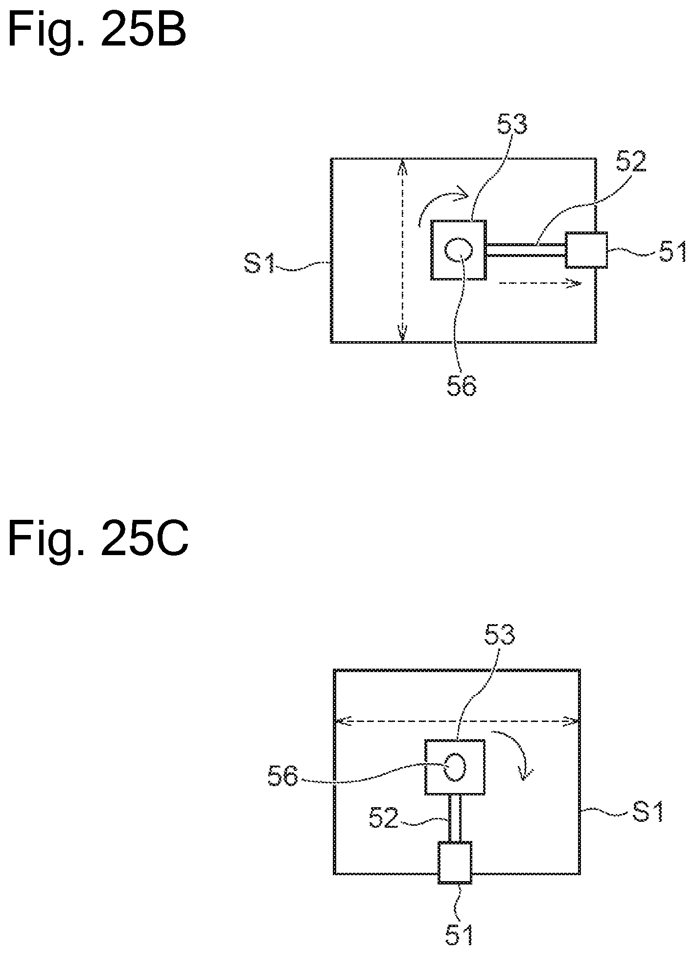
D00021
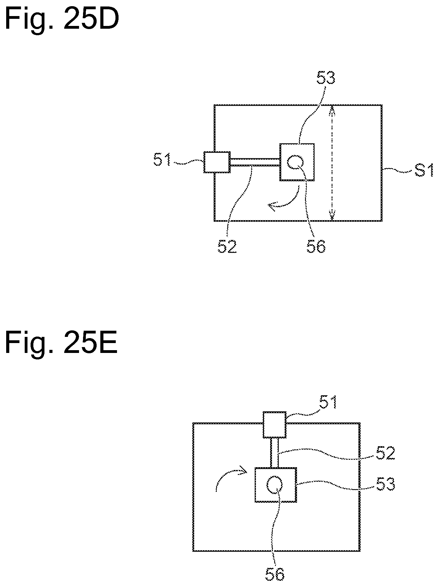
D00022

D00023

D00024

D00025

XML
uspto.report is an independent third-party trademark research tool that is not affiliated, endorsed, or sponsored by the United States Patent and Trademark Office (USPTO) or any other governmental organization. The information provided by uspto.report is based on publicly available data at the time of writing and is intended for informational purposes only.
While we strive to provide accurate and up-to-date information, we do not guarantee the accuracy, completeness, reliability, or suitability of the information displayed on this site. The use of this site is at your own risk. Any reliance you place on such information is therefore strictly at your own risk.
All official trademark data, including owner information, should be verified by visiting the official USPTO website at www.uspto.gov. This site is not intended to replace professional legal advice and should not be used as a substitute for consulting with a legal professional who is knowledgeable about trademark law.