Co Anode, And Co Electroplating Method Using Co Anode
Murata; Shuhei ; et al.
U.S. patent application number 17/041229 was filed with the patent office on 2021-01-14 for co anode, and co electroplating method using co anode. The applicant listed for this patent is JX Nippon Mining & Metals Corporation. Invention is credited to Takayuki Asano, Kengo Kaminaga, Yoshimasa Koido, Shuhei Murata.
| Application Number | 20210010149 17/041229 |
| Document ID | / |
| Family ID | 1000005164833 |
| Filed Date | 2021-01-14 |


| United States Patent Application | 20210010149 |
| Kind Code | A1 |
| Murata; Shuhei ; et al. | January 14, 2021 |
Co Anode, And Co Electroplating Method Using Co Anode
Abstract
Provided is a novel anode for electroplating, which replaces the Cu anode and which is capable of suppressing plating defects. The Co anode has a number of particles with a grain size of 0.5 .mu.m or more of 6000 particles/g or less, as measured by an in-liquid particle counter according to JIS B 9925 after dissolving the Co anode in dilute nitric acid having a nitric acid concentration of 20% by mass.
| Inventors: | Murata; Shuhei; (Ibaraki, JP) ; Koido; Yoshimasa; (Ibaraki, JP) ; Asano; Takayuki; (Ibaraki, JP) ; Kaminaga; Kengo; (Ibaraki, JP) | ||||||||||
| Applicant: |
|
||||||||||
|---|---|---|---|---|---|---|---|---|---|---|---|
| Family ID: | 1000005164833 | ||||||||||
| Appl. No.: | 17/041229 | ||||||||||
| Filed: | October 3, 2018 | ||||||||||
| PCT Filed: | October 3, 2018 | ||||||||||
| PCT NO: | PCT/JP2018/037118 | ||||||||||
| 371 Date: | September 24, 2020 |
| Current U.S. Class: | 1/1 |
| Current CPC Class: | C25D 3/12 20130101; C25D 17/12 20130101 |
| International Class: | C25D 17/12 20060101 C25D017/12; C25D 3/12 20060101 C25D003/12 |
Foreign Application Data
| Date | Code | Application Number |
|---|---|---|
| Mar 28, 2018 | JP | 2018-063008 |
Claims
1. A Co anode for electroplating, the Co anode having a number of particles with a grain size of 0.5 .mu.m or more of 6000 particles/g or less, as measured by an in-liquid particle counter according to JIS B 9925 after dissolving the Co anode in dilute nitric acid having a nitric acid concentration of 20% by mass.
2. The Co anode according to claim 1, wherein the number of particles with a grain size of 0.5 .mu.m or more is 5000 particles/g or less.
3. The Co anode according to claim 1, wherein the Co anode has a purity of 3N or more.
4. The Co anode according to claim 3, wherein the purity is 4N or more.
5. The Co anode according to claim 3, wherein the Co anode has a Fe concentration of 10 ppm or less.
6. The Co anode according to claim 5, wherein the Fe concentration is 5 ppm or less.
7. A Co electroplating method using the Co anode according to claim 1.
8. An evaluation method of Co anode for electroplating, the method comprising the steps of: dissolving the Co anode in dilute nitric acid having a nitric acid concentration of 20% by mass, measuring an in-liquid particle in the dilute nitric acid in which the Co anode is dissolved by an in-liquid particle counter according to JIS B 9925, and judging good or bad of the Co anode based on the measurement result by the in-liquid particle counter.
9. The evaluation method of Co anode for electroplating according to claim 8, wherein the step of judging good or bad of the Co anode based on the measurement result by the in-liquid particle counter includes: a step of evaluating if a number of particles with a grain size greater than or equal to a predetermined grain size of 0.5 .mu.m or more is below a predetermined threshold of 6000 particles/g or less.
Description
FIELD OF THE INVENTION
[0001] The present invention relates to a Co anode and a Co electroplating method using the Co anode.
BACKGROUND OF THE INVENTION
[0002] In general, Cu electroplating is used for forming Cu wiring in PWBs (printed wiring boards) and the like. Recently, it is also used for forming Cu wiring of semiconductors. A pure Cu anode or a phosphorus-containing Cu anode is used as an anode for Cu electroplating for forming the Cu wiring.
[0003] The pure Cu anode or the phosphorus-containing Cu anode used for the Cu electroplating is described in, for example, Patent Literature 1, which discloses that purity is controlled within a predetermined range and an impurity content is controlled below a predetermined value, so that adhesion of particles to a semiconductor wafer manufactured using the pure Cu anode or the phosphorus-containing Cu anode can be suppressed.
[0004] Further, as a similar art for suppressing the adhesion of particles to the semiconductor wafer manufactured using the phosphorus-containing Cu anode, Patent Literature 2 discloses that when subjecting the semiconductor wafer to the Cu electroplating, a fine crystal layer having a crystal grain size controlled within a predetermined range is previously formed on a surface of the phosphorus-containing Cu anode.
CITATION LIST
Patent Literatures
[0005] [Patent Literature 1] Japanese Patent No. 5066577 B [0006] [Patent Literature 2] Japanese Patent No. 4076751 B
SUMMARY OF THE INVENTION
[0007] In recent years, semiconductor devices have been required to have higher performance and lower power consumption, and as wiring becomes finer, measures against electromigration (EM) deterioration which would affect the reliability of wiring and decreasing wiring resistance which would cause signal delay have been required. The arts described in Patent Literature 1 and Patent Literature 2 are to suppress the particles generated when forming Cu wiring or the like by the Cu electroplating as described above, thereby improving plating defects to provide Cu wiring useful for finer wiring. However, there is room for improvement of the electroplating using such a conventional Cu anode, in terms of EM resistance and decreased wiring resistance. Therefore, there would be a need for development of a novel electroplating anode which replaces the Cu anode, and which is capable of suppressing the conventional problem of plating defects.
[0008] Therefore, an object of an embodiment of the present invention is to provide a novel anode for electroplating, which replaces the Cu anode and which is capable of suppressing plating defects.
[0009] As a result of various studies to solve such problems, the present inventors have focused on the fact that, in a technical field of forming fine wiring, replacement of Cu wiring to Co wiring has been attempted in advanced local wiring having narrow wiring and a relatively short wiring distance. The present inventors have found that the Co wiring has better EM resistance than that of the Cu wiring and can achieve wiring resistance which is lower than that of the Cu wiring by a thinner barrier metal layer, when the wiring distance is shorter.
[0010] Therefore, the present inventors have found that an anode for electroplating, which is capable of suppressing plating defects, can be obtained by producing a Co anode in place of the conventional Cu anode and controlling the number of particles having a predetermined grain size or more in the Co anode.
[0011] In an aspect, an embodiment of the present invention completed on the basis of the above findings relates to a Co anode, the Co anode having a number of particles with a grain size of 0.5 .mu.m or more of 6000 particles/g or less, as measured by an in-liquid particle counter according to JIS B 9925 after dissolving the Co anode in dilute nitric acid having a nitric acid concentration of 20% by mass.
[0012] In another aspect, an embodiment of the present invention relates to a Co electroplating method using the Co anode according to the embodiment of the present invention.
[0013] According to an embodiment of the present invention, it is possible to provide a novel anode for electroplating, which replaces the Cu anode and which is capable of suppressing plating defects.
BRIEF DESCRIPTION OF THE DRAWINGS
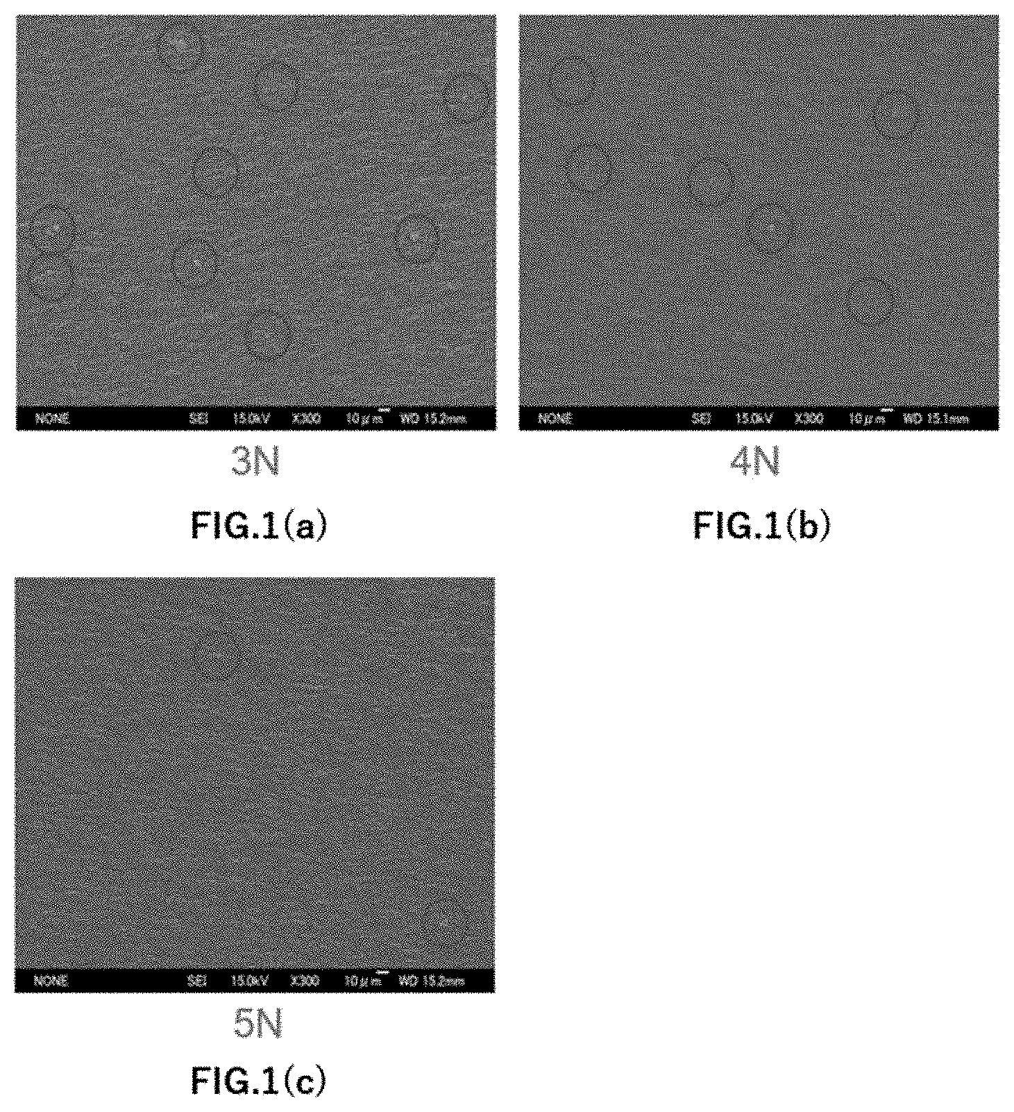
[0014] FIG. 1(a) shows SEM images of Example 5 (purity: 3N, magnification: 300 times); FIG. 1(b) shows images of Example 3 (purity: 4N, magnification: 300 times); and FIG. 1(c) shows images of Example 1 (purity: 5N, magnification: 300 times);
[0015] FIG. 2(a) shows SEM images of Example 5 (purity: 3N, magnification: 15000 times); FIG. 2(b) shows SEM images of Example 3 (purity: 4N, magnification: 30000 times); and FIG. 2(c) shows SEM images of Example 1 (purity: 5N, magnification: 15000 times);
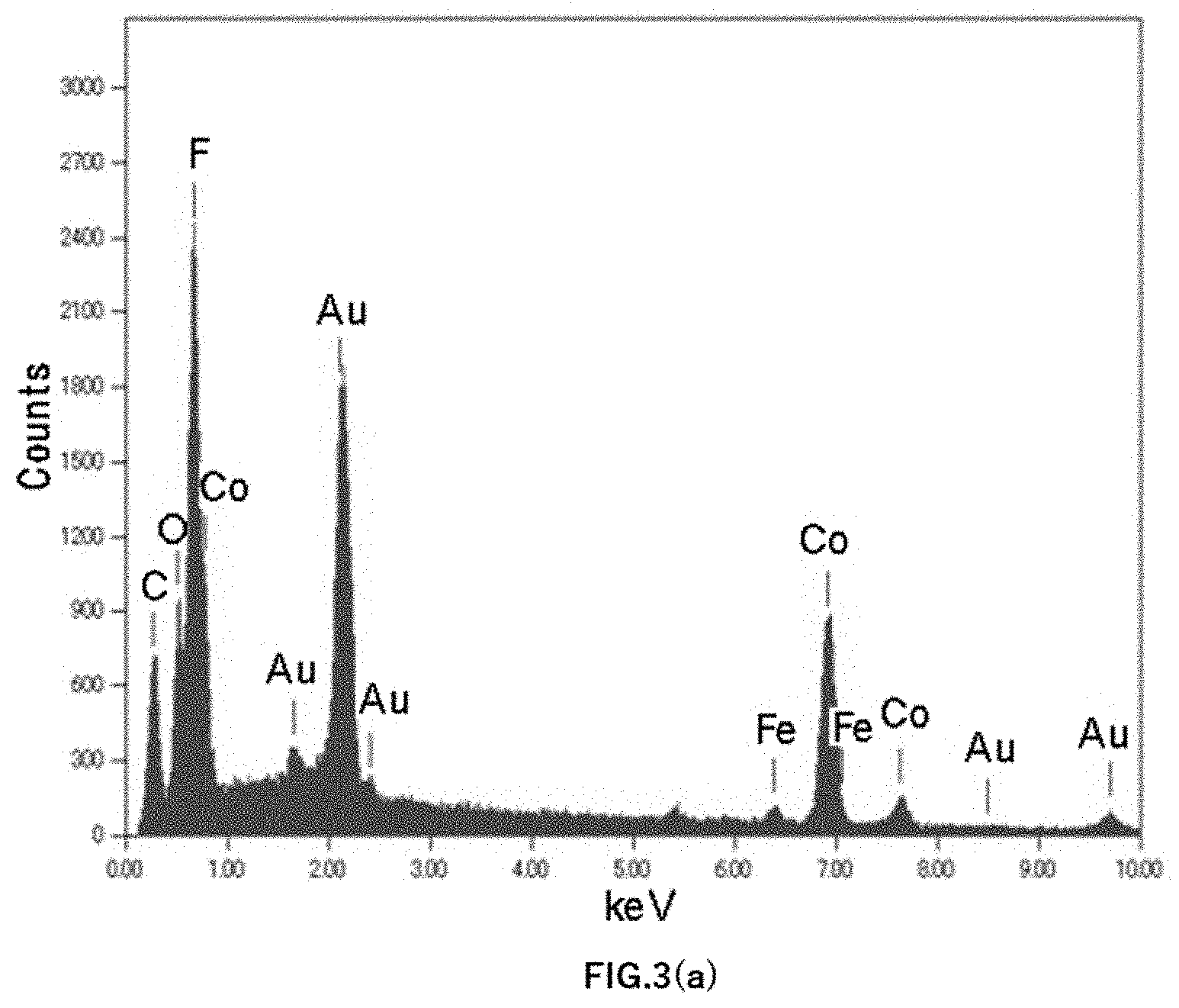
[0016] FIG. 3(a) shows a graph of an EDX spectrum of Example 5;
[0017] FIG. 3(b) shows a graph of an EDX spectrum of Example 3; and
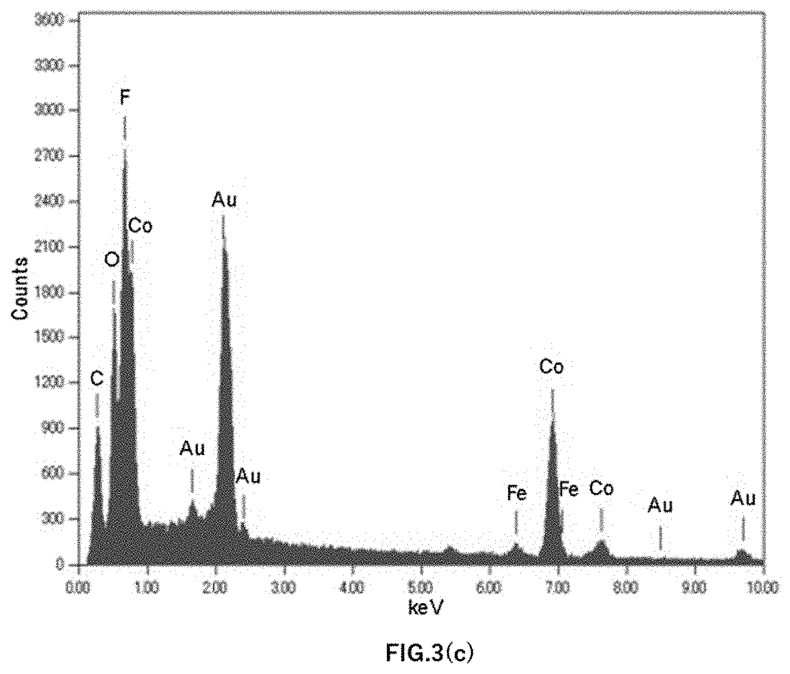
[0018] FIG. 3(c) is a graph of an EDX spectrum of Example 1.
DETAILED DESCRIPTION OF THE INVENTION
[Structure of Co Anode]
[0019] A Co anode according to an embodiment of the present invention has a number of particles with a grain size of 0.5 .mu.m or more of 6000 particles/g or less, as measured by an in-liquid particle counter according to JIS B 9925 after dissolving the Co anode in dilute nitric acid having a nitric acid concentration of 20% by mass. The Co anode has better EM resistance than that of the Cu anode, and can achieve wiring resistance which is lower than that of the Cu wiring by a thinner barrier metal layer, when a wiring distance is shorter. Further, since the number of particles with a grain size of 0.5 .mu.m or more is controlled to 6000 particles/g or less, any occurrence of abnormal deposition of plating can be suppressed when electroplating is performed using the Co anode, thereby resulting in good suppression of plating defects.
[0020] The particles are solid inclusions present in the structure of the Co anode, and refer to those which are not dissolved in dilute nitric acid in the implementation of an in-liquid particle counter as described later. Impurities in the Co anode also include substances that are dissolved in dilute nitric acid (for example, metals having strong ionization tendency). However, even if such substances are present as coarse structures in the Co anode, they are ionized in a process of electroplating, and thus are incorporated into a plated film in a very finer form at an ion level. On the other hand, the inclusions (particles) that are not dissolved in dilute nitric acid are electrochemically stable, and thus are incorporated into the plated film while maintaining the forms close to those present in the Co anode. Therefore, even if Co anodes have the same purity, a Co anode having higher proportion of the particles among the impurities results in a larger size of impurities incorporated into the plated film, so that the plating defects tend to occur. The present invention focuses on this point, and provides the Co anode in which the number of particles having the predetermined grain size or more is controlled, among the particles being solid inclusions that are not dissolved in dilute nitric acid.
[0021] The particles mainly originate from impurities contained in a Co raw material, or impurities or products contaminated in a production step. The particles are, for example, one or more selected from the group consisting of metals, metal oxides, carbon, carbon compounds, and chlorine compounds. Further, the particles may be one or more metals selected from the group consisting of Fe, Mg, Cr, Ni, Si, and Al, or oxides thereof (including cobalt oxide).
[0022] Furthermore, the present inventors have focused on density of the number of particles having a grain size of 0.5 .mu.m or more because the particles having such a grain size are not dissolved in an electrolytic solution and are likely to cause abnormal deposition of plating by being incorporated into the plated film, and found that by controlling the density of the number to 6000 particles/g or less, the generation of the particles in the plated film produced by electroplating can be suppressed very well, resulting in suppression of the generation of abnormal deposition of plating. The present inventors have also found that when comparing a case where the impurities are not detected as the particles with a case where the impurities are detected, the detected particles have an adverse effect on the plating step, and in particular, a Co wiring formed using the Co anode is often utilized as finer wiring, which will make such an adverse effect remarkable. From this viewpoint, the present invention controls the number of particles having the grain size of 0.5 .mu.m or more. In the Co anode according to the embodiment of the present invention, the number of particles having the grain size of 0.5 .mu.m or more is preferably 5000 particles/g or less, and more preferably 4000 particles/g or less.
[0023] The grain size of the particles is determined by measurement with a "light scattering type automatic particle counter for liquid" (from Kyushu Rion Co., Ltd.). This measuring method is to select the sizes of particles in a liquid and measure the particle concentration and the number of particles, and is based on JIS B 9925 (as used herein, the measurement is referred to as "in-liquid particle counter").
[0024] The procedure for carrying out the in-liquid particle counter will be specifically described. One gram of a sample was taken and slowly dissolved in 150 ml of dilute nitric acid (an aqueous solution of 20% by mass nitric acid) so as not to dissolve the particles, and left for 24 hours and then diluted with pure water to 500 ml, 10 ml of which is taken and measured with the in-liquid particle counter. For example, when the number of particles is 1000 particles/ml, 0.02 g of the sample will be measured in 10 ml of the solution, so that the number of particles will be 500000 particles/g.
[0025] It should be noted that the measurement of the number of particles is not limited to the measurement with the in-liquid particle counter, and other means may be used as long as the number of the particles can be measured in the same manner.
[0026] The Co anode according to an embodiment of the present invention preferably has a purity of 3N or more. The purity of the Co anode of 3N (a purity of 99.9% by mass) or more can more effectively suppress the generation of the particles in the plated film produced by electroplating using the Co anode, resulting in better suppression of the generation of abnormal deposition. The Co anode according to the embodiment of the present invention preferably has a purity of 4N (purity of 99.99% by mass) or more, and more preferably 5N (purity of 99.999% by mass) or more. With regard to the "higher purity" as used herein, for example, a purity of 5N (99.999%) means that the total amount of all metal elements other than elements below lower detection limit and Co, such as Be, Na, Mg, Al, Si, P, S, K, Ca, Ti, V, Cr, Mn, Fe, Ni, Cu, Zn, As, Zr, Mo, Cd, Sn, Sb, Hg, Pb, Bi, Th, and U are less than 10 ppm, when analyzing a dissolved Co ingot by glow discharge mass spectrometry (GDMS: Glow Discharge Mass Spectrometry).
[0027] It should be noted that, as shown in Examples and Comparative Example as described later, the "higher purity" does not necessarily mean that the number of particles is lower, and the Co anode having higher purity may exhibit a larger number of particles in the present invention than the Co anode having lower purity.
[0028] The Co anode according to an embodiment of the present invention preferably has a Fe concentration controlled to 10 ppm or less. Since Fe is difficult to be dissolved in an acidic solution, the contamination of Fe in the Co anode tends to easily form the particles. When comparing Co anodes having the same purity, the Co anode having the Fe concentration controlled to 10 ppm or less produces fewer particles in the plated film than the Co anode having the Fe concentration of more than 10 ppm, resulting in further suppression of the generation of abnormal deposition of plating. In the Co anode according to the embodiment of the present invention, the Fe concentration is controlled to more preferably 8 ppm or less, and even more preferably 5 ppm or less, and still more preferably 3 ppm or less, and still more preferably 1 ppm or less, and still more preferably 0 ppm.
[Method for Producing Co Anode]
[0029] A method for producing the Co anode according to the embodiment of the present invention will be described in detail. First, Co, a raw material, is melted in a certain container. Examples of the Co raw material to be used include Co having a purity of 3N (a purity of 99.9% by mass) or more.
[0030] As described above, the particles that are problematic during electroplating are grains of compounds of Fe, Mg, Cr, Ni, Si, Al and the like, and these grains cause the particles generated in the plated film. In order to prevent these particles from mixing into the Co anode, a surface roughness of a portion in contact with the Co material in the container, piping and mold may be controlled. Further, based on the findings that these particles tend to float on a slag side, a stirring time of a molten metal may be increased to distribute the particles of compounds of Fe, Mg, Cr, Ni, Si, and Al each having a grain size of more than 0.5 .mu.m to the slag side.
[0031] The melted Co raw material is then fed to a mold and forged, and then subjected to rolling, a heat treatment, and further surface cutting to produce a Co anode.
[Co Electroplating Method]
[0032] Co electroplating using the Co anode according to the embodiment of the present invention can lead to very good suppression of the generation of the particles in a plated film to be produced, resulting in suppression of the generation of abnormal deposition of plating.
[0033] In the Co electroplating method according to an embodiment of the present invention, for example, an appropriate amount of cobalt sulfate: 10 to 30 g/L (Co) or cobalt chloride 5 to 15 g/L may be used as a plating bath, although not particularly limited thereto. A pH is from 2.5 to 3.5.
[0034] In addition, a plating bath temperature can be from 25 to 60.degree. C., a cathode current density can be from 0.5 to 10 A/dm.sup.2, and an anode current density can be from 0.5 to 10 A/dm.sup.2, although those conditions are not necessarily limited to thereto. The plating bath may contain a brightening agent/complexing agent, a pH buffering agent, a surfactant and the like.
EXAMPLES
[0035] Examples are provided below for better understanding of the present invention and its advantages, but the present invention is not limited to these Examples.
[Preparation of Co Anode]
[0036] For each of Examples 1 to 5 and Comparative Example 1, a Co raw material having the predetermined purity was melted under vacuum to prepare an ingot, which was then melted. The Co raw material having purity of 3N was a commercially available cobalt material, and the Co raw materials having purity of 4N and 5N were obtained by electrolytic refining.
[0037] The melted Co raw material was then fed to the mold and forged, and subjected to rolling at a rolling reduction rate of from 30 to 50%, followed by a heat treatment at 300.degree. C. to 600.degree. C. and further surface cutting, to produce a Co anode.
[Evaluation]
(Evaluation of Particles)
[0038] The particle size and number of the particles were measured with a "light scattering type automatic particle counter for liquid" (from Kyushu Rion Co., Ltd.). Specifically, 1 g of a Co anode was sampled and slowly dissolved in 150 ml of dilute nitric acid (an aqueous solution of 20% by mass nitric acid) so as not to dissolve the particles, and left for 24 hours, and further diluted with pure water to 500 ml, 10 ml of which was taken and measured with the in-liquid particle counter. An average value obtained by repeating this procedure three times was determined to be the number of particles. The particle size of the particles was evaluated by a SEM image. FIG. 1(a) shows a SEM image of Example 5 (purity: 3N, magnification: 300 times), FIG. 1(b) shows a SEM image of Example 3 (purity: 4N, magnification: 300 times), and FIG. 1(c) shows a SEM image of Example 1 (purity: 5N, magnification: 300 times. Further, FIG. 2(a) shows a SEM image of Example 5 (purity: 3N, magnification: 15000 times), FIG. 2(b) shows a SEM image of Example 3 (purity: 4N, magnification: 30000 times), and FIG. 2(c) shows a SEM image of Example 1 (purity: 5N, magnification: 15000 times). Furthermore, in FIG. 1, the particles (inclusions) having a grain size of 0.5 .mu.m or more are shown by surrounding them by frame lines.
(Evaluation of Fe Concentration)
[0039] The concentration of Fe contained in the Co anode was evaluated by GDMS. Further, the particle components remaining on a filter when measuring the particle size and number of particles were evaluated using energy dispersive X-ray analysis (EDX: Energy Dispersive X-ray Spectrometry). FIG. 3(a) shows an EDX spectrum graph of Example 5, FIG. 3(b) shows an EDX spectrum graph of Example 3, and FIG. 3(c) shows an EXD spectrum graph of Example 1.
(Evaluation of Number of Abnormal Electrodepositions)
[0040] On a wafer having a diameter of 300 mm, Co electroplating was performed under the same conditions using each of the Co anodes of Examples 1 to 5 and Comparative Example 1 to form a Co plated film having a thickness of 10 nm. The number of defects (the number of abnormal electrodepositions) generated in the Co plated film was evaluated.
[0041] Table 1 shows the results of the above Examples and Comparative example.
TABLE-US-00001 TABLE 1 Comparative Example 1 Example 2 Example 3 Example 4 Example 5 Example 1 Purity 5N 5N 4N 4N 3N 3N Fe Concentration (ppm) 0.8 7 1.2 6 4.1 12 Particles Having Grain Size 1200 2900 3700 5900 4800 9700 of 0.5 .mu.m or more (particles/g) Number of Abnormal 0 0 0 0 0 1 Electrodepositions per a Wafer in Co Plating Having Thickness of 10 nm
(Evaluation Results)
[0042] Each of Examples 1 to 5 could produce a Co anode in which the number of particles having a grain size of 0.5 .mu.m or more was 6000 particles/g or less. However, Comparative Example 1 produced a Co anode in which the number of particles having a grain size of 0.5 .mu.m or more was more than 6000 particles/g.
[0043] Further, Example 1 and Example 2, Example 3 and Example 4, and Example 5 and Comparative Example 1 used Co anodes having the same purity, respectively, but they had different Fe concentrations, resulting in a difference in the number of particles having a grain diameter of 0.5 .mu.m or more. It is understood from this result that if the Co anodes have the same purity, a Co anode having a lower Fe concentration can decrease a larger number of particles having a grain size of 0.5 .mu.m or more.
[0044] In addition, Example 4 where the purity was 4N had a larger number of particles having a grain size of 0.5 .mu.m or more than that of Example 5 where the purity was 3N. Thus, the "higher purity" does not necessarily lead to the lower number of particles, and the Co anode having higher purity may have the larger number of particles according to the present invention than that of the Co anode having lower purity.
[0045] Further, in the Co plated film formed using each of the Co anodes of Examples 1 to 5, the number of abnormal electrodepositions was zero, and the plating defects were well suppressed. In the Co plated film formed using the Co anode of Comparative Example 1, the abnormal electrodeposition was confirmed and plating defects were generated.
* * * * *
D00000
D00001
D00002
D00003
D00004
D00005
XML
uspto.report is an independent third-party trademark research tool that is not affiliated, endorsed, or sponsored by the United States Patent and Trademark Office (USPTO) or any other governmental organization. The information provided by uspto.report is based on publicly available data at the time of writing and is intended for informational purposes only.
While we strive to provide accurate and up-to-date information, we do not guarantee the accuracy, completeness, reliability, or suitability of the information displayed on this site. The use of this site is at your own risk. Any reliance you place on such information is therefore strictly at your own risk.
All official trademark data, including owner information, should be verified by visiting the official USPTO website at www.uspto.gov. This site is not intended to replace professional legal advice and should not be used as a substitute for consulting with a legal professional who is knowledgeable about trademark law.