Method For Depositing Silicon-free Carbon-containing Film As Gap-fill Layer By Pulse Plasma-assisted Deposition
Blanquart; Timothee Julien Vincent
U.S. patent application number 16/988374 was filed with the patent office on 2020-11-26 for method for depositing silicon-free carbon-containing film as gap-fill layer by pulse plasma-assisted deposition. The applicant listed for this patent is ASM IP Holding B.V.. Invention is credited to Timothee Julien Vincent Blanquart.
| Application Number | 20200373152 16/988374 |
| Document ID | / |
| Family ID | 1000005004958 |
| Filed Date | 2020-11-26 |


View All Diagrams
| United States Patent Application | 20200373152 |
| Kind Code | A1 |
| Blanquart; Timothee Julien Vincent | November 26, 2020 |
METHOD FOR DEPOSITING SILICON-FREE CARBON-CONTAINING FILM AS GAP-FILL LAYER BY PULSE PLASMA-ASSISTED DEPOSITION
Abstract
A Si-free C-containing film having filling capability is deposited by forming a viscous polymer in a gas phase by striking an Ar, He, or N.sub.2 plasma in a chamber filled with a volatile hydrocarbon precursor that can be polymerized within certain parameter ranges which define mainly partial pressure of precursor during a plasma strike, and wafer temperature.
| Inventors: | Blanquart; Timothee Julien Vincent; (Tokyo, JP) | ||||||||||
| Applicant: |
|
||||||||||
|---|---|---|---|---|---|---|---|---|---|---|---|
| Family ID: | 1000005004958 | ||||||||||
| Appl. No.: | 16/988374 | ||||||||||
| Filed: | August 7, 2020 |
Related U.S. Patent Documents
| Application Number | Filing Date | Patent Number | ||
|---|---|---|---|---|
| 16455406 | Jun 27, 2019 | 10755923 | ||
| 16988374 | ||||
| 16026711 | Jul 3, 2018 | 10388513 | ||
| 16455406 | ||||
| Current U.S. Class: | 1/1 |
| Current CPC Class: | H01L 21/76224 20130101; H01L 21/76229 20130101; H01L 21/02115 20130101; H01L 21/0228 20130101; C23C 16/26 20130101; C23C 16/45542 20130101; C23C 16/50 20130101; H01L 21/02274 20130101; H01L 21/0234 20130101; H01L 21/02205 20130101 |
| International Class: | H01L 21/02 20060101 H01L021/02; C23C 16/26 20060101 C23C016/26; C23C 16/50 20060101 C23C016/50; C23C 16/455 20060101 C23C016/455; H01L 21/762 20060101 H01L021/762 |
Claims
1. A method of filling a patterned recess on a surface of a substrate, the method comprising the steps of: providing a substrate comprising a recess in a reaction space; providing a silicon-free carbon-containing precursor to the reaction space, thereby filling the recesses with a gas phase precursor; and providing a plasma to the reaction space, thereby forming a viscous material in the recess, wherein the viscous material flows in the recess and accumulates at a bottom of the recess to thereby form deposited material at the bottom of the recess, and wherein the deposited material solidifies.
2. The method according to claim 1, wherein the precursor is provided with a precursor flow as a portion of a total gas flow to the reaction space in a range of about 10% to about 100%.
3. The method according to claim 1, wherein a partial pressure of the precursor in the reaction space is greater than 200 Pa.
4. The method according to claim 1, wherein a temperature of the substrate is between about 50.degree. C. to about 150.degree. C.
5. The method according to claim 1, wherein a total pressure within the reaction space is greater than 500 Pa.
6. The method according to claim 1, wherein the precursor is polymerized using the plasma.
7. The method according to claim 6, wherein an average chain length of the viscous material is greater than ten times an average chain length of a molecule of the precursor.
8. The method according to claim 1, wherein an amount of material deposited on the bottom is greater than an amount of material deposited on a sidewall of the recess.
9. The method according to claim 1, wherein the precursor comprises an unsaturated hydrocarbon.
10. The method according to claim 9, wherein the precursor comprises one or more of unsaturated or cyclic hydrocarbon having a vapor pressure of 1,0000 Pa or more at 25.degree. C.
11. The method according to claim 1, wherein the precursor comprises one or more compounds selected from the group consisting of C2-C8 alkynes (C.sub.nH.sub.2n-2), C2-C8 alkenes (C.sub.nH.sub.2n), C2-C8 diene (C.sub.nH.sub.n+2), C3-C8 cycloalkenes, C3-C8 annulenes (C.sub.nH.sub.n), C3-C8 cycloalkanes, and substituted hydrocarbons of the foregoing.
12. The method according to claim 1, wherein the precursor comprises cyclopentene.
13. The method according to claim 1, wherein the recess has a width and a depth with an aspect ratio of about 2 to about 10.
14. The method according to claim 1, wherein the viscous material is liquid.
Description
CROSS-REFERENCE TO RELATED APPLICATIONS
[0001] This application is a continuation of U.S. patent application Ser. No. 16/455,406, filed Jun. 27, 2019, which is a continuation of U.S. patent application Ser. No. 16/026,711, filed Jul. 3, 2018, the disclosures of which are herein incorporated by reference in their entireties.
BACKGROUND OF THE INVENTION
Field of the Invention
[0002] The present invention generally relates to a method for depositing a silicon-free carbon-containing film as a gap-fill layer in trenches by pulse plasma-assisted deposition.
Description of the Related Art
[0003] In processes of fabricating integrated circuits such as those for shallow trench isolation, inter-metal dielectric layers, passivation layers, etc., it is often necessary to fill trenches (any recess typically having an aspect ratio of one or higher) with insulating material. However, with miniaturization of wiring pitch of large scale integration (LSI) devices, void-free filling of high aspect ratio spaces (e.g., AR.gtoreq.3) becomes increasingly difficult due to limitations of existing deposition processes.
[0004] FIG. 2 illustrates schematic cross sectional views of trenches subjected to a conventional plasma-enhanced CVD process for gap-filling in the order of (a) and (b). In the conventional plasma-enhanced CVD process, since plasma reaction occurs in a gas phase and reaction products accumulate on a surface of a substrate, film growth is faster at the top of a trench 103 of a substrate 101 than inside the trench 103. As a result, when a layer 102 is deposited, an overhang part 104 is necessarily formed as illustrated in (a). Further, since in the conventional CDV process, deposition is performed layer by layer, when a next layer 105 is deposited on the layer 102, the upper opening of the trench 103 is closed, leaving a void 106 inside the trench 103 as illustrated in (b).
[0005] FIG. 3 illustrates schematic cross sectional views of trenches subjected to a conventional gap-fill process in the order of (a), (b), and (c) using an inhibitor. By depositing an inhibitor 202 in a trench 201, which inhibits reaction products from accumulating on a surface which is covered with the inhibitor, as illustrated in (b), the reaction products do not accumulate on the top surface and at the top of the trench 201, while accumulating at the bottom of the trench 201, achieving bottom-up fill 203 as illustrated in (c). However, it is difficult to find suitable combinations of an inhibitor and an activator, and to find suitable process conditions for deposition. In many cases, it is not practical.
[0006] FIG. 4 illustrates schematic cross sectional views of trenches subjected to a conventional gap-fill process in the order of (a) and (b) using a highly anisotropic process. The high anisotropic process is typically an ion-driven deposition wherein ion bombardment by a plasma containing ions causes plasma reaction for depositing a layer, thereby anisotropically depositing a layer 302 on a top surface and a layer 303 inside a trench 301 as bottom-up fill, as illustrated in (b). However, when the trench is deeper, in order to bombard a bottom area of the trench with ions, the mean free path of ions has to be made longer to reach the bottom area by, e.g., significantly reducing pressure to a hard vacuum, which is often costly and unpractical.
[0007] FIG. 5 illustrates schematic cross sectional views of trenches subjected to a conventional gap-fill process in the order of (a) and (b), or (c) and (d), using a volume expansion treatment ((d) shows loading effect). After depositing a layer 402 on a surface of a substrate 405 having a trench 401 as illustrated in (a), by, e.g., oxidizing the layer, the layer can be expanded, thereby increasing the volume or thickness of the layer and closing the gap (trench) 401 as illustrated in (b). However, as illustrated in (c), when trenches consist of a narrow trench 401 and a wide trench 403, due to the loading effect (i.e., a variation of filling speed depending on the density of a pattern is called the "loading effect"), even when the narrow trench is closed, the wide trench still has a significant opening 404 as illustrated in (d). Also, when the layer is expanded and closes the trench, the layers facing each other push against each other, thereby exerting stress on the sidewalls of the trench as indicated in (d) by arrows, which often causes the structure of the trench to partially or significantly collapse.
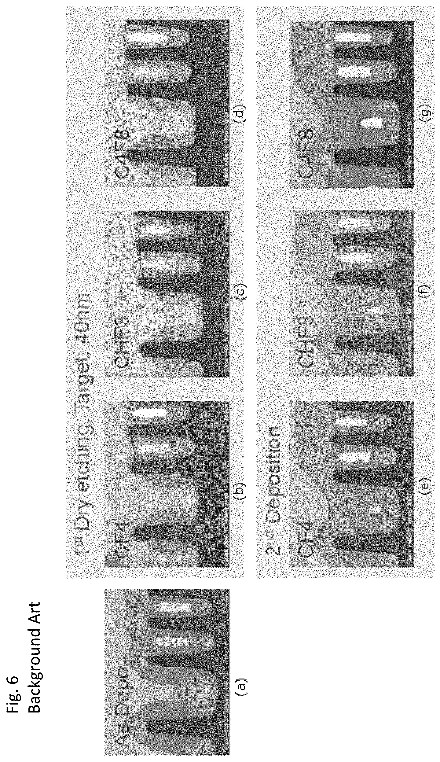
[0008] FIG. 6 shows STEM photographs of cross-sectional views of trenches subjected to a conventional gap-fill process using a combination of deposition in (a), dry-etching in (b) to (d) using different etchants, and second deposition in (e) to (g) corresponding to (b) to (d), respectively. By combining deposition and etching, the topology or geometry of a gap-filled trench can be adjusted. However, as shown in FIG. 6, regardless of the type of etchant (CF.sub.4 in (b) and (e), CHF.sub.3 in (c) and (f), and C.sub.4F.sub.8 in (d) and (g)), the initial voids in the narrow trenches were not filled by etching and subsequent deposition. Further, as shown in FIG. 6, the loading effect manifested. Additionally, this process is time consuming since at least deposition is repeated and therebetween etching is performed.
[0009] FIG. 7 illustrates schematic cross sectional views of trenches subjected to a conventional gap-fill process in the order of (a) and (b) using a flowable material. Since liquid or viscous gas is flowable and naturally moves to the bottom of a trench, by using such liquid or viscous gas, a trench 502 formed in a substrate 501 can be filled with the flowable material, forming bottom-up fill 503 as illustrated in (b). Normally, in order to keep the material flowable, the temperature of the substrate is kept at a low temperature such as 50.degree. C. or lower. This process is very fast and efficient. Although the loading effect is manifested, that is not normally a problem because all the trenches can be overfilled, followed by CMP. However, the material is typically of very poor quality and requires an additional curing step. Further, when the trench is narrow, surface tension of the flowable material interferes with or even blocks entry of the flowable material into the inside of the trench. FIG. 8 illustrates a schematic cross sectional view of trenches subjected to a conventional gap-fill process using a flowable material and shows the above problem. In this process, a flowable state of a precursor is achieved by polymerization in a reaction chamber which occurs when mixing with another precursor in a gas phase above a substrate, i.e., before reaching the surface of the substrate and/or immediately after contacting the top surface of the substrate. By polymerization with the other precursor in the gas phase, the precursor immediately changes to a flowable state before reaching the surface of the substrate and/or at the moment of contacting the top surface of the substrate when its temperature is kept at very low temperature. In any case, the flowable state is achieved always before entering into the trench. As a result, as illustrated in FIG. 8, the flowable material 504 does not enter the trench 502 of the substrate 501, and due to the surface tension of the flowable material 504, the top opening of the trench 502 is clogged by a lump 505, and entry of the flowable material 504 into the trench 502 is blocked. Additionally, in order to form a flowable state of a precursor, the process always uses oxygen and nitrogen, sometimes hydrogen chemistry, and/or the precursor must have very low vapor pressure.
[0010] In view of the conventional gap-fill technology, an embodiment of the present invention provides complete gap-filling by plasma-assisted deposition using a hydrocarbon precursor substantially without formation of voids under conditions where a nitrogen, oxygen, or hydrogen plasma is not required. The embodiment can solve one or more of the above-discussed problems.
[0011] Any discussion of problems and solutions involved in the related art has been included in this disclosure solely for the purposes of providing a context for the present invention, and should not be taken as an admission that any or all of the discussion were known at the time the invention was made.
SUMMARY OF THE INVENTION
[0012] An object of the present invention in some embodiments is to provide a Si-free C-containing film having filling capability. In some embodiments, it can be accomplished by forming a viscous polymer in a gas phase by striking an Ar or He plasma in a chamber filled with a volatile unsaturated or cyclic hydrocarbon precursor that can be polymerized within certain parameter ranges which define mainly partial pressure of precursor during a plasma strike, and wafer temperature. The viscous phase flows at a bottom of a trench and fills the trench with a film having bottom-up seamless capabilities. In some embodiments, this process can be demonstrated preferably using cyclopentene as a precursor; however many other unsaturated or cyclic hydrocarbon compounds can be used singly or in any combination. In some embodiments, preferably, the process uses exclusively a silicon-free hydrocarbon precursor, and an inert gas to strike a plasma. In some embodiments, preferably, the process uses ALD-like recipes (e.g., feed/purge/plasma strike/purge) wherein the purge after feed is voluntarily severely shortened to leave high partial pressure of precursor during the plasma strike. This is clearly distinguished from ALD chemistry or mechanism.
[0013] The above processes can be based on pulse plasma CVD which also imparts good filling capabilities to resultant films although the ALD-like recipes may be more beneficial as discussed later.
[0014] In some embodiments, the critical aspects for flowability of depositing film include: [0015] 1) High enough partial pressure during the entire RF-ON period for polymerization/chain growth to progress;
[0016] 2) Sufficient energy to activate the reaction (defined by the RF-ON period and RF power), a not overly long RF-ON period; and
[0017] 3) Temperature and pressure for polymerization/chain growth set above a melting point of flowable phase but below a boiling point of the deposited material.
[0018] For purposes of summarizing aspects of the invention and the advantages achieved over the related art, certain objects and advantages of the invention are described in this disclosure. Of course, it is to be understood that not necessarily all such objects or advantages may be achieved in accordance with any particular embodiment of the invention. Thus, for example, those skilled in the art will recognize that the invention may be embodied or carried out in a manner that achieves or optimizes one advantage or group of advantages as taught herein without necessarily achieving other objects or advantages as may be taught or suggested herein.
[0019] Further aspects, features and advantages of this invention will become apparent from the detailed description which follows.
BRIEF DESCRIPTION OF THE DRAWINGS
[0020] These and other features of this invention will now be described with reference to the drawings of preferred embodiments which are intended to illustrate and not to limit the invention. The drawings are greatly simplified for illustrative purposes and are not necessarily to scale.
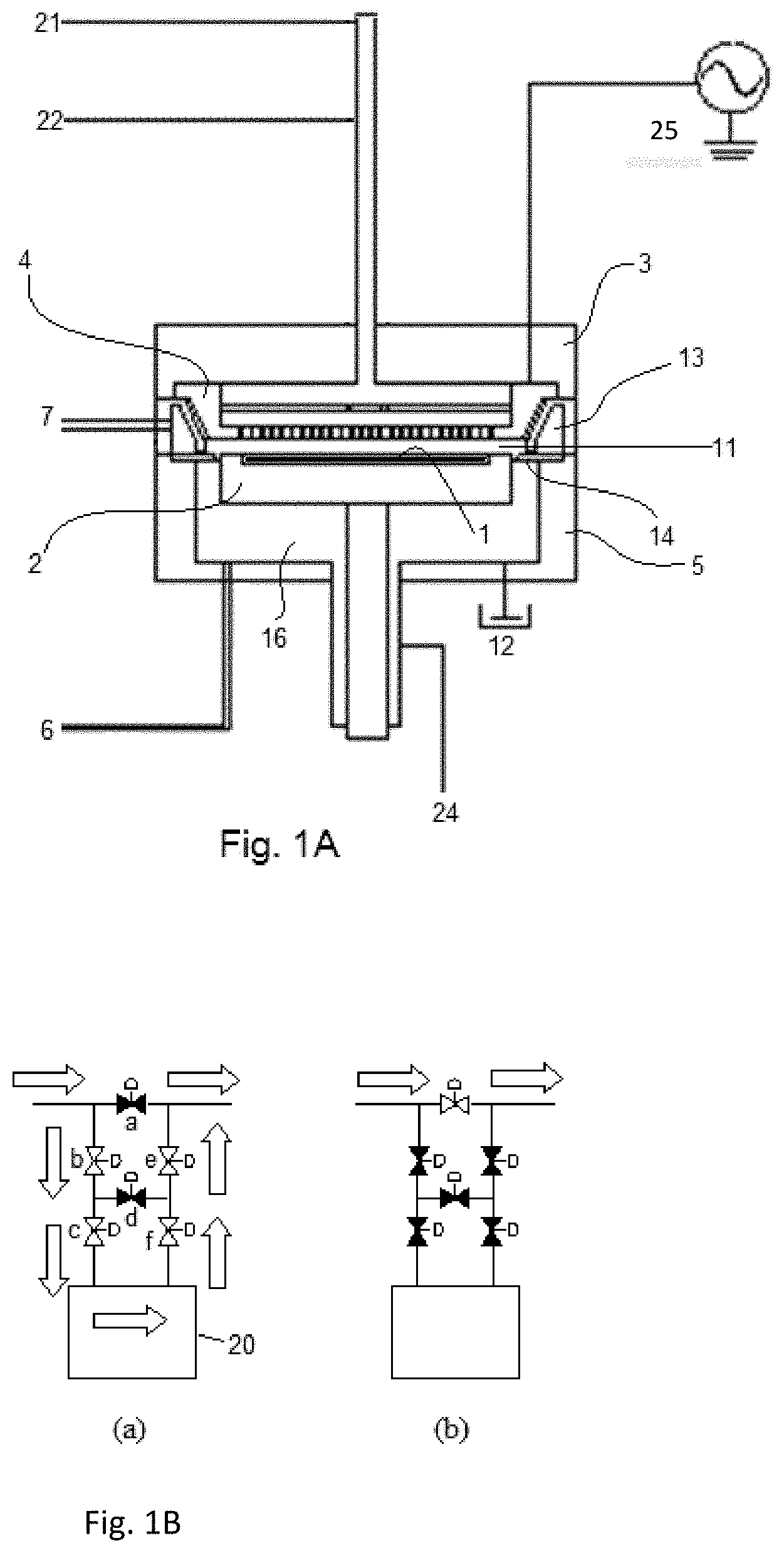
[0021] FIG. 1A is a schematic representation of a PEALD (plasma-enhanced atomic layer deposition) apparatus for depositing a dielectric film usable in an embodiment of the present invention.
[0022] FIG. 1B illustrates a schematic representation of a precursor supply system using a flow-pass system (FPS) usable in an embodiment of the present invention.
[0023] FIG. 2 illustrates schematic cross sectional views of trenches subjected to a conventional CVD process for gap-filling in the order of (a) and (b).
[0024] FIG. 3 illustrates schematic cross sectional views of trenches subjected to a conventional gap-fill process in the order of (a), (b), and (c) using an inhibitor.
[0025] FIG. 4 illustrates schematic cross sectional views of trenches subjected to a conventional gap-fill process in the order of (a) and (b) using a highly anisotropic process.
[0026] FIG. 5 illustrates schematic cross sectional views of trenches subjected to a conventional gap-fill process in the order of (a) and (b), or (c) and (d), using a volume expansion treatment ((d) shows loading effect).
[0027] FIG. 6 shows STEM photographs of cross-sectional views of trenches subjected to a conventional gap-fill process using a combination of deposition in (a), dry-etching in (b) to (d) using different etchants, and second deposition in (e) to (g) corresponding to (b) to (d), respectively.
[0028] FIG. 7 illustrates schematic cross sectional views of trenches subjected to a conventional gap-fill process in the order of (a) and (b) using a flowable material.
[0029] FIG. 8 illustrates a schematic cross sectional view of trenches subjected to a conventional gap-fill process using a flowable material.
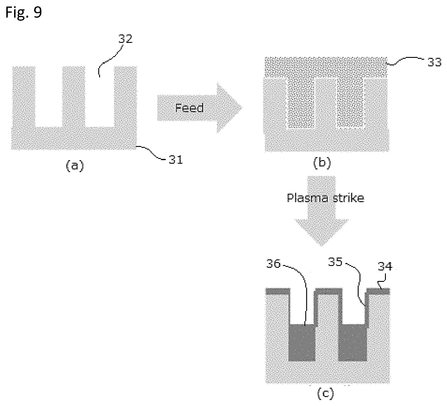
[0030] FIG. 9 illustrates schematic cross sectional views of trenches subjected to a gap-fill process in the order of (a), (b), and (c) according to an embodiment of the present invention.
[0031] FIG. 10 shows STEM photographs of cross-sectional views of deep trenches subjected to gap-fill cycles repeated 240 times in (a), and trenches having different opening sizes (widths) subjected to gap-fill cycles repeated 240 times in (b) according to an embodiment of the present invention.
[0032] FIG. 11 shows STEM photographs of cross-sectional views of wide trenches subjected to gap-fill cycles in (a), wide and narrow trenches subjected to gap-fill cycles in (b), and narrow trenches subjected to gap-fill cycles in (c) according to a comparative example.
[0033] FIG. 12 shows graphs indicating the schematic relationship between process parameters and flowability obtained using data analysis software JMP.RTM. according to an embodiment of the present invention.
[0034] FIGS. 13 to 28 show STEM photographs of cross-sectional views of trenches subjected to gap-fill deposition by PEALD-like recipes, wherein FIG. 27 shows a B/T ratio of 3.0 or higher, FIG. 28 shows a B/T ratio of 2.5 or higher but less than 3.0, FIGS. 13 and 24 show a B/T ratio of 2.0 or higher but less than 2.5, FIGS. 14, 15, 16, and 25 show a B/T ratio of 1.5 or higher but less than 2.0, and FIGS. 17 to 23 and 26 show a B/T ratio of less than 1.5 (comparative examples).
DETAILED DESCRIPTION OF EMBODIMENTS
[0035] In this disclosure, "gas" may include vaporized solid and/or liquid and may be constituted by a single gas or a mixture of gases, depending on the context. Likewise, an article "a" or "an" refers to a species or a genus including multiple species, depending on the context. In this disclosure, a process gas introduced to a reaction chamber through a showerhead may be comprised of, consist essentially of, or consist of a silicon-free hydrocarbon precursor and an additive gas. The additive gas may include a plasma-generating gas for exciting the precursor to deposit amorphous carbon when RF power is applied to the additive gas. The additive gas may be an inert gas which may be fed to a reaction chamber as a carrier gas and/or a dilution gas. The additive gas may contain no reactant gas for oxidizing or nitriding the precursor. Alternatively, the additive gas may contain a reactant gas for oxidizing or nitriding the precursor to the extent not interfering with plasma polymerization forming an amorphous carbon-based polymer. Further, in some embodiments, the additive gas contains only noble gas. The precursor and the additive gas can be introduced as a mixed gas or separately to a reaction space. The precursor can be introduced with a carrier gas such as a rare gas. A gas other than the process gas, i.e., a gas introduced without passing through the showerhead, may be used for, e.g., sealing the reaction space, which includes a seal gas such as a rare gas. In some embodiments, the term "precursor" refers generally to a compound that participates in the chemical reaction that produces another compound, and particularly to a compound that constitutes a film matrix or a main skeleton of a film, whereas the term "reactant" refers to a compound, other than precursors, that activates a precursor, modifies a precursor, or catalyzes a reaction of a precursor, wherein the reactant may provide an element (such as N, C) to a film matrix and become a part of the film matrix, when RF power is applied. The term "inert gas" refers to a plasma-generating gas that excites a precursor when RF power is applied, but unlike a reactant, it does not become a part of a film matrix.
[0036] In some embodiments, "film" refers to a layer continuously extending in a direction perpendicular to a thickness direction substantially without pinholes to cover an entire target or concerned surface, or simply a layer covering a target or concerned surface. In some embodiments, "layer" refers to a structure having a certain thickness formed on a surface or a synonym of film or a non-film structure. A film or layer may be constituted by a discrete single film or layer having certain characteristics or multiple films or layers, and a boundary between adjacent films or layers may or may not be clear and may be established based on physical, chemical, and/or any other characteristics, formation processes or sequence, and/or functions or purposes of the adjacent films or layers. Further, in this disclosure, any two numbers of a variable can constitute a workable range of the variable as the workable range can be determined based on routine work, and any ranges indicated may include or exclude the endpoints. Additionally, any values of variables indicated (regardless of whether they are indicated with "about" or not) may refer to precise values or approximate values and include equivalents, and may refer to average, median, representative, majority, etc. in some embodiments. Further, in this disclosure, the terms "constituted by" and "having" refer independently to "typically or broadly comprising," "comprising," "consisting essentially of," or "consisting of" in some embodiments. In this disclosure, any defined meanings do not necessarily exclude ordinary and customary meanings in some embodiments.
[0037] In this disclosure, "continuously" refers to without breaking a vacuum, without interruption as a timeline, without any material intervening step, without changing treatment conditions, immediately thereafter, as a next step, or without an intervening discrete physical or chemical structure between two structures other than the two structures in some embodiments.
[0038] In this disclosure, the term "filling capability" refers to a capability of filling a gap substantially without voids (e.g., no void having a size of approximately 5 nm or greater in diameter) and seams (e.g., no seam having a length of approximately 5 nm or greater), wherein seamless/voidless bottom-up growth of a layer is observed, which growth at a bottom of a gap is at least approximately 1.5 times faster than growth on sidewalls of the gap and on a top surface having the gap. A film having filling capability is referred to also as "flowable film" or "viscous film." The flowable or viscous behavior of film is often manifested as a concave surface at a bottom of a trench. For example, FIG. 13 shows STEM photographs of cross-sectional views of trenches having different opening sizes (widths) subjected to gap-fill cycles according to an embodiment of the present invention. As shown in FIG. 13, the flowable film shows growth at the bottom of the trenches which is at least approximately 1.5 times faster than growth on the sidewalls of the trenches and on the top surface. In contrast, for example, FIG. 23 shows STEM photographs of cross-sectional views of trenches having different opening sizes (widths) in which a film without filling capability is deposited (using the same precursor as in FIG. 13). As shown in FIG. 23, the non-flowable film shows growth at the bottom of the trenches which is approximately the same as growth on the top surface, and does not manifest a substantially concave surface at the bottom.
[0039] The flowability can be determined as follows:
TABLE-US-00001 TABLE 1 bottom/top ratio (B/T) Flowability 0 < B/T < 1 None .sup. 1 .ltoreq. B/T < 1.5 Poor 1.5 .ltoreq. B/T < 2.5 Good 2.5 .ltoreq. B/T < 3.5 very good 3.5 .ltoreq. B/T .sup. extremely good
[0040] B/T refers to a ratio of thickness of film deposited at a bottom of a trench to thickness of film deposited on a top surface where the trench is formed, before the trench is filled. Typically, the flowability is evaluated using a wide trench having an aspect ratio of about 1 or less, since generally, the higher the aspect ratio of the trench, the higher the B/T ratio becomes. For example, FIG. 11 shows STEM photographs of cross-sectional views of intermediate and wide trenches subjected to gap-fill cycles in (a), intermediate and narrow trenches subjected to gap-fill cycles in (b), and narrow trenches subjected to gap-fill cycles in (c), wherein the narrow, intermediate, and wide trenches have dimensions shown in Table 2 below. Since the B/T ratio becomes high when the aspect ratio of the trench is high as shown in FIG. 11, the flowability is typically evaluated when a film is deposited in a wide trench having an aspect ratio of about 1 or less.
TABLE-US-00002 TABLE 2 (numbers are approximate) Opening Depth AR (aspect [nm] [nm] ratio) narrow 30 90 3 intermediate 70 90 1.3 wide 100 90 0.9
[0041] In the above, the "growth" rate defined by a thickness drops once the trench is filled; however since this is a flowable process, a volumetric growth should be considered. Typically, the growth per nm.sup.3 is constant throughout the deposition step, although the narrower the trench, the faster in the Z (vertical) direction the growth becomes. Further, since the precursor flows to the bottom of a recess, once all the trenches, holes, or other recesses are filled, regardless of the geometry, the growth proceeds in a classic manner by planarization effect, forming a substantially planar surface as shown in FIG. 10. FIG. 10 shows STEM photographs of cross-sectional views of deep trenches subjected to gap-fill cycles repeated 242 times in (a), and trenches having different opening sizes (widths) subjected to gap-fill cycles repeated 242 times in (b) according to an embodiment of the present invention. In some embodiments, the growth rate of flowable film in a traditional sense is in a range of 0.01 to 10 nm/cycle on a planar surface (as blanket deposition).
[0042] In this disclosure, a recess between adjacent protruding structures and any other recess pattern is referred to as a "trench." That is, a trench is any recess pattern including a hole/via and which has, in some embodiments, a width of about 20 nm to about 100 nm (typically about 30 nm to about 50 nm) (wherein when the trench has a length substantially the same as the width, it is referred to as a hole/via, and a diameter thereof is about 20 nm to about 100 nm), a depth of about 30 nm to about 100 nm (typically about 40 nm to about 60 nm), and an aspect ratio of about 2 to about 10 (typically about 2 to about 5). The proper dimensions of the trench may vary depending on the process conditions, film compositions, intended applications, etc.
[0043] Flowability of film is temporarily obtained when a volatile hydrocarbon precursor, for example, is polymerized by a plasma and deposited on a surface of a substrate, wherein gaseous monomer (precursor) is activated or fragmented by energy provided by plasma gas discharge so as to initiate polymerization, and when the resultant polymer material is deposited on the surface of the substrate, the material shows temporarily flowable behavior. When the deposition step is complete, the flowable film is no longer flowable but is solidified, and thus, a separate solidification process is not required.
[0044] Since typically, plasma chemistry is very complex, and the exact nature of the plasma reaction is difficult to characterize and largely unknown, it is difficult to illustrate a reaction formula when hydrocarbon is polymerized.
[0045] Deposition of flowable film is known in the art; however, conventional deposition of flowable film uses chemical vapor deposition (CVD) with constant application of RF power, since pulse plasma-assisted deposition such as PEALD is well known for depositing a conformal film which is a film having characteristics entirely opposite to those of flowable film. In some embodiments, flowable film is a silicon-free carbon-containing film constituted by amorphous carbon polymer, and although any suitable one or more of hydrocarbon precursors can be candidates, in some embodiments, the precursor includes an unsaturated or cyclic hydrocarbon having a vapor pressure of 1,000 Pa or higher at 25.degree. C. In some embodiments, the precursor is at least one selected from the group consisting of C2-C8 alkynes (C.sub.nH.sub.2n-2), C2-C8 alkenes (C.sub.nH.sub.2n), C2-C8 diene (C.sub.nH.sub.n+2), C3-C8 cycloalkenes, C3-C8 annulenes (C.sub.nH.sub.n), C3-C8 cycloalkanes, and substituted hydrocarbons of the foregoing. In some embodiments, the precursor is ethylene, acetylene, propene, butadiene, pentene, cyclopentene, benzene, styrene, toluene, cyclohexene, and/or cyclohexane.
[0046] If halides, N, or O contaminant are not desired in the film, preferably, the precursor does not have such element in its functional group. However, if that is not an issue, a hydrocarbon compound with amine, alcohol, acid functional group, etc. may be usable as a precursor.
[0047] Saturated hydrocarbon compounds are not generally preferable; however, they may be usable as long as they polymerize under high partial pressure with plasma activation.
[0048] For liquids, vapor pressure is preferably higher than 1,000 Pa at 25.degree. C., most preferably above 10,000 Pa. For example, cyclopentene has a vapor pressure of 53,000 Pa at 25.degree. C.
[0049] In some embodiments, a volatile hydrocarbon precursor is polymerized within a certain parameter range mainly defined by partial pressure of precursor during a plasma strike, wafer temperature, and pressure in a reaction chamber. In order to adjust the "precursor partial pressure," an indirect process knob (dilution gas flow) is often used to control the precursor partial pressure. The absolute number of precursor partial pressure is not required in order to control flowability of deposition film, and instead, the ratio of flow rate of precursor to flow rate of the remaining gas and the total pressure in the reaction space at a reference temperature can be used as practical control parameters. If the precursor is very dilute, the chain growth stops before being able to manifest liquid rich-phase-like behavior, or polymerization does not occur at all as in standard plasma CVD deposition. If the precursor gas ratio (a ratio of precursor flow rate to the total gas flow rate) is low during the entire period of plasma strike, no or little bottom-up fill is observed, assuming that the total pressure and the temperature are constant (this assumption is applied when the precursor gas ratio is discussed unless stated otherwise). At a low precursor gas ratio, polymerization may occur to a certain degree, but supply is too low to form polymer chains which are long enough to have the liquid-like behavior. In some embodiments, the precursor gas ratio is in a range of about 10% to about 100%, preferably about 50% to about 90%.
[0050] In some embodiments, such parameter ranges are adjusted as follows:
TABLE-US-00003 TABLE 3 (numbers are approximate) Low .rarw. Viscosity .fwdarw. High Partial pressure of precursor (Pa) >50 Preferably, >200 Wafer temperature (.degree. C.) -10 to 200 Preferably, 50 to 150 Total pressure (Pa) 300 to 101325 Preferably, >500
[0051] As for pressure, high pressure is preferable for flowability, since gravity is the driving force for the film to flow at the bottom. As for temperature, low temperature is preferable for flowability (this is much less intuitive), although high temperature favors the polymer chain growth rate. For example, the phase change between gas precursor and solidification may be as follows:
TABLE-US-00004 TABLE 4 Chain length x 5x 10x State gas liquid Solid
[0052] Alternatively or additionally, the solidification may occur upon contact with a substrate wherein this reaction is activated thermally. As for precursor gas ratio, a high precursor gas ratio is preferable for flowability, since under a low precursor partial pressure, although polymerization may occur, supply is too low to form polymer chains which are long enough to have the liquid-like behavior. As for RF-on time, there is an optimum for RF-on time, above or below which the ability to flow to the bottom is degraded (the optimum depends of the other process parameters). It should be noted that changing these process parameters significantly changes the bottom-up growth process window. For example, when flowability of depositing film is observed at 50.degree. C. and at a pressure 500 Pa, the pressure needs to be changed to at least 700 Pa at 75.degree. C. while keeping all other parameters constant. The same is true for pressure, temperature, and precursor gas ratio.
[0053] FIG. 12 shows graphs indicating the schematic relationships between process parameters and flowability obtained using data analysis software JMP.RTM. according to embodiments (PEALD-like process) of the present invention. The upper vertical axis ("top/bottom") refers to a ratio of (top thickness in an isolated area)/(bottom thickness in an isolated area) which is the reciprocal of a ratio of B/T, wherein a ratio of 1 indicates that the depositing film has no flowability, whereas a ratio of 0 indicates that the depositing film has full or complete flowability. The lower vertical axis ("Desirability") refers to the desirable degree of flowability on a scale of 0 to 1, wherein 1 indicates that the flowability is completely satisfactory, whereas 0 indicates that the flowability is completely unsatisfactory. The graphs are obtained using data analysis software JMP.RTM. which can determine the effect of each process parameter on flowability based on available experimental data through modeling and statistical analysis. This software allows for such information without complete data at every parameter setpoint (for example, in order to obtain an effect of gap on flowability, complete data at every pressure, every temperature, etc., and combination thereof would not be required). For example, the middle graphs show the relationship between pressure (total pressure) and a ratio of T/B, which shows that a pressure of 1100 Pa is most desirable in this data set. Likewise, the graphs show that a He flow of 0.5 slm, a gap of 16 mm, and a temperature of 50.degree. C. are most desirable.
[0054] Flowable film can be deposited not only by plasma-enhanced atomic layer deposition (PEALD), but also by plasma-enhanced chemical vapor deposition (PECVD) with pulsing plasma. However, typically, PECVD with pulsing feed (on-off pulse) is not preferable, since the precursor partial pressure becomes too low when no precursor is fed to a reaction space while RF power is applied to the reaction space. The precursor partial pressure at a reference temperature for depositing flowable film should be greater than that for depositing non-flowable film since a relatively high molar concentration of the precursor at a reference temperature is required while RF power is applied to cause plasma polymerization to render the depositing film flowable, with reference to conditions employed when plasma reaction products are continuously formed in a gas phase by PECVD and are continuously deposited on a substrate wherein a void is formed in a trench as shown in FIG. 2 or conditions employed when plasma reaction products are formed only on a surface by surface reaction by PEALD wherein a bottom-up structure cannot be formed in a trench. In some embodiments, in PEALD, by shortening a duration of purge so that a precursor on a top surface can be predominantly removed while a precursor in a trench can remain in the trench, and when the precursor is exposed to a plasma, more viscous polymer is formed in the trench than on the top surface, and also the viscous polymer flows toward the bottom of the trench, thereby forming a layer having a concave surface at the bottom. As discussed above, in PEALD, by substantially underdosing or shortening the purging after the precursor feed, the molar concentration of the precursor in the trench can remain relatively high at the reference temperature, when RF power is applied to the reaction space. In some embodiments, the purge after the precursor feed is so shortened that the precursor partial pressure at the reference temperature in the trench after the shortened purge may be considered to be substantially the same as the precursor partial pressure at the reference temperature when the precursor is fed to the reaction space. It should be noted that the above process is clearly different from conventional PEALD; however, for convenience, in this disclosure, the above process may be referred to as PEALD-like process or simply as PEALD wherein PEALD refers to a process using an apparatus for PEALD.
[0055] In some embodiments, the duration (seconds) of purge after the precursor feed in an ALD cycle is 0.05, 0.1, 0.2, 0.3, 0.4, 0.5, 0.6, 0.7, 0.8, 0.9, 1.0, 2.0, 3.0, 4.0, 5.0, and ranges between any two of the foregoing numbers, depending on the chamber volume, distance between upper and lower electrodes, feed time, purge time, total gas flow, vapor pressure of the precursor (the dose of which also depends on the ambient temperature and remaining precursor amount in a bottle, etc.), etc., which a skilled artisan in the art can determined through routine experimentations based on this disclosure in its entirety. In some embodiments, the flow rate (sccm) of precursor is 50, 100, 150, 200, 300, 400, 500, 600, 700, and ranges between any two of the foregoing numbers, in both PEALD-like process and PECVD with continuous or pulsing plasma, also depending on the above-described factors. In some embodiments, the duration (seconds) of precursor feed in an ALD cycle is 0.05, 0.1, 0.2, 0.3, 0.4, 0.5, 0.6, 0.7, 0.8, 0.9, 1.0, 2.0, 3.0, 4.0, 5.0, and ranges between any two of the foregoing numbers, in PEALD-like process, also depending on the above-described factors. In some embodiments, the duration (seconds) of RF power application is 0.05, 0.1, 0.2, 0.3, 0.4, 0.5, 0.6, 0.7, 0.8, 0.9, 1.0, 2.0, 3.0, 4.0, 5.0, and ranges between any two of the foregoing numbers, depending on the above-described factors. In some embodiments, the duration (seconds) of purge after RF power application is 0.0, 0.05, 0.1, 0.2, 0.3, 0.4, 0.5, 0.6, 0.7, 0.8, 0.9, 1.0, 2.0, 3.0, 4.0, 5.0, and ranges between any two of the foregoing numbers, depending on the above-described factors.
[0056] FIG. 9 illustrates the above-discussed PEALD-like process, showing schematic cross sectional views of trenches subjected to a gap-fill process in the order of (a), (b), and (c) according to an embodiment of the present invention. A substrate 31 having trenches 32 is placed in a reaction space in (a), and a precursor is fed to the reaction space, thereby filling the trenches 32 with a gas phase precursor 33 in (b). Thereafter, the gas phase precursor is exposed to a plasma strike, thereby forming a viscous phase directly in the trenches 32 (not before reaching the trenches as in standard PECVD, nor after reaching the trenches as in standard PEALD) which deposits in the trenches 32 and also flows into the trenches 32 wherein a viscous matter (polymer) 36 is accumulated at the bottoms of the trenches 32 (the surface is schematically indicated as a planar surface for illustrative purposes) whereas little deposition 35 is observed on the sidewalls and merely a thin layer 34 is deposited on the top surface in (c). This plasma polymerization process does not require nitrogen, oxygen, or hydrogen as a reactant, or chamber pressure restriction.
[0057] Although flowable film can be deposited not only by PEALD-like process but also by PECVD with constant plasma or pulsing plasma, there may be a benefit using PEALD-like process. For example, it is beneficial when the precursor is changing from a gas phase to a liquid phase intermittently during the deposition, because a constant liquid phase would be more likely to have a surface tension problem (which is highly structure-dependent, and the narrower the trench, the worse the problem becomes) as shown in FIG. 8. Further, PECVD with pulsing plasma is evidently much more precursor-consuming than is PEALD-like process.
[0058] As described above, in order to realize flowability of precursor, the precursor partial pressure at a reference temperature in a reaction space is one of the important parameters, since the molar concentration of the precursor can be expressed as follows:
n/V=p/RT(ideal gas law)
wherein T: thermodynamic temperature, P: pressure, n: amount of substance, V: volume, and R: gas constant.
[0059] Thus, if the temperature for deposition becomes higher, the precursor partial pressure for deposition should also become higher to maintain the same molar concentration. If the temperature is constant, the molar concentration of the precursor directly corresponds to the precursor partial pressure which can be treated as a controlling process parameter. Further, if a period of RF power application is prolonged in PEALD-like process, the molar concentration of the precursor in the trenches decreases toward the end of the period, leading to insufficient amount of precursor molecules in the trenches while being exposed to a plasma, resulting in deposition of less or hardly flowable material, or solidifying already deposited flowable material, or stopping flowability of the material. If a period of RF power application is too short, on the other hand, sufficient plasma polymerization cannot occur, and thus, flowable film is not formed or deposited in the trenches. In some embodiments, the period of RF power application (the period of being exposed to a plasma) may be in a range of about 0.7 seconds to about 2.0 seconds (preferably about 1.0 seconds to about 2.0 seconds), which range can be applied to both PEALD-like process and PECVD with pulsing plasma. The plasma exposure time can also be adjusted by changing the distance between upper and lower electrodes (conductively coupled parallel electrodes) wherein by increasing the distance, the retention time in which the precursor is retained in the reaction space between the upper and lower electrodes can be prolonged when the flow rate of precursor entering into the reaction space is constant. In some embodiments, the distance (mm) between the upper and lower electrodes is 5, 10, 15, 20, 25, 30, and ranges between any two of the foregoing numbers. In some embodiments, RF power (W) (e.g., 13.56 MHz) for flowable film deposition is 50, 100, 200, 300, 400, 500, 600, 700, 800, 900, 10000, and ranges between any two of the foregoing numbers as measured for a 300-mm wafer which can be converted to units of W/cm.sup.2 for different sizes of wafers, in both PEALD-like process and PECVD with pulsing plasma.
[0060] In the present disclosure where conditions and/or structures are not specified, the skilled artisan in the art can readily provide such conditions and/or structures, in view of the present disclosure, as a matter of routine experimentation.
[0061] In all of the disclosed embodiments, any element used in an embodiment can be replaced with any elements equivalent thereto, including those explicitly, necessarily, or inherently disclosed herein, for the intended purposes. Further, the present invention can equally be applied to apparatuses and methods.
[0062] The embodiments will be explained with respect to preferred embodiments. However, the present invention is not limited to the preferred embodiments.
[0063] Some embodiments provide a method for filling a patterned recess of a substrate by pulse plasma-assisted deposition of a Si-free C-containing film having filling capability using a hydrocarbon precursor in a reaction space, where a Si-free C-containing film without filling capability is depositable as a reference film on the substrate using the hydrocarbon precursor in the reaction space when the hydrocarbon precursor is supplied to the reaction space in a manner providing a first partial pressure of the precursor over the patterned recess of the substrate under first process conditions, said method comprising: (i) supplying the hydrocarbon precursor to the reaction space in a manner providing a second partial pressure of the precursor over the patterned recess of the substrate under second process conditions, wherein the second partial pressure is higher than the first partial pressure to the extent providing filling capability to a Si-free C-containing film when being deposited under the second process conditions; and (ii) exposing the patterned recess of the substrate to a plasma under the second process conditions to deposit a Si-free C-containing film having filling capability wherein during the entire period of exposing the patterned recess of the substrate to the plasma, a partial pressure of the precursor is kept above the first partial pressure, thereby filling the recess in a bottom-up manner, wherein step (ii) is conducted intermittently in a manner pulsing the plasma, and step (i) is conducted continuously or intermittently without overlapping step (ii) as a step prerequisite for step (ii).
[0064] In some embodiments, the pulse plasma-assisted deposition is pulse plasma-enhanced CVD deposition, wherein the precursor is continuously supplied to the reaction space throughout steps (i) and (ii), i.e., step (ii) is conducted intermittently in a manner pulsing the plasma, while step (i) is conducted continuously.
[0065] In some embodiments, the pulse plasma-assisted deposition is a plasma-enhanced ALD-like deposition following a plasma-enhanced ALD deposition recipe layout constituted by repeating deposition cycles, each cycle including step (i) wherein the precursor is supplied in a pulse, and step (ii) wherein RF power is applied in a pulse without overlapping the pulse of the precursor, i.e., step (ii) is conducted intermittently in a manner pulsing the plasma, and step (i) is conducted intermittently without overlapping step (ii) as a step prerequisite for step (ii).
[0066] In some embodiments, each cycle of the PEALD-like deposition comprises step (i), followed by purging, and step (ii), wherein after step (ii), no purge is conducted in each cycle wherein a duration of the purging is less than a half of a duration of step (i), and a duration of step (ii) is more than twice the duration of step (i).
[0067] In some embodiments, the second process conditions include a flow rate of the plasma ignition gas which is 0.8 slm or less, a pressure which is 900 Pa or higher, and a temperature which is 85.degree. C. or higher.
[0068] In some embodiments, all gases supplied to the reaction space throughout steps (i) and (ii) are: the precursor, an optional carrier gas which is N.sub.2, Ar, and/or He, and a plasma ignition gas which is Ar, He, or N.sub.2, or a mixture of the foregoing, wherein the plasma ignition gas contains hydrogen in a range of 0% to 30%. In some embodiments, the carrier gas is used and is He, N.sub.2 or Ar, and the plasma ignition gas is He, N.sub.2 or Ar. In some embodiments, the flow rate (slm) of these optional dry gases is 0, 0.1, 0.2, 0.3, 0.4, 0.5, 0.6, 0.7, 0.8, 0.9, 1.0, 2.0, 3.0, 4.0, 5.0, and ranges between any two of the foregoing numbers, in both PEALD-like process and PECVD with pulsing plasma, also depending on the above-described factors. In some embodiments, Ar or He plasma is used for polymerization, while no H is needed; however, H addition (e.g., about 1% to about 30% relative to the total flow of dry gases) is not detrimental to filling properties. Also, none of O.sub.2, Ar, nor N.sub.2 addition (e.g., about 1% to about 30% relative to the total flow of dry gases) is detrimental to filling properties.
[0069] In some embodiments, the first process conditions include a first process temperature, a first process pressure, a first flow rate of the precursor, a first flow rate of carrier gas, and a first flow rate of plasma ignition gas, wherein in step (ii), the second process conditions are set, without changing the first flow rate of the precursor, by lowering the first process temperature to a second process temperature, increasing the first process pressure to a second process pressure, and/or decreasing the first flow rate of plasma ignition gas.
[0070] In some embodiments, steps (i) and (ii) continue until the patterned recess is fully filled with the film having filling capability wherein substantially no voids (which can be observed in a STEM photograph of a cross-sectional view of the trench as an empty space having a size of about 5 nm or larger) are formed in the filled recess.
[0071] In some embodiments, steps (i) and (ii) are stopped when the film having filling capability is deposited on a bottom and sidewalls of the patterned recess in a shape such that a cross section of the deposited film in the recess has a downward parabola shaped top surface wherein a thickness of the deposited film in the recess at a center of the bottom of the recess is at least twice that of the deposited film on a top surface of the substrate, and substantially no voids are formed in the filled recess.
[0072] In some embodiments, the method further comprises, after completion of the deposition of the film having filling capability, exposing the substrate to an Ar or He plasma as a post-deposition treatment. Periodic H (or O) plasma treatment can be applied with benefits in term of shrinkage after annealing (e.g., at 450.degree. C. for 30 minutes in nitrogen atmosphere), RI, dry etch rate properties, and O content. The effect of the H.sub.2 treatment is to form a higher cross linkage order of the polymer, stabilizing the polymer structures and properties. O.sub.2 treatment effect, on the other hand, is simply oxidation of the carbon polymer. In some embodiments where PEALD-like process is conducted, the periodic plasma treatment can be conducted at an RF power (W) of 50, 100, 200, 300, 400, 500, 600, 700, 800, 900, 10000, and ranges between any two of the foregoing numbers as measured for a 300-mm wafer which can be converted to units of W/cm.sup.2 for different sizes of wafers, for a duration (seconds) of 1, 5, 10, 20, 30, 40, 50, 60, and ranges between any two of the foregoing numbers, and at an ALD-like cycle/treatment ratio of 1/1, 2/1, 3/1, 4/1, 5/1, 6/1, 7/1, 8/1, 9/1, 10/1, 20/1, 30/1, 40/1, 50/1.
[0073] In some embodiments, the second process conditions include a second process pressure and a second process temperature wherein the second process temperature is higher than a melting point of the Si-free C-containing film having filling capability but lower than an ebullition point thereof at the second partial pressure.
[0074] The embodiments will be explained with respect to the drawings. However, the present invention is not limited to the drawings.
[0075] The continuous flow of the carrier gas can be accomplished using a flow-pass system (FPS) wherein a carrier gas line is provided with a detour line having a precursor reservoir (bottle), and the main line and the detour line are switched, wherein when only a carrier gas is intended to be fed to a reaction chamber, the detour line is closed, whereas when both the carrier gas and a precursor gas are intended to be fed to the reaction chamber, the main line is closed and the carrier gas flows through the detour line and flows out from the bottle together with the precursor gas. In this way, the carrier gas can continuously flow into the reaction chamber, and can carry the precursor gas in pulses by switching between the main line and the detour line. FIG. 1B illustrates a precursor supply system using a flow-pass system (FPS) according to an embodiment of the present invention (black valves indicate that the valves are closed). As shown in (a) in FIG. 1B, when feeding a precursor to a reaction chamber (not shown), first, a carrier gas such as Ar (or He) flows through a gas line with valves b and c, and then enters a bottle (reservoir) 20. The carrier gas flows out from the bottle 20 while carrying a precursor gas in an amount corresponding to a vapor pressure inside the bottle 20, and flows through a gas line with valves f and e, and is then fed to the reaction chamber together with the precursor. In the above, valves a and d are closed. When feeding only the carrier gas (noble gas) to the reaction chamber, as shown in (b) in FIG. 1B, the carrier gas flows through the gas line with the valve a while bypassing the bottle 20. In the above, valves b, c, d, e, and f are closed.
[0076] A skilled artisan will appreciate that the apparatus includes one or more controller(s) (not shown) programmed or otherwise configured to cause the deposition and reactor cleaning processes described elsewhere herein to be conducted. The controller(s) are communicated with the various power sources, heating systems, pumps, robotics, and gas flow controllers or valves of the reactor, as will be appreciated by the skilled artisan.
[0077] The process cycle can be performed using any suitable apparatus including an apparatus illustrated in FIG. 1A, for example. FIG. 1A is a schematic view of a PEALD apparatus, desirably in conjunction with controls programmed to conduct the sequences described below, usable in some embodiments of the present invention. In this figure, by providing a pair of electrically conductive flat-plate electrodes 4, 2 in parallel and facing each other in the interior 11 (reaction zone) of a reaction chamber 3, applying HRF power (13.56 MHz or 27 MHz) 25 to one side, and electrically grounding the other side 12, a plasma is excited between the electrodes. A temperature regulator is provided in a lower stage 2 (the lower electrode), and a temperature of a substrate 1 placed thereon is kept constant at a given temperature. The upper electrode 4 serves as a shower plate as well, and reactant gas and/or dilution gas, if any, and precursor gas are introduced into the reaction chamber 3 through a gas line 21 and a gas line 22, respectively, and through the shower plate 4. Additionally, in the reaction chamber 3, a circular duct 13 with an exhaust line 7 is provided, through which gas in the interior 11 of the reaction chamber 3 is exhausted. Additionally, a transfer chamber 5 disposed below the reaction chamber 3 is provided with a seal gas line 24 to introduce seal gas into the interior 11 of the reaction chamber 3 via the interior 16 (transfer zone) of the transfer chamber 5 wherein a separation plate 14 for separating the reaction zone and the transfer zone is provided (a gate valve through which a wafer is transferred into or from the transfer chamber 5 is omitted from this figure). The transfer chamber is also provided with an exhaust line 6. In some embodiments, the deposition of multi-element film and surface treatment are performed in the same reaction space, so that all the steps can continuously be conducted without exposing the substrate to air or other oxygen-containing atmosphere.
[0078] In some embodiments, in the apparatus depicted in FIG. 1A, the system of switching flow of an inactive gas and flow of a precursor gas illustrated in FIG. 1B (described earlier) can be used to introduce the precursor gas in pulses without substantially fluctuating pressure of the reaction chamber.
[0079] A skilled artisan will appreciate that the apparatus includes one or more controller(s) (not shown) programmed or otherwise configured to cause the deposition and reactor cleaning processes described elsewhere herein to be conducted. The controller(s) are communicated with the various power sources, heating systems, pumps, robotics and gas flow controllers, or valves of the reactor, as will be appreciated by the skilled artisan.
[0080] In some embodiments, a dual chamber reactor (two sections or compartments for processing wafers disposed close to each other) can be used, wherein a reactant gas and a noble gas can be supplied through a shared line whereas a precursor gas is supplied through unshared lines.
[0081] The film having filling capability can be applied to various semiconductor devices including, but not limited to, cell isolation in 3D cross point memory devices, self-aligned Via, dummy gate (replacement of current poly Si), reverse tone patterning, PC RAM isolation, cut hard mask, and DRAM storage node contact (SNC) isolation.
EXAMPLES
[0082] In the following examples where conditions and/or structures are not specified, the skilled artisan in the art can readily provide such conditions and/or structures, in view of the present disclosure, as a matter of routine experimentation. A skilled artisan will appreciate that the apparatus used in the examples included one or more controller(s) (not shown) programmed or otherwise configured to cause the deposition and reactor cleaning processes described elsewhere herein to be conducted. The controller(s) were communicated with the various power sources, heating systems, pumps, robotics and gas flow controllers or valves of the reactor, as will be appreciated by the skilled artisan.
Example 1
[0083] A Si-free C-containing film was deposited on a Si substrate (having a diameter of 300 mm and a thickness of 0.7 mm) having narrow/deep trenches with an opening of approximately 20 nm, which had a depth of approximately 200 nm (an aspect ratio was approximately 10), and narrow/shallow trenches with an opening of approximately 20 to 35 nm, which had a depth of approximately 90 nm, by PEALD-like process in order to determine filling capability of the film, under the conditions shown in Table 5 below using the apparatus illustrated in FIG. 1A and a gas supply system (FPS) illustrated in FIG. 1B. A carrier gas (its flow rate was 0.1 slm) was used to feed the precursor to the reaction chamber. However, the carrier gas is not required because of the high vapor pressure of the precursor. In this example, small mass flow of the carrier was used just as a precaution against precursor condensation in the line. If the line is sufficiently heated, no carrier gas need be used. Further, although the dry He flow was used to make the plasma ignition easier and more stable, the dry He flow can be eliminated as long as a plasma is ignited. The films were deposited to fully fill the trenches and further accumulate thereon, forming a planar top surface. A cross-sectional view of each substrate with the filled trenches was photographed using STEM.
TABLE-US-00005 TABLE 5 (numbers are approximate) Temp. SUS temp (.degree. C.). 75 setting SHD temp (.degree. C.) 50 Wall temp (.degree. C.) 75 BLT temp (.degree. C.) RT Depo Pressure (Pa) 1160 Gap (mm) 16.5 Feed time (s) 0.4 Purge (s) 0.1 RF time (s) 1.5 Purge (s) 0.1 RF power (W) 230 Precursor cyclopentene Carrier He Carrier flow (slm) 0.1 Dry He (slm) 0.2 N2 (slm) 0 He (slm) 0 Ar (slm) 0 H2 (slm) 0 O2 (slm) 0 Seal He (slm) 0.1
[0084] FIG. 10 shows STEM photographs of cross-sectional views of deep trenches subjected to gap-fill cycles repeated 242 times in (a), and trenches having different opening sizes (widths) subjected to gap-fill cycles repeated 242 times in (b) according to an embodiment of the present invention. As shown in the STEM photographs, the film deposited by PEALD-like deposition had excellent filling capability, showing that not only the narrow/shallow trenches ((b) in FIG. 10) but also the narrow/deep trenches showed no formation of voids inside the trenches and had a top surface which was substantially flat.
Comparative Example 1
[0085] A Si-free C-containing film was deposited on a Si substrate in a manner substantially similar to that in Example 1 except that the total of He flow was 1.5 slm, the gap (between capacitively coupled electrodes) was 16 mm, the total pressure was 800 Pa, the duration of RF application pulse was 1.2 seconds, and the number of cycles was 93. Further, the substrate had narrow trenches with an opening of approximately 30 nm, which had a depth of approximately 90 nm (an aspect ratio was approximately 3), intermediate trenches with an opening of approximately 70 nm, which had a depth of approximately 90 nm (an aspect ratio was approximately 1.3), and wide trenches with an opening of approximately 100 nm, which had a depth of approximately 90 nm (an aspect ratio was approximately 0.9).
[0086] FIG. 11 shows STEM photographs of cross-sectional views of wide trenches subjected to gap-fill cycles in (a), wide and narrow trenches subjected to gap-fill cycles in (b), and narrow trenches subjected to gap-fill cycles in (c) according to this comparative example. As shown in the STEM photographs, the film deposited was rather conformal and did not have filling capability (B/T ratio was 1.28), and the narrow trenches showed formation of voids, and a top surface was expected to have seams and irregularities. This is primarily because the He flow was too high and the pressure was too low to manifest filling capability as compared with those in Example 1, i.e., during the entire period of exposing the trenches of the substrate to the plasma, a partial pressure of the precursor was not kept above a precursor partial pressure required for gap-filling. As a result, a polymer was immediately solidified without going through a sufficient flowable state.
Example 2
[0087] A Si-free C-containing film was deposited on a Si substrate in a manner substantially similar to that in Example 1, and the properties of the film were evaluated. The results are shown in Table 6 below.
TABLE-US-00006 TABLE 6 (numbers are approximate) properties a-C gapfill DR nm/min 12 RI 1.57 contact angle (.degree.) 66 stress (MPa) 0 thermal @ 50 C., 30 min in N.sub.2 0 stability @ 125 C., 30 min in N.sub.2 10-20 (shrinkage %) @ 200 C., 30 min in N.sub.2 10-20 @ 300 C., 30 min in N.sub.2 35-40 ashable O.sub.2/Ar yes N.sub.2/H.sub.2 yes filling AR 3 CD 30 good capability AR 10 CD 10 good AR 10 CD20 good density mass 0.70 (g/cm.sup.3) RBS 1.6 composition RBS C 61 (+/- 3%) H 35 O 4 SIMS H (at/cm.sup.3) 4.7E+22 O (at/cm.sup.3) 7.4E+21
[0088] In the above, RBS stands for Rutherford backscattering spectrometry, SIMS stands for Secondary-ion mass spectrometry, AR stands for aspect ratio, DR stands for deposition rate, CD stands for critical dimensions (nm), and RI stands for reflective index. As shown in Table 6, the film was constituted substantially by carbon and hydrogen, which was considered to be amorphous carbon polymer, and it had excellent properties. In general, such flowable film is constituted substantially by carbon and hydrogen and contains 50 to 80% carbon and 20 to 50% hydrogen, and has a density of 0.4 to 1 g/cm.sup.3, and a RI of 1.4 to 1.6, and a contact angle of 50 to 80.degree..
Examples and Comparative Examples with Different Parameters
[0089] Each Si-free C-containing film was deposited on a Si substrate (having intermediate trenches with an opening of 70 nm and a depth of 90 nm and wide trenches with an opening of 100 nm and a depth of 90 nm) in a manner substantially similar to that in Example 1 under the common conditions shown in Table 7 below and particular conditions shown in Table 8 below. The B/T ratio of each resultant film is also shown in Table 8, wherein a film having a B/T ratio of 1.5 or higher but lower than 2.0 is considered to be fairly flowable, a film having a B/T ratio of 2.0 or higher but lower than 2.5 is considered to be flowable, a film having a B/T ratio of 2.5 or higher but lower than 3.0 is considered to be very flowable, and a film having a B/T ratio of 3.5 or higher is considered to be extremely flowable, and a film having a B/T ratio of lower than 1.5 is considered to be poorly or hardly flowable. Table 8 also indicates the figure numbers (FIGS. 13 to 28) if STEM photographs of cross-sectional views of the trenches are available, wherein FIG. 27 shows a B/T ratio of 3.0 or higher, FIG. 28 shows a B/T ratio of 2.5 or higher but lower than 3.0, FIGS. 13 and 24 show a B/T ratio of 2.0 or higher but lower than 2.5, FIGS. 14, 15, 16 and 25 show a B/T ratio of 1.5 or higher but lower than 2.0, and FIGS. 17 to 23 and 26 show a B/T ratio of lower than 1.5 (comparative examples).
TABLE-US-00007 TABLE 7 (numbers are approximate) Common conditions Feed (s). 0.4 Purge (s) 0.1 Post RF purge (s) 0 Carrier flow (slm) 0.1 H2 (slm) 0
TABLE-US-00008 TABLE 8 (numbers are approximate) He bottom/top Run flow gap pressure RF N2 Ar temperature power thickness Corresponding No. (slm) (mm) (Pa) (s) (slm) (slm) (deg C.) (W) ratio FIG. # #33 0.5 14 1100 1.2 0 0 50 175 3.70 #35 0.5 16 950 1.2 0 0 50 175 2.94 #46 0.5 16 1100 1.2 0 0 100 175 2.04 #43 0.5 15 800 1.2 0 0 75 175 2.04 FIG. 13 #37 0.5 14 800 1.2 0 0 50 175 1.82 FIG. 14 #39 1 15 950 1.2 0 0 50 175 1.61 FIG. 15 #47 0.5 14 950 1.2 0 0 100 175 1.59 #40 1.5 16 1100 1.2 0 0 50 175 1.56 FIG. 16 #48 0.5 16 800 1.2 0 0 100 175 1.49 -- #41 1.5 14 950 1.2 0 0 50 175 1.43 FIG. 17 #51 1.5 16 950 1.2 0 0 100 175 1.35 FIG. 18 #45 1.5 14 800 1.2 0 0 75 175 1.33 FIG. 19 #42 1.5 16 800 1.2 0 0 50 175 1.28 FIG. 20 #49 1 14 800 1.2 0 0 100 175 1.25 FIG. 21 #50 1.5 14 1100 1.2 0 0 100 175 1.19 -- #44 1 16 800 1.2 0 0 75 175 1.18 FIG. 22 #52 1.5 15 800 1.2 0 0 100 175 1.15 FIG. 23 #74 0.75 15.6 1120 1.2 0 0 50 175 2.00 FIG. 24 #75 0.9 16.5 1160 1.2 0 0 44 175 1.82 FIG. 25 #76 0.9 15.2 875 1.2 0 0 44 175 1.19 FIG. 26 #72 0.5 14 1100 1.5 0 0 50 175 3.45 FIG. 27 #73 0.5 14 1100 1.2 0 0 50 225 2.70 FIG. 28 #92 0.45 14 1100 1.2 0.05 0 50 175 3.86 -- #93 0.4 14 1100 1.2 0.1 0 50 175 3.47 -- #94 0.4 14 1100 1.2 0 0.1 50 175 2.99 -- #101 0.5 14 1100 1.2 0 0 35 175 2.68 -- #91 0.5 16 1100 1.5 0 0 50 200 3.76 -- #72 1.5 14 800 1.5 0 0 50 175 0.15 -- #76 0.9 15 870 1.2 0 0 50 175 0.15 --
[0090] Table 8 shows how to manipulate process parameters to adjust flowability of depositing film as follows (also see FIG. 12).
[0091] Solely by increasing the pressure from 800 Pa (#48) to 1,100 Pa (#46), the B/T ratio increased from 1.49 (poorly flowable) to 3.70 (extremely flowable). Primarily by lowering the temperature from 100.degree. C. (#48) to 75.degree. C. (#43), the B/T ratio increased from 1.49 (poorly flowable) to 2.04 (flowable). Primarily by increasing the pressure from 800 Pa (#48) to 950 Pa (#47), the B/T ratio increased from 1.49 (poorly flowable) to 1.59 (fairly flowable).
[0092] Solely by increasing the pressure from 950 Pa (#41) to 1,100 Pa (#40), the B/T ratio increased from 1.43 (poorly flowable) to 1.56 (fairly flowable).
[0093] Primarily by increasing the pressure from 800 Pa (#52) to 1,100 Pa (#50), the B/T ratio slightly increased from 1.15 (poorly flowable) to 1.19 (poorly flowable), but the increase was not sufficient to render the film flowable. Also, primarily by increasing the pressure from 800 Pa (#52) to 950 Pa (#51), the B/T ratio slightly increased from 1.15 (poorly flowable) to 1.35 (poorly flowable), but the increase was not sufficient to render the film flowable. The above may be because the He flow was too high (1.5 slm) in the above three cases, i.e., the partial pressure of the precursor was too low.
[0094] Similarly, when the He flow was too high (1.5 slm) and the pressure was too low (800 Pa), i.e., the partial pressure of the precursor was too low, even when lowering the temperature from 75.degree. C. (#45) to 50.degree. C. (#42), the B/T ratio was not substantially improved (slightly decreased from 1.33 (poorly flowable) to 1.28 (poorly flowable)). Also, when the He flow was too high (1.5 slm) and the pressure was too low (800 Pa), i.e., the partial pressure of the precursor was too low, even when lowering the temperature from 100.degree. C. (#49) to 75.degree. C. (#44), the B/T ratio was not improved (slightly decreased from 1.25 (poorly flowable) to 1.18 (poorly flowable)). Also, even when the temperature was lowered from 50.degree. C. (#33) to 35.degree. C. (#101), the B/T ratio did not increase, rather decreasing from 3.70 (extremely flowable) to 2.68 (very flowable). This may be because the temperature was too low in #101 (35.degree. C.).
[0095] Primarily by increasing the pressure from 875 Pa (#76) to 1,160 Pa (#76), the B/T ratio increased from 1.19 (poorly flowable) to 1.82 (fairly flowable). Also, primarily by decreasing the He flow from 0.9 slm (#75) to 0.75 slm (#74), the B/T ratio increased from 1.82 (fairly flowable) to 2.00 (flowable).
[0096] Primarily by decreasing the He flow from 1 slm (#39) to 0.5 slm (#35), the B/T ratio increased from 1.61 (fairly flowable) to 2.94 (very flowable). Also, primarily by increasing the pressure from 950 Pa (#35) to 1,100 Pa (#33), the B/T ratio increased from 2.94 (very flowable) to 3.70 (extremely flowable).
[0097] Solely by decreasing the RF power from 225 W (#73) to 175 W (#33), the B/T ratio increased from 2.70 (very flowable) to 3.70 (extremely flowable). However, when the gap was increased from 14 mm (#72) to 16 mm (#91), even when the RF power was increased from 175 W (#72) to 200 W (#91), the B/T ratio increased from 3.45 (extremely flowable) to 3.76 (extremely flowable).
[0098] Solely by adjusting a ratio of He/(He+Ar) from 4/5 (#94) to 5/5 (#33), the B/T ratio increased from 2.99 (very flowable) to 3.70 (extremely flowable). Also, solely by adjusting a ratio of He/(He+N2) from 4/5 (#93) to 5/5 (#33), the B/T ratio increased from 3.47 (extremely flowable) to 3.70 (extremely flowable). Further, solely by adjusting a ratio of He/(He+N2) from 40/50 (#93) to 45/55 (#92), the B/T ratio increased from 3.47 (extremely flowable) to 3.86 (extremely flowable). Additionally, solely by adjusting a ratio of He/(He+N2) from 50/50 (#33) to 45/55 (#92), the B/T ratio increased from 3.70 (extremely flowable) to 3.86 (extremely flowable).
[0099] Solely by shortening the RF time from 1.5 seconds (#72) to 1.2 seconds (#33), the B/T ratio increased from 3.45 (extremely flowable) to 3.70 (extremely flowable).
[0100] Primarily by decreasing the RF power from 200 W (#91) to 175 W (#72), the B/T ratio increased from 2.70 (very flowable) to 3.70 (extremely flowable).
[0101] It will be understood by those of skill in the art that numerous and various modifications can be made without departing from the spirit of the present invention. Therefore, it should be clearly understood that the forms of the present invention are illustrative only and are not intended to limit the scope of the present invention.
* * * * *
D00000
D00001
D00002
D00003
D00004
D00005
D00006
D00007
D00008
D00009
D00010
D00011
D00012

D00013

XML
uspto.report is an independent third-party trademark research tool that is not affiliated, endorsed, or sponsored by the United States Patent and Trademark Office (USPTO) or any other governmental organization. The information provided by uspto.report is based on publicly available data at the time of writing and is intended for informational purposes only.
While we strive to provide accurate and up-to-date information, we do not guarantee the accuracy, completeness, reliability, or suitability of the information displayed on this site. The use of this site is at your own risk. Any reliance you place on such information is therefore strictly at your own risk.
All official trademark data, including owner information, should be verified by visiting the official USPTO website at www.uspto.gov. This site is not intended to replace professional legal advice and should not be used as a substitute for consulting with a legal professional who is knowledgeable about trademark law.