Heat Pipe Assembly And Method
North; Mark T. ; et al.
U.S. patent application number 16/878965 was filed with the patent office on 2020-11-26 for heat pipe assembly and method. The applicant listed for this patent is Thermal Corp.. Invention is credited to Nelson J. Gernert, Pablo Hidalgo, Mark T. North.
| Application Number | 20200370838 16/878965 |
| Document ID | / |
| Family ID | 1000004859331 |
| Filed Date | 2020-11-26 |


| United States Patent Application | 20200370838 |
| Kind Code | A1 |
| North; Mark T. ; et al. | November 26, 2020 |
HEAT PIPE ASSEMBLY AND METHOD
Abstract
A heat transfer system includes a housing, an annealed heat pipe coupled to the housing, and a heat source coupled to the housing. The heat pipe exerts a biasing force in a direction toward the heat source when the heat pipe is in thermal communication with the heat source.
| Inventors: | North; Mark T.; (Lancaster, PA) ; Hidalgo; Pablo; (Lancaster, PA) ; Gernert; Nelson J.; (Elizabethtown, PA) | ||||||||||
| Applicant: |
|
||||||||||
|---|---|---|---|---|---|---|---|---|---|---|---|
| Family ID: | 1000004859331 | ||||||||||
| Appl. No.: | 16/878965 | ||||||||||
| Filed: | May 20, 2020 |
Related U.S. Patent Documents
| Application Number | Filing Date | Patent Number | ||
|---|---|---|---|---|
| 62850661 | May 21, 2019 | |||
| Current U.S. Class: | 1/1 |
| Current CPC Class: | F28D 2015/0216 20130101; F28D 15/0275 20130101 |
| International Class: | F28D 15/02 20060101 F28D015/02 |
Claims
1. A heat transfer system comprising: a housing; an annealed heat pipe coupled to the housing; and a heat source coupled to the housing, wherein the heat pipe is configured to exert a biasing force in a direction toward the heat source when the heat pipe is in thermal communication with the heat source.
2. The heat transfer system of claim 1, wherein the heat pipe has a curved profile.
3. The heat transfer system of claim 2, wherein the heat pipe has a J-shaped curved profile.
4. The heat transfer system of claim 1, wherein the heat pipe includes a bellows.
5. The heat transfer system of claim 1, wherein at least a portion of the heat pipe includes a flattened cross-sectional shape.
6. The heat transfer system of claim 1, wherein the heat pipe includes a first end and a second, opposite end, wherein the second end is fixed to the housing and the first end is movable to different positions with respect to the second end.
7. The heat transfer system of claim 6, wherein the housing includes a first mounting wall and a second, opposite mounting wall spaced from the first mounting wall, wherein the first and second mounting walls define an interior cavity therebetween in the housing, wherein the second end of the heat pipe is fixed to the second mounting wall.
8. The heat transfer system of claim 7, wherein the first end of the heat pipe is disposed inside the interior cavity, and is spaced from both the first and second mounting walls.
9. The heat transfer system of claim 7, wherein the heat source is in direct contact with the first mounting wall.
10. The heat transfer system of claim 6, further comprising at least one adjustable fastener configured to pull the first end of the heat pipe toward the heat source.
11. The heat transfer system of claim 6, further comprising a heat plate, wherein the first end of the heat pipe is coupled to the heat plate, wherein the heat source is disposed between the heat plate and the first mounting wall.
12. The heat transfer system of claim 11, further comprising at least one fastener that is configured to both couple the heat plate to the housing and to adjust pressure on the heat source.
13. The heat transfer system of claim 1, wherein at least one portion of the heat pipe is out of plane with respect to a different portion of the heat pipe when the heat pipe is in thermal communication with the heat source.
14. The heat transfer system of claim 13, wherein the at least one portion is out of plane with respect to the different portion in an unstressed state of the heat pipe.
15. The heat transfer system of claim 1, wherein the heat pipe is a first heat pipe, further comprising a second heat pipe, wherein the first and second heat pipes each include an evaporator region that is coupled to the heat source so as to receive heat from the heat source and to move the heat away from the heat source.
16. The heat transfer system of claim 15, wherein the first and second heat pipes each include a condenser region that is fixed to the housing.
17. The heat transfer system of claim 15, wherein the first heat pipe is configured to move heat away from the heat source in a first direction, and the second heat pipe is configured to move heat away from the heat source in a second, opposite direction.
18. The heat transfer system of claim 17, wherein the first heat pipe and the second heat pipe each have a J-shaped profile.
19. The heat transfer system of claim 18, wherein the J-shaped profiles face in opposite directions.
20. A heat transfer system comprising: a housing; a first annealed heat pipe coupled to the housing, the first heat pipe having an evaporator region and a condenser region; a second annealed heat pipe coupled to the housing, the second heat pipe having an evaporator region and a condenser region; a heat source coupled to the housing; a heat plate, wherein the evaporator regions of the first and second heat pipes are both coupled to the heat plate; wherein the evaporator region of the first heat pipe is positioned relative to the heat source so as to remove heat from the heat source and to direct the heat in a first direction, and wherein the evaporator region of the second heat pipe is positioned relative to the heat source so as to remove heat from the heat source and to direct the heat in a second direction different from the first direction.
21. A heat transfer system comprising: a housing; a first annealed heat pipe coupled to the housing, the first heat pipe having an evaporator region and a condenser region, wherein the evaporator region and the condenser region of the first heat pipe are out of plane with respect to one another in an unstressed state of the first heat pipe; a second annealed heat pipe coupled to the housing, the second heat pipe having an evaporator region and a condenser region, wherein the evaporator region and the condenser region of the second heat pipe are out of plane with respect to one another in an unstressed state of the second heat pipe; wherein the evaporator regions of the first and second heat pipes extend parallel to one another, and wherein the condenser regions of the first and second heat pipes extend parallel to one another.
22. A heat transfer system comprising: a housing; a heat pipe coupled to the housing; and a heat source coupled to the housing, wherein the heat pipe is configured to exert a biasing force in a direction away from the heat source when the heat pipe is in thermal communication with the heat source.
Description
CROSS-REFERENCE TO RELATED APPLICATIONS
[0001] This patent application claims priority to U.S. patent application Ser. No. 62/850,661, filed on May 21, 2019, the entire contents of which are incorporated herein by reference.
BACKGROUND
[0002] Heat pipes are commonly used to remove heat from a heat source, such as an electronic component. Heat pipes may be made, for example, of a conductive material such as copper and contain a phase-change working fluid. The phase changes of the working fluid are used to dissipate heat from the heat source. Heat pipes commonly include an evaporator region that is in thermal communication with the heat source to receive heat from the heat source, and a condenser region in thermal communication with the evaporator region, where the heat is dissipated to the external environment. Many heat pipes are hollow, and may include a wick material disposed along an interior wall of the heat pipe to generate a capillary action to facilitate return of working fluid from the condenser region to the evaporator region.
[0003] In brief, the working fluid in the evaporator region of the heat pipe absorbs heat generated by and transferred from the heat source. The absorbed heat from the heat source vaporizes the working fluid (i.e., changes the phase of the working fluid), thereby transferring the heat away from the heat source. The heated vapor then flows to the cooler condenser region of the heat pipe, where the vaporized working fluid condenses and changes phase again back to its fluid state. Condensation of the vaporized working fluid dissipates the absorbed heat for removal from the condenser region of the heat pipe to the external environment. The cooled working fluid then returns to the evaporator region, often facilitated by capillary action provided by a wick structure. Once returned to the evaporator region of the heat pipe, the working fluid again absorbs heat from the heat source. This heat dissipation cycle can be continuously repeated as long as the heat source generates heat.
SUMMARY
[0004] In accordance with one embodiment, a heat transfer system includes a housing, a heat pipe coupled to the housing, and a heat source coupled to the housing. The heat pipe exerts a biasing force in a direction away from the heat source when the heat pipe is in thermal communication with the heat source.
[0005] In accordance with another embodiment, a heat transfer system includes a housing, an annealed heat pipe coupled to the housing, a heat source coupled to the housing, and an adjustable fastener that thermally couples the heat pipe to the heat source.
[0006] In accordance with another embodiment, a heat transfer system includes a housing, and an annealed heat pipe having a first end and a second end, the second end coupled to the housing. The heat transfer system further includes a heat source coupled to the housing, and an adjustable fastener that thermally couples the first end of the heat pipe to the heat source. The adjustable fastener exerts adjustable pressure on the heat source.
[0007] In accordance with another embodiment, a heat transfer system includes a housing, and a first annealed heat pipe coupled to the housing, the first heat pipe having an evaporator region and a condenser region. The heat transfer system further includes a second annealed heat pipe coupled to the housing, the second heat pipe having an evaporator region and a condenser region. The heat transfer system further includes a heat source coupled to the housing, as well as a heat plate. The evaporator regions of the first and second heat pipes are both coupled to the heat plate. The evaporator region of the first heat pipe is positioned relative to the heat source so as to remove heat from the heat source and to direct the heat in a first direction. The evaporator region of the second heat pipe is positioned relative to the heat source so as to remove heat from the heat source and to direct the heat in a second direction different from the first direction.
[0008] In accordance with another embodiment, a heat transfer system includes a housing, and a first annealed heat pipe coupled to the housing. The first heat pipe has an evaporator region and a condenser region separated by an intermediate region defining at least one reversal of direction of the annealed heat pipe, the evaporator and condenser regions of the first heat pipe both facing in a first direction. The heat transfer system further includes a second annealed heat pipe coupled to the housing, the second heat pipe having an evaporator region and a condenser region separated by an intermediate region defining at least one reversal of direction of the first heat pipe, the evaporator and condenser regions of the second heat pipe both facing in a second direction that is opposite to the first direction.
[0009] In accordance with another embodiment, a heat transfer system includes a housing and a first annealed heat pipe coupled to the housing, the first heat pipe having an evaporator region and a condenser region. The evaporator region and the condenser region of the first heat pipe are out of plane with respect to one another in an unstressed state of the first heat pipe. The heat transfer system further includes a second annealed heat pipe coupled to the housing, the second heat pipe having an evaporator region and a condenser region. The evaporator region and the condenser region of the second heat pipe are out of plane with respect to one another in an unstressed state of the second heat pipe. The evaporator regions of the first and second heat pipes extend parallel to one another, and the condenser regions of the first and second heat pipes extend parallel to one another.
[0010] In accordance with another embodiment, a heat transfer system includes a housing, and a first heat pipe coupled to the housing. The first heat pipe comprises a body of annealed metal and has an evaporator region and a condenser region. The evaporator region and the condenser region of the first heat pipe are out of plane with respect to one another in at least one of a stressed state and an unstressed state of the first heat pipe. The heat transfer system further includes a second heat pipe coupled to the housing, the second heat pipe comprises a body of annealed metal and has an evaporator region and a condenser region. The evaporator region and the condenser region of the second heat pipe are out of plane with respect to one another in at least one of a stressed state and an unstressed state of the second heat pipe. The evaporator regions of the first and second heat pipes are spaced from each other by a first distance, and the condenser regions of the first and second heat pipes are spaced from each other by a second distance. The second distance is greater than the first distance.
[0011] Other embodiments and aspects of the various embodiments will become apparent by consideration of the detailed description and accompanying drawings.
BRIEF DESCRIPTION OF THE DRAWINGS
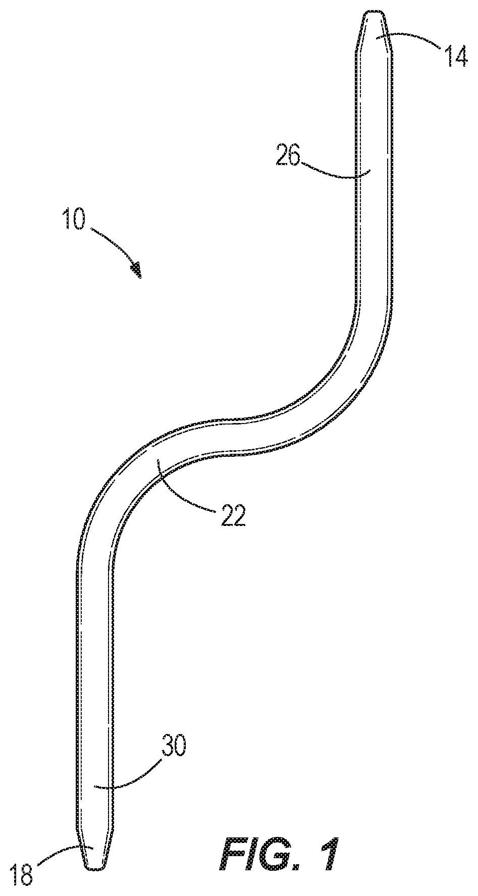
[0012] FIG. 1 is a perspective view of a spring heat pipe according to one embodiment.
[0013] FIG. 2 is a perspective view of a spring heat pipe according to another embodiment, with the inclusion of a flexible bellows.
[0014] FIG. 3 is a perspective view of a heat transfer system according to one embodiment that includes use of multiple spring heat pipes and a heat plate.
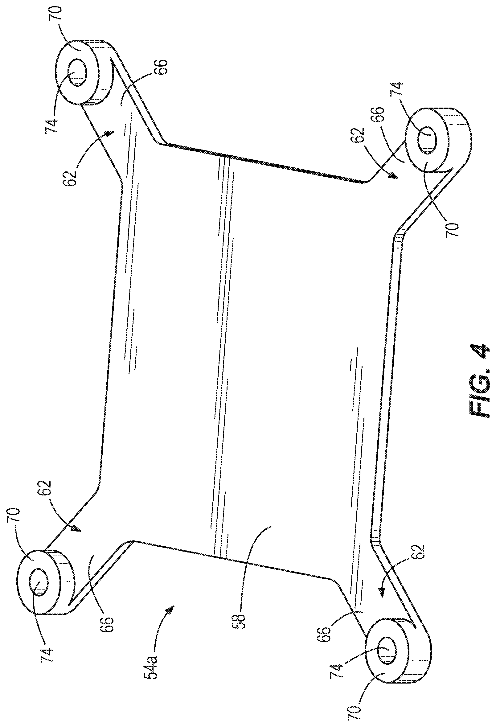
[0015] FIG. 4 is a perspective view of a heat plate according to another embodiment.
DETAILED DESCRIPTION
[0016] Before any embodiments are explained in detail, it is to be understood that embodiments are not limited in their application to the details of construction and the arrangement of components set forth in the following description or illustrated in the following drawings. Other embodiments are possible and embodiments described and illustrated are capable of being practiced or of being carried out in various ways.
[0017] FIG. 1 illustrates one exemplary embodiment of a heat pipe 10 having a first end 14, a second end 18, and an intermediate region 22 disposed between the first and second ends 14, 18 along a length of the heat pipe 10. As illustrated in FIG. 1, in some embodiments the heat pipe 10 has a generally curved, shape or profile (for example an "S" shape). In some embodiments, the first end 14 and the second end 18 extend linearly and parallel to one another, and at least a portion of the intermediate region 22 has a bend that curves between the first end 14 and the second end 18. Other embodiments include different shapes than those illustrated. For example, in some embodiments the heat pipe 10 may have a generally "J" shape, a "U" shape, an "S" shape, a "V" shape, an "L" shape, or various other shapes having for example one, two, or more bends therein.
[0018] The heat pipe 10 includes an evaporator region 26 and a condenser region 30. In the illustrated embodiment, the evaporator region 26 is located at the first end 14 and the condenser region 30 is located at the second end 18, although in other embodiments the evaporator region 26 and/or the condenser region 30 may be located at other areas of the heat pipe 10. For example, the evaporator region 26 and/or the condenser region 30 may overlap with or be located entirely within the intermediate region 22. Alternatively, the evaporator region 26 may be located at the second end 18, and the condenser region 30 may be located at the first end 14.
[0019] The heat pipe 10 may be made of any of a number of suitable materials, including copper, aluminum, stainless steel, titanium, any alloy of these or other metals, or other materials. In some embodiments, the heat pipe 10 includes a hollow, interior vapor chamber sized to contain a working fluid. The working fluid may include, for example, water, methanol, ammonia, or various other types of suitable fluids. The materials selected for the heat pipe 10 and/or the fluids selected for the working fluid may depend, for example, on the environment in which the heat pipe 10 will be used, with some materials and working fluids being more suitable than others, for example, in low-gravity and low-temperature environments.
[0020] In some embodiments, the heat pipe 10 may additionally include a capillary wick structure for moving the working fluid within the heat pipe 10. The capillary wick structure may extend at least partially within the heat pipe 10 from the condenser region 30 to the evaporator region 26, lining an interior surface of the vapor chamber. In some embodiments, the wick structure is located at the evaporator and condenser regions 26, 30, whereas in other embodiments either or both of the evaporator and condenser regions 26, 30 do not include a wick structure. Also in some embodiments, the wick structure extends without interruption along any part or all of the distance between the evaporator and condenser regions 26, 30. The wick structure may be made, for example, from sintered or brazed copper powder or other suitable materials, and/or may include or be defined by axial grooves, one or more mesh objects, or other capillary structures along the interior of the heat pipe 10 that facilitate a wicking action. The capillary wick structure permits the heat pipe 10 to be used in low-gravity environments, and in other applications in which force is needed to move the working fluid in a desired direction (e.g., from the condenser region 30 toward the evaporator region 26).
[0021] When heat is applied to the working fluid at the evaporator region 26, the working fluid evaporates, changing phase into a vapor state. The working fluid flows through the interior vapor chamber in the vapor state from the evaporator region 26 to the condenser region 30. The working fluid then discharges heat at the condenser region 30 as the heat pipe discharges heat to another object or area in thermal communication with the condenser region 30, and changes phase again back to a liquid state at the condenser region 30. The condensed working fluid returns in the liquid state to the evaporator region 26 through the wick structure (when provided in some embodiments).
[0022] In some embodiments the heat pipe 10 has a generally flattened, oval-shaped cross-section, extending along the entirety of the heat pipe 10 from the first end 14 to the second end 18. An example of such a flattened cross-sectional shape is shown in the heat pipes illustrated in FIG. 2, which also applies to any other heat pipes embodiments described and/or illustrated herein. In other embodiments, the heat pipe 10 may have a more circular-shaped cross-section or a cross-section with another shape (e.g., rectangular, etc.). Additionally, in some embodiments, one portion of the heat pipe 10 may have a first cross-sectional shape with another portion of the heat pipe 10 having a different cross-sectional shape. For example, the first end 14 and the second end 18 may each have a generally flattened, oval-shape, or a rectangular cross-sectional shape having at least one generally flat surface, whereas the intermediate region 22 may have a circular-shaped cross-section (see again the heat pipes illustrated in FIG. 2, which include heat pipe sections having generally flattened, oval cross-sectional shapes, and other heat pipe sections having circulate-shaped cross sections).
[0023] In some embodiments, at least a portion of the cross-sectional shape of each heat pipe 10 has a major diameter and a smaller minor diameter. In such embodiments, the heat pipe 10 flexes or bends with greater ease about the major diameter. With reference to the embodiment of FIG. 3, for example (described in greater detail below) in which the illustrated heat pipes have a generally flattened cross-sectional shape along their lengths to define flat top and bottom heat pipe surfaces, the flattened cross-sectional shape better enables each heat pipe 10 to flex in an upward and downward direction. This flexure changes the distance (e.g., vertical distance) between the opposite ends 14, 18 of the heat pipe 10. Stated in another way, this flexure changes the drop or rise of one end 14 of the heat pipe 10 with respect to the other end 18. Although the flattened oval cross-sectional shape of the heat pipe 10 has this feature, it will be appreciated that other heat pipe cross-sectional shapes, including others having a minor axis and a larger major axis about which the heat pipe 10 can more readily flex are possible, such as flattened rectangular cross-sectional shapes, and irregular flattened shapes. In all such embodiments, any portion or all of the length of each heat pipe 10 can be provided with such shapes to enable enhanced flexibility of the heat pipe 10.
[0024] In some embodiments, the heat pipe 10 is shaped so that one portion (e.g., the second end 18) of the heat pipe 10 is manufactured or otherwise formed out of plane with respect to another, different portion (e.g., the first end 14). In this manner, the second end 18 of the heat pipe 10 is generally offset relative to the first end 14 (i.e., has a drop or rise out of the plane in which the first end 14, or second end 18 lie). In other embodiments, when the heat pipe 10 is manufactured, the first and second ends 14, 18 are in a common plane.
[0025] The manufactured heat pipe 10 can function as a curved cantilever, such that when force is applied to deflect the first or second ends 14, 18 of the heat pipe 10 relative to one another, a stored tensile stress or spring-like biasing force is created in the heat pipe 10 that seeks to return the heat pipe 10 to its unstressed state or shape. Consequently, when the deflecting force is removed, the heat pipe 10 returns to its original, unstressed shape or state. In some embodiments, it is particularly advantageous to provide a degree of control over the force exerted by the heat pipe 10 against an object (e.g., computer chip) to be cooled, and/or to enable a range of suitable forces to be applied to such an object. Greater lengths of the heat pipe 10 enable a longer cantilever, and therefore greater control over the amount of force the heat pipe 10 exerts upon the object to be cooled--or greater control over the amount of reaction force exerted by the heat pipe 10 when deflected as described above. In some applications, the ability to apply a specific force or range of forces by the heat pipe 10 upon the object to be cooled is important, such as for applications in which the object to be cooled can be easily damaged. Therefore, the longer cantilevered arm provided by the heat pipe 10 and the flattened cross-sectional shape of the heat pipe 10 better enable the heat pipe 10 to flex, and enable a greater degree of control over the force applied by the heat pipe 10 when flexed.
[0026] Although relatively long heat pipes 10 can be straight in order to provide the force control described above, such a shape can greatly limit the package shape and/or size of devices in which the heat pipe 10 is used. Therefore, some curved heat pipe 10 (e.g., U-shaped or J-shaped heat pipes) can provide a smaller footprint or volume required for the heat pipe 10 in various applications. Similarly, other curved heat pipe shapes (as described herein) can be used to provide similar advantages. In some embodiments for example, the heat pipe 10 may look like a coiled spring, winding around multiple times in the same direction.
[0027] With continued reference to FIG. 1, during manufacture of the heat pipe 10, the heat pipe 10 may first be bent or otherwise shaped (e.g., stamped, etc.) generally into its curved shape. The heat pipe 10 can then be annealed (e.g., in an oven), thereby exposing the heat pipe to an elevated temperature to soften the metal of the heat pipe. The stiffness of the heat pipe 10 can therefore be significantly reduced by being thus annealed, which results in a heat pipe 10 that can be more easily flexed, and that can flex in response to a range of forces under greater control. The annealed feature of the heat pipes 10 can be used as yet another design option (in addition to the longer cantilever of the curved heat pipe 10 and the flattened cross-sectional shape of the heat pipe 10 as discussed above) to better enable the heat pipe 10 to flex, and to enable a greater degree of control over the force applied by the heat pipe 10 when flexed. In some embodiments, the heat pipe 10 may be shaped (e.g., stamped, etc.) into shapes other than that illustrated prior to being annealed.
[0028] In some embodiments, the heat pipe 10 can be further adapted to better enable the heat pipe 10 to flex as desired (again, for a greater degree of control over force applied by the heat pipe 10 when flexed). For example, FIG. 2 illustrates a modified heat pipe 10a that includes a bellows 114 located along the length of the heat pipe 10a. The bellows 114 can be used to alter the spring constant of the heat pipe 10a. While only a single bellows 114 is illustrated, in other embodiments the heat pipe 10a may include a plurality of bellows 114 or bellows regions. Additionally, the heat pipe 10a may include one or more bellows 114 at locations other than that illustrated.
[0029] In some embodiments the heat pipe 10 can be further adapted to better enable the heat pipe 10 to flex as desired by reducing the wall thickness of the heat pipe 10 at one or more locations along the heat pipe 10 in comparison to other (thicker) wall thicknesses at other locations along the heat pipe 10. For example, in one or more regions of the heat pipe 10, the wall of the heat pipe 10 is thinner than adjacent regions along the length of the heat pipe 10 in order to enable the heat pipe 10 to flex in the thinner regions. In each thinner-walled region, the entire circumference of the heat pipe cross-sectional shape can be thinner, or only selected areas of the cross-sectional shape are thinner (e.g., thinner only along flattened sides of the heat pipe 10, thinner only along the major or wider sides of the heat pipe 10, thinner only along the minor or narrower sides of the heat pipe 10, and the like). All such thinned heat pipe regions enables the design of the heat pipe 10 to be tailored to flex as desired for any particular application and to exert a desired force or force ranges upon the heat source 50.
[0030] When a deflecting force is applied to the heat pipe 10 as described above to create a stored tensile stress or spring-like biasing force, the heat pipe 10 will have a spring constant value that depends at least in part upon the size and shape of the heat pipe 10, the materials used to create the heat pipe 10, the amount of deflecting force applied to the heat pipe, and the degree of annealing that occurs during manufacturing of the heat pipe 10.
[0031] With reference now to FIG. 3, one or more of the spring-like heat pipes 10 may be used in conjunction with a heat transfer system 38 to both move heat away from a heat source 50 (e.g., circuit board, shown in phantom in FIG. 3), as well as to help secure one or more of the components of the heat transfer system 38 in place. For example, as illustrated in the embodiment of FIG. 3, the heat transfer system 38 includes a housing 42, which may have any number of a variety of different shapes and sizes (e.g., rectangular-shaped, square-shaped, oval-shaped, irregularly-shaped, etc.) within which are housed multiple heat pipes 10. In the illustrated embodiment of FIG. 3, the housing 42 is a sealed housing, and includes a cover 48 (shown in phantom in FIG. 3) releasably and removably secured to the rest of the housing 42 via screws or other suitable fasteners (not shown) received within fastener holes 92, 96 of the housing 42 and its cover 48, respectively. In the illustrated embodiment of FIG. 3, the fastener holes 92 are located in the corners of the housing 42 and its cover 48, although such fastener holes 92 can be located in any other positions of the housing 42 and its cover 48 as desired. With continued reference to the illustrated embodiment of FIG. 3 by way of example, all components of the heat transfer system 38 are located inside the housing 42 and are sealed within the housing 42. The interior chamber of the housing 42 can have a fluid-tight seal, or in other more demanding environments and applications, the housing 42 can be hermetically sealed, either of which protects the heat source 50 from exposure to damaging environmental conditions such as dust, dirt, and other debris, water, oil or other fluids, and the like. In some embodiments, the housing 42 is a modular assembly that can be installed and removed in a desired application as one integral assembly. Also in some embodiments, other than one or more electrical connectors on the housing 42 that can be connected and disconnected preferably without tools, the entire heat transfer system 38 can be installed in a desired location with the use of one or more releasable fasteners, and can be removed by release of such fastener(s). In this manner, the heat transfer system 38, with its internal heat pipes 10 and heat source 50, can be easily and readily removed and replaced as one integral assembly, in some cases without disturbing the seal that seals the internal components from the surrounding environment.
[0032] As illustrated in FIG. 3, the illustrated housing 42 includes a first mounting wall 48 (e.g., an upper wall including a planar or other-shaped surface, such as defined by the cover 48 in the illustrated embodiment of FIG. 3). The first mounting wall 48 can therefore define at least part of the housing 42. In some cases, at least part of a housing seal (described above) is defined or located between the first mounting wall 48 and the rest of the housing 42. A heat source may be coupled to the first mounting wall 48 and located within the interior of the housing 42. The heat source 50 may be a computer chip, circuit board, sensor, or other electronic component that generates heat. In some embodiments, the heat source 50 is fixed (e.g., via solder, adhesive, fasteners, or other fastening elements or substances) directly to the first mounting wall 48. In yet other embodiments, the heat source 50 merely sits or rests (e.g., loosely) on the first mounting wall 48, without being directly fixed to the first mounting wall 48.
[0033] With continued reference to FIG. 3, the heat transfer system 38 may include multiple heat pipes 10, and may further include a heat transfer plate 54. In some embodiments, fasteners 56 are used to couple the heat transfer plate 54 to the first mounting wall 48. For example, the fasteners 56 can be screws or other threaded fasteners that are received within apertures in the heat transfer plate 54 and that also extend into apertures 90 (e.g., threaded apertures 90) in the cover 48 to couple the heat transfer plate 54 to the first mounting wall 48. The heat source 50 may be positioned above the heat transfer plate 54 (e.g., sandwiched between the first mounting wall 48 and the heat transfer plate 54 and held in place frictionally or with fasteners between the first mounting wall 48 and the heat transfer plate 54). In the illustrated embodiment of FIG. 3, the first ends 14 of the heat pipes 10 are coupled to (e.g., and restrained by) the heat transfer plate 54, and the second ends 18 are spaced away from the first ends 14 in opposite directions within the housing 42. The first ends 14 may be restrained, for example, within channels of the heat transfer plate 54. As also illustrated in FIG. 3, the second end 18 of one of the heat pipes 10 may be located at one end of the housing 42, whereas the second end 18 of the other heat pipe 10 may be located at an opposite end of the housing 42, with the first ends 14 generally being located within a more central region of the housing 42. Additionally, and as illustrated in FIG. 3, in some embodiments the second ends 18 of the heat pipes 10 may be coupled to (e.g., and restrained by) retention structures 44 (e.g., guides, rails, brackets, etc.) within the housing 42. The heat pipes 10 may also be shaped such that the first ends 14 are out of plane (e.g., lower than, with reference to the orientation of FIG. 3) with respect to the second ends 18, and such that the heat pipes 10 provide a natural spring force in at least one direction when installed within the housing 42. For example, the heat pipes 10 may be positioned and shaped such that the first ends 14 exert a reactionary force pulling the heat transfer plate 54 in a direction away from the first mounting wall 48 when the fasteners 56 are tightened to pull the heat plate 54 toward the heat source 50 and the first mounting wall 48. Although in the illustrated embodiment of FIG. 3 the second ends 18 of the heat pipes 10 are secured to the housing 42 opposite the first mounting wall 48 in other embodiments the second ends of the heat pipes 10 are instead secured to the first mounting wall 48 and are shaped to exert the same or similar reactionary force as described above when the fasteners 56 are tightened to pull the heat plate 54 toward the heat source 50 and the first mounting wall 48 Various other embodiments include differently shaped housings, differently shaped heat pipes, differently shaped heat transfer plates, and/or different coupling locations for the ends of the heat pipes and the heat transfer plates within the housing 42 than that illustrated.
[0034] FIG. 4 illustrates a heat transfer plate 54a according to a different embodiment. As illustrated in FIG. 4, in some embodiments the heat transfer plate 54a may include an intermediate region 58 that is generally sized and shaped to fit over the heat source 50, and to at least partially cover (e.g., substantially or entirely cover) the heat source 50, thereby sandwiching the heat source 50 between the intermediate region 58 of the heat transfer plate 54a and, for example, the first mounting wall 48. In the illustrated embodiment of FIG. 4, the intermediate region 58 is a planar region having a generally rectangular shape, although in other embodiments, part or all of the intermediate region 58 may be non-planar, and/or may have a different shape or size than that illustrated. Additionally, one or more areas of the intermediate region 58 may be flexible (e.g., made of thinner material than other areas of the intermediate region 58), so as to facilitate bending and/or shaping of the heat transfer plate 54a during use to conform to and accommodate the shape and size of the heat source 50.
[0035] As also illustrated in FIG. 4, the heat transfer plate 54a may further include at least one mounting region 62. In the illustrated embodiment of FIG. 4, the heat transfer plate 54a includes four mounting regions 62, each mounting region 62 being disposed generally at a corner of the intermediate region 58. Other embodiments may include different numbers and locations of mounting regions 62 than that illustrated. With continued reference to FIG. 4, each mounting region 62 may include an arm 66 by which the heat transfer plate 54a is connected for example to the first mounting wall 48. The arms 66 can have any shape and size suitable for this purpose, and can be relatively stiff or may flex when secured to the first mounting wall 48. For example, the arms 66 in the illustrated embodiment of FIG. 4 are integral with the heat transfer plate 54a, and each include a thickened, distal end 70 at which the heat transfer plate 54a may be connected, for example, to the first mounting wall 48. The heat transfer plate 54a (and more particularly, the arms 66 of the heat transfer plate 54 in the illustrated embodiment of FIG. 4), can be provided with apertures 74 extending through the heat transfer plate 54 for attachment to the first mounting wall 48. In the illustrated embodiment of FIG. 4, the apertures 74 extend through the distal end 70 of each arm 66, but can be located elsewhere in the heat transfer plate 54a in other embodiments. Any number of apertures 74 can be used to secure the heat transfer plate 54 to, for example, the first mounting wall 48, and in some embodiments can be internally threaded for mating with fasteners.
[0036] In some embodiments, the heat transfer system 38 may further include at least one fastener that is at least partially received through each aperture 74 of the heat transfer plate 54a. For example, the heat transfer system 38 may include four fasteners, each of which is a threaded fastener for being threaded into a respective one of the threaded apertures 74. Each fastener can have a fastener head (not shown) disposed outside the housing 42 for access and tightening or loosening by a user, and a fastener body (also not shown) that extends through an aperture 90 (see FIG. 3) in the first mounting wall 48 and into the threaded aperture 74. In this manner, after the first mounting wall 48 (with the heat source 50 and any other components thereon) has been assembled to the rest of the housing 42 (at which time access to the heat source 50, the heat transfer plate 54, 54a, the heat pipes 10, and other components within the housing 42 is limited or impossible), the fasteners can still be adjusted from outside the housing 42 to tighten or loosen the heat transfer plate 54, 54a against the heat source 50. In some embodiments, the apertures 90 through which the fasteners pass can each include a conventional seal (not shown) to preserve the fluid-tight or hermetic seal of the housing 42 described above. Such adjustment can also therefore flex the heat pipes 10 as described elsewhere herein without requiring user access to the inside of the housing 42.
[0037] The heat transfer system 38 may further include at least one biasing member (e.g., compression spring) disposed between the head of the fastener 56 and the exterior of the first mounting wall 48. The biasing members can exert a biasing force on the fasteners 56 in a direction away from the first mounting wall 48 and the heat transfer plate 54, 54a, and can be used to prevent excessive force exerted upon the heat transfer plate 54, 54a and the heat source 50 by overtightening the fasteners 56. The biasing members 56, in combination with the threaded connection between the fasteners 56 and the mounting regions 62 (see FIG. 4, by way of example), may thus exert a pulling force on the heat transfer plate 54, 54a toward the first mounting wall 48, thereby pressing the plate's intermediate region 58 (again, see FIG. 4 bay way of example) against the heat source 50. This force creates a thermal bridge between the heat source 50 and the heat transfer plate 54, 54a. In some embodiments, this force can also be used to secure the heat source 50 in place (e.g., frictionally) between the heat transfer plate 54, 54a and the first mounting wall 48. In other embodiments, the biasing members may be omitted, in which case the fasteners 56 may still be tightened to pull the heat transfer plate 54 against the heat source 50 to secure the heat source 50 in place by sandwiching the heat source 50 between the heat transfer plate 54, 54a and the first mounting wall 48.
[0038] In some embodiments, the evaporator region 26 of each heat pipe 10 is coupled to or otherwise positioned on heat transfer plate 54, 54a (e.g., the intermediate region 58 of the heat transfer plate 54a in the illustrated embodiment of FIG. 4) opposite the heat source 50. In these and other embodiments (and as described above), the heat pipes 10 can take any shape desired. In those embodiments in which the heat transfer system 38 includes two or more heat pipes 10, significant space savings can be achieved while still enjoying the benefits of a long cantilever arm for each heat pipe by utilizing heat pipes that are curved, and that in some embodiments have heat pipes shaped and positioned to be at least partially nested or received within one another. For example, in some embodiments the evaporator regions 26 of two "U"-shaped or "J"-shaped heat pipes 10 are oriented adjacent one another such that the first ends 14 extend generally parallel to and are spaced apart from one another by a first distance, and such that the second ends 18 (that include the condenser regions 30) extend generally parallel to and are spaced apart from one another by a second distance, the second distance being greater than the first distance. In other embodiments, the distances between the heat pipes 10 may vary as needed for any particular application or environment. The ends of the heat pipes 10 also may face in opposite directions, such that the evaporator ends 14 extend in opposite directions with respect to one another to their respective terminal ends, and the condenser ends 18 extend in opposite directions with respect to one another to their respective terminal ends. Portions of the heat pipes 10 may extend in an overlapping configuration, where the first end 14 of one heat pipe 10 is disposed in the space defined between the first end 14 and the second end 18 of the other heat pipe 10, and vice versa. Such arrangements can define an efficient use of space within the housing 42, while also providing enhanced cooling of the heat source 50 (i.e., by multiple heat pipes 10) in a relatively small area.
[0039] In some embodiments, the first ends 14 are fixed (e.g., via brazing, welding, soldering, etc.) to the heat transfer plate 54, 54a. In other embodiments, the first ends 14 are disposed inside or beneath a portion of the heat transfer plate 54, 54a. For example, the intermediate region 58 of the heat transfer plate 54a in FIG. 4 may include one or more areas (e.g., raised areas, recesses, coverings, etc.) that define openings or chambers for receiving the first ends 14 of the two heat pipes 10. The first ends 14 may slide into these areas, and be retained therein frictionally, by brazing, welding, soldering, adhesive, fasteners, or in any other suitable manner. In some embodiments, surfaces of the first ends 14 of the heat pipes 10 are flush with the surrounding portions of the heat transfer plate 54, 54a, or are recessed within the heat transfer plate 54, 54a. In such embodiments, the heat transfer plate 54, 54a (and in some cases, the first ends of 14 of the heat pipes 10 as well) present a collective surface that is relatively flat, and that can therefore define a better thermal interface with the heat source 50 to which the heat transfer plate 54, 54a faces. In this regard, the first ends 14 of the heat pipes 10 and adjacent portions of the heat transfer plate 54, 54a can be brought into direct thermal contact with the heat source 50 in some embodiments, including those in which the first ends 14 of the heat pipes 10 are in or on the same side of the heat transfer plate 54, 54a that faces the heat source 50.
[0040] In some embodiments, the second ends 18 of the two heat pipes 10 are each coupled (e.g., fixed via brazing, welding, soldering, etc.) to a second mounting wall 102 of the housing 42. The first end 14 of each heat pipe 10 may be movable to different positions with respect to the second end 18 of the heat pipe 10. The second mounting wall 102 may be located opposite the first mounting wall 48, although in other embodiments the second ends 18 of either or both heat pipes 10 are instead coupled to side walls of the housing 42, or to other portions of the first mounting wall 48, depending at least in part upon the shape of the heat pipes 10. The first mounting wall 48 and the second mounting wall 102, along with side walls, may define a sealed interior cavity 110 of the housing 42. The interior cavity 110 may be located between the first mounting wall 48 and the second mounting wall 102. Other embodiments may include different numbers of mounting walls and side walls than that illustrated, as well as different shapes, sizes, and dimensions of walls than that illustrated. In some embodiments, the entirety of the first and second heat pipes 10, the entirety of the heat transfer plate 54, 54a, and the entirety of the heat source 50 may each be disposed within the sealed interior cavity 110.
[0041] In some embodiments, the spring-like heat pipes 10 exert a biasing force in a direction away from the first mounting wall 48 and heat source 50 when the heat pipes 10 are in thermal communication with the heat source 50. For example, the heat pipes 10 may be placed in a stressed, tensile state when coupled to the heat transfer plate 54, 54a (and for example to the second mounting wall 102 with the first ends 14 of the heat pipes 10 out-of-plane with respect to the second ends 18 of the heat pipes 10, and while the heat pipes 10 are in conductive thermal communication with the heat source 50. In such a state, the heat pipes 10 exert a restorative force in a direction pulling the heat transfer plate 54, 54a away from the first mounting wall 48. In other words, in an unstressed state, an offset distance of the first end 14 of each heat pipe 10 with respect to the second end 18 would be less than in the stressed state (the distance between the ends 14, 18 of the heat pipe 10 may be zero if the first and second ends 14, 18 are in a common plane in the unstressed state). Put another way, the offset distance between the first and second ends 14, 18 of the heat pipe 10 is greater in a stressed state than in an unstressed state, thereby creating a stored spring-like biasing force in the heat pipe 10. Thus, when stressed, the first ends 14 of the heat pipes 10 exert a constant force on the heat transfer plate 54, 54a in a direction away from the first mounting wall 48 (and for example toward the opposite second mounting wall 102, while the fasteners 56 and/or biasing members (if used) exert an opposite force on the heat transfer plate 54, 54a toward the first mounting wall 48. In this manner, the fasteners 56 can be adjusted with significant precision to offset a desired amount of restorative force of the heat pipes 10 urging the heat pipes 10 to return to their unstressed state. This precision is in contrast to systems in which the adjustment of force between the heat pipe(s) 10 and the heat source 50 is either impossible, or is much more difficult to perform.
[0042] In some embodiments, the heat pipes 10 may initially be in an unstressed state when coupled to the heat transfer plate 54, 54a (and for example to the second mounting wall 102). The heat pipes 10 in such a state can be offset as described and illustrated herein, or in some embodiments can lie in the same plane. In some embodiments, the fasteners 56 may then be tightened (e.g., to varying degrees as desired), pulling the heat transfer plate 54, 54a toward the first mounting wall 48 and placing the heat pipes 10 in a stressed state by pulling the first ends 14 of the heat pipes 10 away from the fixed second ends 18 and toward the first mounting wall 48. As a result, when so stressed, the first ends 14 of the heat pipes 10 exert a constant spring-like biasing force on the heat transfer plate 54, 54a in a direction away from the first mounting wall 48 while the fasteners 56 and/or biasing members (if used) exert an opposite force on the heat transfer plate 54, 54a toward the first mounting wall 48.
[0043] In other embodiments, the heat pipes 10 exert a biasing force in a direction toward the first mounting wall 48. In such embodiments, in the unstressed state, the first end 14 of each heat pipe 10 can be offset from the second end 18. In the stressed assembled state, the first end 14 of each heat pipe 10 can be positioned at an offset distance from the second end 18 of the heat pipe 10 that is less than the initial offset distance (in the unstressed state) so that the first end 14 seeks to return to its initial position farther away from the first end 18 and closer toward the first mounting wall 48. In such cases, the heat pipes 10 can exhibit a spring or biasing force on the heat transfer plate 54, 54a in a direction toward the first mounting wall 48.
[0044] In embodiments described above and illustrated in the figures, the first and second ends 14, 18 of the heat pipes 10 are offset in an unstressed state, and are either offset in the stressed and assembled state or lie in the same plane in the stressed and assembled state. In other embodiments, the heat pipes 10 lie in the same plane in the unstressed state, and are offset in the stressed and assembled state. In still other embodiments, the heat pipes 10 are offset in one direction in the unstressed state, and are offset in the opposite direction in the stressed and assembled state, wherein the first end 14 of each heat pipe flexes from an unstressed and offset position with respect to the second end 18, toward and past a co-planar state with the second end 18, and on to a stressed an offset position with respect to the second end 18.
[0045] The various embodiments of heat pipe 10 flexure (i.e., relative positions of the first and second ends 14, 18 when unstressed and stressed) described herein can be selected as to achieve a desired profile of force exerted upon the heat source 50 (e.g., when the fasteners 56 are tightened). For example, the range of forces exerted by the heat pipes 10 as they are flexed toward a co-planar position can be significantly different from the range of forces exerted by the heat pipes 10 as they are flexed away from a co-planar position. The force profile (change in force as a function of changing heat pipe flexure) can be selected by the designer of the heat transfer system 38 based upon the design specifications/requirements and user preferences of the heat transfer system 38.
[0046] With continued reference to FIGS. 1-4, during operation, the heat source 50 generates heat that is conducted through the heat transfer plate 54, 54a to the evaporator regions 26 of the heat pipes 10 (the heat pipes 10 being in thermal communication with the heat source 50). In some embodiments, the heat is transferred directly from the heat source 50 to the heat pipes 10 (which can include conductive heat transfer through braze, weld, solder, tape, or other connecting material, and/or thermal grease, oil, paste, or other thermal interface material). In other embodiments (dependent at least in part upon the relative position of the heat pipes 10 with respect to the heat transfer plate 54, 54a), the heat is transferred first into the heat transfer plate 54, 54a and then into the heat pipes 10, or is transferred both directly into the heat pipes 10 from the heat source 50 and indirectly into the heat pipes 10 through the heat transfer plate 54, 54a.
[0047] The heat is then transferred to and absorbed by the working fluid inside of the heat pipes 10 in the evaporator regions 26, causing the working fluid to change phase and vaporize in the vapor chamber. The vaporized working fluid then flows along the lengths of the heat pipes 10 within the vapor chamber, through the intermediate (e.g., curved) regions 22, and finally to the condenser regions 30 where the working fluid then changes phase again and condenses back into a liquid state. The heat released at the condenser regions 30 when the vaporized working fluid changes phase to condense into a liquid state may be dissipated, for example, at least partially to the second mounting wall 102, to the interior cavity 110 of the housing 42, and/or to one or more additional heat transfer devices (not illustrated) that are thermally coupled to the condenser regions 30. Once the heat has been dissipated, the working fluid condensate flows back from the condenser regions 30 of the heat pipes 10 (e.g., along the wick structure) to the evaporator regions 26, where the working fluid then again absorbs heat generated by the heat source 50, and the heat transfer cycle repeats.
[0048] As described above, the heat pipes 10 may be oriented so that their respective first ends 14 point in opposite directions to one another, and/or their respective second ends 18 point in opposite directions to one another. For example, heat pipes 10 with J-shaped profiles may face in opposite directions. Thus, as illustrated in FIG. 3, heat generated by the heat source 50 absorbed into one of the heat pipes 10 is conducted away toward one side and/or corner of the housing 42, and heat generated by the heat source 50 absorbed into the other heat pipe 10 is conducted away toward an opposite side and/or corner of the housing 42. This bi-directional heat conduction facilitates rapid heat dissipation of heat away from the heat source 50. Additionally, because the second ends 18 of the heat pipes 10 are offset from the respective first ends 14 in some embodiments, heat generated by the heat source 50 is conducted away from the heat source 50 both vertically, as well as laterally, further facilitating a rapid dissipation of heat away from the heat source 50.
[0049] In some embodiments, only a single heat pipe 10 is used within the housing 42. The heat pipe 10 may have an "S" or "J" shape, or may have any variety of different shapes as required by the particular application or environment. In other embodiments, more than two (e.g., three, four, etc.) heat pipes 10 may be used within the housing 42, again each having an "S" or "J" shape or other different shapes as required by the particular application or environment. The shape of each heat pipe 10 may also be different within the same housing 42. For example, one heat pipe 10 may have a "J" shape, whereas another heat pipe 10 may have a "U" shape or "S" shape, etc.
[0050] In some embodiments a heat transfer system includes a housing, and annealed heat pipes coupled to the housing. Each of the heat pipes has an evaporator region and a condenser region separated by an intermediate region defining at least one reversal of direction of the annealed heat pipe. The evaporator and condenser regions of a first one of the heat pipes both face in a first direction. The evaporator and condenser regions of a second one of the heat pipes both face in a second direction that is opposite to the first direction. The heat transfer system may otherwise be similar or identical, for example, to the heat transfer system 38 described above and illustrated in FIG. 3. For example, in some embodiments first and second ends of the heat pipes are offset in an unstressed state, and are either offset in the stressed and assembled state or lie in the same plane in the stressed and assembled state. In other embodiments, the heat pipes lie the same plane in the unstressed state, and are offset in the stressed and assembled state. In still other embodiments, the heat pipes are offset in one direction in the unstressed state, and are offset in the opposite direction in the stressed and assembled state. The first end of each heat pipe may flex from an unstressed and offset position with respect to the second end, toward and past a co-planar state with the second end, and on to a stressed an offset position with respect to the second end. Additionally, in some embodiments the heat pipes are coupled to (e.g., restrained by) a heat plate, similar to the heat plate 54 or 54a.
[0051] In some embodiments, the evaporator region and the condenser region of a first heat pipe are out of plane with respect to one another in an unstressed state of the first heat pipe. The evaporator region and the condenser region of a second one of the heat pipes may also be out of plane with respect to one another in an unstressed state of the second heat pipe. The evaporator regions of the first and second heat pipes may extend parallel to one another, and the condenser regions of the first and second heat pipes may extend parallel to one another.
[0052] In some embodiments, the evaporator regions of a first heat pipe and second heat pipe are spaced from each other by a first distance, and the condenser regions of the first and second heat pipes are spaced from each other by a second distance. The second distance is greater than the first distance. In other embodiments the second distance is less than the first distance, or is equal to the first distance.
[0053] Although various embodiments have been described in detail with reference to certain examples illustrated in the drawings, variations and modifications exist within the scope and spirit of one or more independent aspects as described and illustrated.
* * * * *
D00000
D00001
D00002
D00003
D00004
XML
uspto.report is an independent third-party trademark research tool that is not affiliated, endorsed, or sponsored by the United States Patent and Trademark Office (USPTO) or any other governmental organization. The information provided by uspto.report is based on publicly available data at the time of writing and is intended for informational purposes only.
While we strive to provide accurate and up-to-date information, we do not guarantee the accuracy, completeness, reliability, or suitability of the information displayed on this site. The use of this site is at your own risk. Any reliance you place on such information is therefore strictly at your own risk.
All official trademark data, including owner information, should be verified by visiting the official USPTO website at www.uspto.gov. This site is not intended to replace professional legal advice and should not be used as a substitute for consulting with a legal professional who is knowledgeable about trademark law.