Electromagnetic Sensor With Probe And Guide Sensing Elements
Duindam; Vincent
U.S. patent application number 16/875747 was filed with the patent office on 2020-09-03 for electromagnetic sensor with probe and guide sensing elements. The applicant listed for this patent is INTUITIVE SURGICAL OPERATIONS, INC.. Invention is credited to Vincent Duindam.
| Application Number | 20200275860 16/875747 |
| Document ID | / |
| Family ID | 1000004830152 |
| Filed Date | 2020-09-03 |


| United States Patent Application | 20200275860 |
| Kind Code | A1 |
| Duindam; Vincent | September 3, 2020 |
ELECTROMAGNETIC SENSOR WITH PROBE AND GUIDE SENSING ELEMENTS
Abstract
A medical system comprises a probe comprising a coil and a terminal distal end. The medical system further comprises a guide instrument comprising a terminal distal end, a sensor, and a lumen sized to receive the probe. The probe is configured to be inserted through the lumen to reach a worksite. At the worksite, the terminal distal end of the probe is configured to reach at least the terminal distal end of the guide instrument. The medical system further comprises processing hardware configured to receive a first signal from the coil and to receive a second signal from the sensor.
| Inventors: | Duindam; Vincent; (San Francisco, CA) | ||||||||||
| Applicant: |
|
||||||||||
|---|---|---|---|---|---|---|---|---|---|---|---|
| Family ID: | 1000004830152 | ||||||||||
| Appl. No.: | 16/875747 | ||||||||||
| Filed: | May 15, 2020 |
Related U.S. Patent Documents
| Application Number | Filing Date | Patent Number | ||
|---|---|---|---|---|
| 14802199 | Jul 17, 2015 | 10682070 | ||
| 16875747 | ||||
| 13889984 | May 8, 2013 | |||
| 14802199 | ||||
| 13274237 | Oct 14, 2011 | 9387048 | ||
| 13889984 | ||||
| 61646619 | May 14, 2012 | |||
| Current U.S. Class: | 1/1 |
| Current CPC Class: | A61M 2025/0166 20130101; A61B 2034/2051 20160201; A61B 5/065 20130101; A61B 5/6852 20130101; A61M 25/09 20130101; A61B 5/062 20130101; A61B 34/20 20160201; A61B 2034/302 20160201 |
| International Class: | A61B 5/06 20060101 A61B005/06; A61M 25/09 20060101 A61M025/09; A61B 34/20 20060101 A61B034/20 |
Claims
1-23. (canceled)
24. A medical system comprising: a probe comprising: a coil; and a terminal distal end; a guide instrument comprising a terminal distal end, a sensor, and a lumen sized to receive the probe, wherein the probe is configured to be inserted through the lumen to reach a worksite, and wherein at the worksite, the terminal distal end of the probe is configured to reach at least the terminal distal end of the guide instrument; and processing hardware configured to receive a first signal from the coil and to receive a second signal from the sensor.
25. The medical system of claim 24, wherein the second signal received from the sensor indicates a pointing direction of the guide instrument.
26. The medical system of claim 24, wherein the processing hardware is configured to use the first signal and the second signal to determine six degrees of freedom of the probe.
27. The medical system of claim 24, wherein the processing hardware is further configured to use the first signal and the second signal to determine a roll angle of the probe.
28. The medical system of claim 27, wherein the probe comprises a surgical tool, a camera, or a vision system.
29. The medical system of claim 24, wherein the processing hardware is configured to receive the first signal and the second signal when the probe is at the worksite.
30. The medical system of claim 29, wherein after the processing hardware receives the first signal and the second signal, the probe is configured to be removed from the lumen of the guide instrument.
31. The medical system of claim 24, wherein the sensor comprises a second coil, and wherein a normal direction of the coil is different from a normal direction of the second coil.
32. The medical system of claim 31, wherein the normal direction of the coil is perpendicular to the normal direction of the second coil.
33. The medical system of claim 24, wherein the probe comprises a surgical tool, a camera, or a vision system.
34. The medical system of claim 24, wherein the guide instrument comprises a catheter, an endoscope, a bronchoscope, or a cannula.
35. The medical system of claim 24, wherein: the sensor comprises a second coil; and the processing hardware is configured to receive the second signal from the second coil and employ the second signal as an indication of a pointing direction of the guide instrument.
36. The medical system of claim 35, further comprising a field generator configured to generate a varying magnetic field that induces the first signal in the coil and induces the second signal in the second coil.
37. The medical system of claim 24, wherein the coil comprises wire that is wound in a plurality of loops collectively defining a first core extending along a lengthwise direction of the probe, wherein each of the loops defines a first normal direction that is at a non-zero angle relative to the lengthwise direction.
38. The medical system of claim 24, wherein the guide instrument further comprises: a proximal section; a steerable distal section; and a plurality of actuation cables extending from the proximal section into the steerable distal section, wherein each actuation cable of the plurality of actuation cables is configured to actuate the steerable distal section.
39. The medical system of claim 38, further comprising an actuator, wherein each actuation cable of the plurality of actuation cables is coupled to the actuator, and wherein the actuator is configured to actuate the steerable distal section of the guide instrument by actuating at least one actuation cable of the plurality of actuation cables.
40. The medical system of claim 24, wherein: the sensor comprises a shape sensor; and the processing hardware is configured to receive the second signal from the shape sensor and employ the second signal as an indication of a pointing direction of the guide instrument.
41. The medical system of claim 24, wherein a roll axis of the probe extends in a direction normal to the sensor.
42. The medical system of claim 24, further comprising a medical tool sized to extend within the lumen of the guide instrument, wherein a terminal distal end of the medical tool is configured to reach at least the terminal distal end of the guide instrument.
43. The medical system of claim 42, wherein the medical tool includes a second coil, and wherein the processing hardware is configured to receive a third signal from the second coil and to use both the third signal from the second coil and the second signal from the sensor to determine a roll angle of the medical tool.
Description
CROSS-REFERENCE TO RELATED APPLICATIONS
[0001] This patent document claims the priority of U.S. provisional Pat. App. No. 61/646,619, filed May 14, 2012, and is a continuation-in-part and claims benefit of the earlier filing date of U.S. patent application Ser. No. 13/274,237, filed Oct. 14, 2011, both of which are hereby incorporated by reference in their entirety.
BACKGROUND
[0002] Minimally invasive medical devices that navigate natural body lumens need to be small enough to fit within the lumens. Lung catheters, for example, which may be used to perform minimally invasive lung biopsies or other medical procedures, may need to follow airways that decrease in size as the catheter navigates branching passages. To reach a target location in a lung, a catheter may follow passages having diameters as small as 3 mm or less. Manufacturing a catheter that is sufficiently small and includes the mechanical structures and sensors for remote or robotic operation can be challenging.
[0003] Electromagnetic sensors (EM) sensors can measure the position and orientation of a portion of a medical instrument. EM sensors are particularly suitable for minimally invasive medical instruments because EM sensors can combine high global accuracy with a small diameter package size. During EM sensor operation, a generator external to a patient can produce a well-controlled, time-varying magnetic field, and in response, one or more coils of an EM sensor in or on a portion of the medical instrument produce induced electrical signals. In particular, time variations in the magnetic field induce currents in the coils of the EM sensor, and the pose of each coil can be partially determined from knowledge of the generated magnetic field and the geometry of the coil. A single coil can be used, for example, to measure a position and a pointing direction, e.g., pitch and yaw angles, but a cylindrically symmetrical coil is unable to distinguish roll angles about the symmetry axis of the coil. Accordingly, EM sensors employing a single cylindrical coil have been used as 5-Degree-of-Freedom (5-DoF) sensors. To additionally measure the roll angle, a 6-DoF EM sensor generally requires two coils having symmetry axes that are not parallel, e.g., perpendicular symmetry axes.
[0004] The long, thin shape typical of 5-DoF EM sensors fits well with minimally invasive medical instruments or tools, which often have long and thin extensions. However, with the central axis of a single coil sensor aligned with the roll axis of an instrument, such 5-DoF EM sensors cannot measure the roll angle of the instrument. While some symmetric instruments such as needles may not require roll angle measurements, many instruments require knowledge of the roll angle of the instrument, particularly for robotic control. Measurement of the roll angle may require a 6-DoF sensor that includes two coils. For example, to create a 6-DoF EM sensor, two 5-DoF EM sensors may need to be placed perpendicular or at a non-zero angle to each other, which creates a much larger sensor package. If each 5-DoF sensor has a cylindrical shape about 1 mm in diameter and about 10 mm long, the 6-Dof sensor containing two 5-DoF sensors may be up to 10.times.10.times.1 mm. While the 1 mm diameter of a 5-DoF EM sensor may fit within a small, e.g., 3 mm diameter, instrument, a 10-mm wide 6-DoF EM sensor may not fit in a small instrument.
SUMMARY
[0005] In accordance with an aspect of the invention, a small diameter EM sensor can include a coil with windings that define areas with a normal direction at a significant angle to the symmetry or long axis of the coil. As a result, the magnetic axis of an EM sensor that extends along a length of an instrument may be at an angle to the roll axis of the instrument to enable the sensor to measure a roll angle of the instrument, while still providing a narrow diameter package.
[0006] In one specific embodiment, a sensing system uses a coil including wire that is wound in loops around an axis, and each of the loops defines an area that has a normal direction at a non-zero, angle relative to the axis of the coil.
[0007] In another embodiment, a sensing system includes a coil and sensor logic. The coil includes wire that is wound in loops about an axis, and the loops define respective areas that have a normal direction at a non-zero angle relative to the axis of the coil. The sensor logic is coupled to the coil and configured to use an electrical signal induced in the coil in determining a measurement of a roll angle about the axis of the coil.
[0008] In yet another embodiment, a medical system includes a probe and optionally a guide instrument (e.g., catheter, bronchoscope, or endoscope) with a lumen sized for guiding the probe. A probe coil is in the probe and includes wire that is wound in loops collectively defining a first core that extends in a lengthwise direction of the probe. However, each of the loops in the probe coil defines an area that has a normal direction at a non-zero angle relative to the length of the probe. A secondary sensor (e.g., an electromagnetic sensor, shape sensor, gravity sensor, visualization sensor, and/or angular sensor(s), among others) included in the medical system can provide supplemental orientation information to be used with the probe coil signals to determine a roll angle of the probe. For example, a secondary sensor such as a coil could be positioned in a wall of a guide instrument for the probe, such that each of the loops of the guide instrument coil defines an area that has a second normal direction. Sensor logic that is coupled to receive induced signals from the probe coil and the guide instrument coil can then determine a roll angle of the probe from the induced signals.
BRIEF DESCRIPTION OF THE DRAWINGS
[0009] FIG. 1 shows a minimally invasive medical instrument that uses an electromagnetic sensor that includes an off-axis coil.
[0010] FIG. 2 shows an embodiment of a steerable segment that can be employed in the system of FIG. 1.
[0011] FIG. 3 shows sensing coils that can be employed in electromagnetic sensors in medical systems in some embodiments of the invention.
[0012] FIG. 4 shows a cross-section of an off-axis coil that can be used in an electromagnetic sensor.
[0013] FIG. 5 illustrates the geometry of one embodiment of an electromagnetic sensing system that uses an off-axis coil in a magnetic field for measurements of five degrees of freedom.
[0014] FIGS. 6A and 6B show alternative configurations of electromagnetic sensor systems using at least one off-axis coil for measurement of six degrees of freedom.
[0015] FIG. 7 shows a medical system capable of using a coil in a probe and a secondary sensor to measure six degrees of freedom including a roll angle of the probe.
[0016] Use of the same reference symbols in different figures indicates similar or identical items.
DETAILED DESCRIPTION
[0017] An EM sensor can employ an off-axis coil, which is a coil wound so that areas respectively defined by individual loops have a normal direction that is off-axis from the length of the coil. As a result, an effective area for magnetic flux in the off-axis coil has a normal direction that is also off-axis from the length of the coil. A magnetic field applied to an off-axis coil can be varied to induce an electrical signal that depends on the normal direction instead of about the long axis of the coil. Such a coil can thus be used in a small-diameter medical instrument to measure a roll angle about the long axis of the coil.
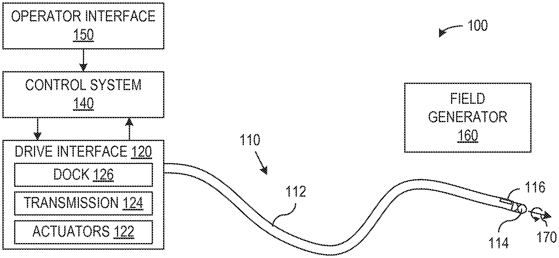
[0018] FIG. 1 schematically illustrates a medical system 100 in accordance with one embodiment of the invention. In the illustrated embodiment, medical system 100 includes a medical device 110, a drive interface 120, a control system 140, an operator interface 150, and a field generator 160 for a sensing system.
[0019] Medical device 110, in the illustrated embodiment, may be a flexible device such as a catheter, bronchoscope, endoscope, or cannula that includes a main shaft 112 with one or more lumens. For example, main shaft 112 may include a main lumen sized to accommodate interchangeable probes. Such probes can include a variety of a camera or vision systems, biopsy tools, cutting tools, clamping tools, sealing tools, suturing tools, stapling tools, cautery tools, therapeutic or diagnostic material delivery tools, or any other surgical instruments. The probes used in device 110 may be robotically operated, for example, using actuating tendons (not shown) that run the length of the probe. Additionally, main shaft 112 may incorporate one or more steerable sections 114 that are similarly operable using actuating tendons that attach to steerable section 114 and run from steerable section at the distal end of main shaft 112, through main shaft 112, to the proximal end of main shaft 112.
[0020] An exemplary embodiment of device 110 may be a lung catheter, bronchoscope or endoscope, where device 110 would typically be about 60 to 80 cm or longer. During a medical procedure, at least a portion of main shaft 112 and all of steerable section 114 may be inserted along a natural lumen such as an airway of a patient, and drive interface 120 may operate steerable section 114 by pulling on actuating tendons, e.g., to steer device 110 during insertion or to position steerable section 114 for a procedure.
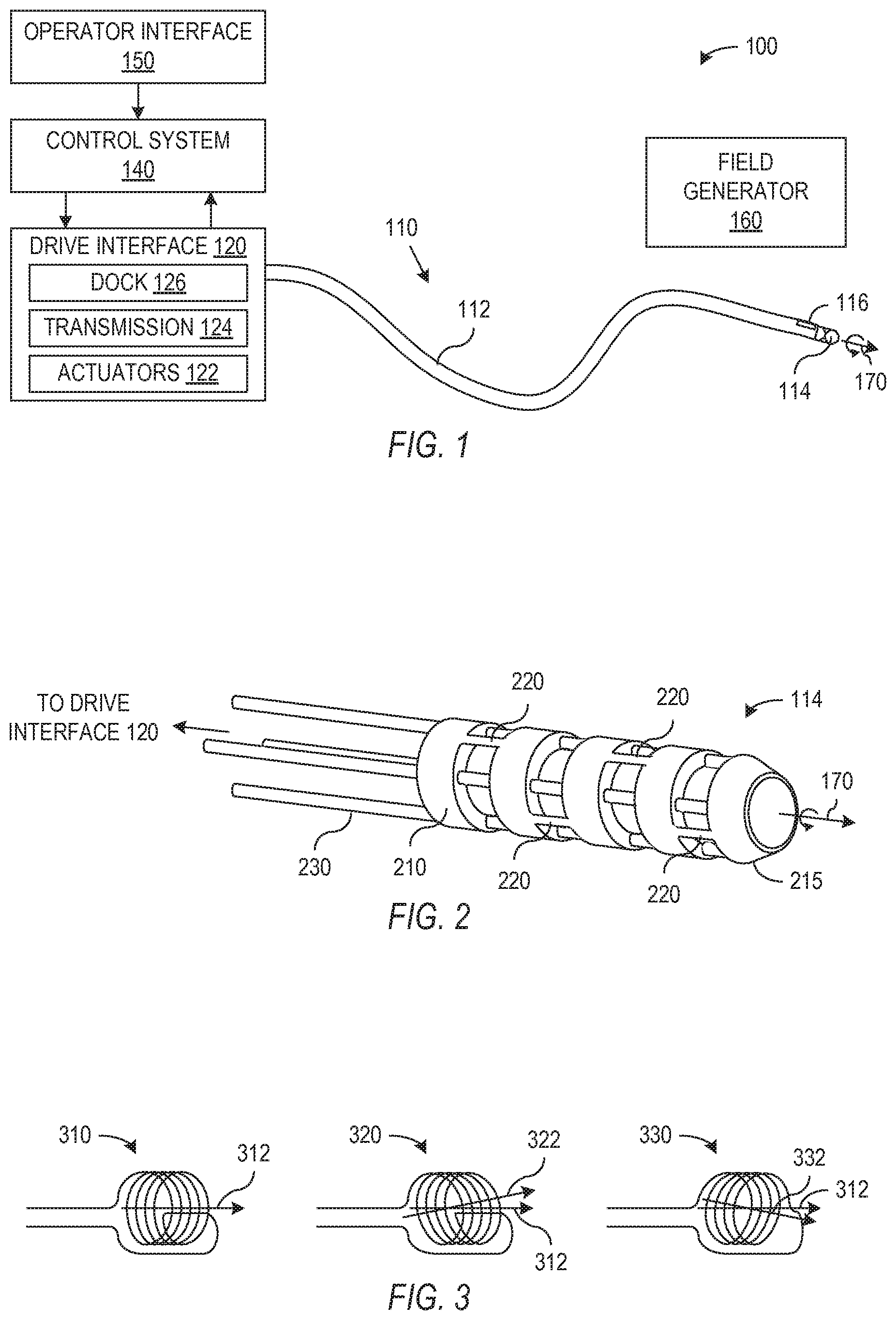
[0021] Steerable section 114 is remotely controllable and particularly has a pitch and a yaw that can be controlled using actuating tendons, e.g., pull wires or cables, and may be implemented as a multi-lumen tube of flexible material such as Pebax. In general, steerable section 114 may be more flexible than the remainder of main tube 112, which assists in isolating actuation or bending to steerable section 114 when drive interface 120 pulls on the actuating tendons. Device 110 can also employ additional features or structures such as use of Bowden cables for actuating tendons to prevent actuation from bending the more proximal portion of main tube 112. In general, the actuating tendons are located at different angles about a roll axis 170 of steerable section 114. For example, FIG. 2 shows one specific embodiment in which steerable section 114 is made from a tube 210 that may be cut to create flexures 220. Tube 210 in the illustrated embodiment defines a main lumen for a probe system and smaller lumens for actuating tendons 230. In the illustrated embodiment, four actuating tendons 230 attach to a distal tip 215 of steerable section 114 at locations that are 90.degree. apart around a roll axis 170 of steerable section 114. In operation, pulling harder on any one of tendons 230 tends to cause steerable section 114 to bend in the direction of that tendon 230. To accommodate repeated bending, tube 210 may be made of a material such as Nitinol, which is a metal alloy that can be repeatedly bent with little or no damage.
[0022] Actuating tendons 230 extend back through main tube 112 to drive interface 120 and may be coated or uncoated, single filament or multi strand wires, cables, Bowden cables, hypotubes, or any other structures that are able to transfer force from drive interface 120 to distal tip 215. (Push rods could conceivably be used in device 110 instead of tendons 230 but may not provide a desirable level of flexibility needed in some medical instruments.) Tendons 230 can be made of any material of sufficient strength including but not limited to a metal such as steel or a polymer such as Kevlar.
[0023] Drive interface 120 of FIG. 1, which pulls on actuating tendons 230 to operate steerable section 114, includes a mechanical system or transmission 124 that converts the movement of actuators 122, e.g., electric motors, into movements of (or tensions in) actuating tendons 230. The movement and pose of steerable section 114 can thus be controlled through selection of drive signals for actuators 122 in drive interface 120. In addition to manipulating the actuating tendons, drive interface 120 may also be able to control other movement of device 110 such as a range of motion in an insertion direction and rotation or roll of the proximal end of device 110, which may also be powered through actuators 122 and transmission 124. Backend mechanisms or transmissions that are known for flexible-shaft instruments could in general be used or modified for drive interface 120.
[0024] A dock 126 in drive interface 120 of FIG. 1 can provide a mechanical coupling between drive interface 120 and device 110 and link the actuating tendons 230 to transmission 124. Dock 126 may additionally contain an electronic or optical system for receiving, converting, and/or relaying sensor signals from one or more EM sensors 116 and contain an electronic or mechanical system for identifying the specific probe or the type of probe deployed in device 110.
[0025] Control system 140 controls actuators 122 in drive interface 120 to selectively pull on the actuating tendons as needed to actuate or steer steerable section 114. In general, control system 140 operates in response to commands from a user, e.g., a surgeon or other medical personnel using operator interface 150, and in response to measurement signals such as from EM sensors 116. Control system 140 may in particular include or execute sensor logic that analyzes signals (or digitized versions signals) from EM sensors 116 to determine measurement of the position and orientation of the distal end of device 110. Control system 140 may be implemented using a general purpose computer with suitable software, firmware, and/or interface hardware to interpret signals from operator interface 150 and EM sensors 116 and to generate control signals for drive interface 120.
[0026] Operator interface 150 may include standard input/output hardware such as a display, a keyboard, a mouse, a joystick, or other pointing device or similar I/O hardware that may be customized or optimized for a surgical environment. In general, operator interface 150 provides information to the user and receives instructions from the user. For example, operator interface 150 may indicate the status of system 100 and provide the user with data including images and measurements made by system 100. One type of instruction that the user may provide through operator interface 150, e.g., using a joystick or similar controller, indicates the desired movement or position of steerable section 114, and using such input, control system 140 can generate control signals for actuators in drive interface 120.
[0027] Field generator 160 and one or more EM sensors 116 can be used to measure a pose of a distal portion of main tube 112 or of steerable section 114. EM sensors 116 may particularly include an off-axis coil that field generator 160 may subject to a magnetic field that varies over space or time. The magnetic field produces magnetic flux through EM sensors 116, and variation in time of that magnetic flux induces a voltage or electric current in EM sensors 116.
[0028] The induced signals can be used to measure the pose of EM sensor 116. For example, U.S. Pat. No. 7,197,354, entitled "System for Determining the Position and Orientation of a Catheter"; U.S. Pat. No. 6,833,814, entitled "Intrabody Navigation System for Medical Applications"; and U.S. Pat. No. 6,188,355, entitled "Wireless Six-Degree-of-Freedom Locator" describe the operation of some EM sensor systems and are hereby incorporated by reference in their entirety. U.S. Pat. No. 7,398,116, entitled "Methods, Apparatuses, and Systems useful in Conducting Image Guided Interventions," U.S. Pat. No. 7,920,909, entitled "Apparatus and Method for Automatic Image Guided Accuracy Verification," U.S. Pat. No. 7,853,307, entitled "Methods, Apparatuses, and Systems Useful in Conducting Image Guided Interventions," and U.S. Pat. No. 7,962,193, entitled "Apparatus and Method for Image Guided Accuracy Verification" further describe systems and methods that can use electromagnetic sensing coils in guiding medical procedures and are also incorporated by reference in their entirety.
[0029] FIG. 3 illustrates three different types of sensing coils 310, 320, and 330 that could be used in an EM sensor. Coil 310 is a helical coil containing individual loops defining areas that are substantially perpendicular to a lengthwise axis 312 of coil 310. A field generator can vary the direction and magnitude of the magnetic field in a systematic manner that enables at least partial determination of the pose of coil 310 from the induced electric signal. In particular, up to five degrees of freedom can be measured using sensing coil 310. However, sensing coil 310 is cylindrically symmetric, so that a roll angle, i.e., an angle indicating orientation about axis 312 of coil 310, cannot be determined from an electric signal induced in coil 310. However, the position and the pointing direction of coil 310 can be determined from the induced electrical signal and knowledge of the generated magnetic field. Accordingly, coil 310 can be used for a 5-DoF sensor that measures position X, Y, and Z and pointing angles .theta. and .phi., but a 5-DoF sensor using coil 310 alone cannot measure a roll angle .psi..
[0030] Coils 320 and 330 of FIG. 3 are off-axis coils. In particular, coil 320 (or 330) includes wire loops with a normal direction 322 (or 332) that is at a non-zero angle to lengthwise axis 312 passing through the loops of coil 320 (or 330). As a result, even when the lengths of coils 310, 320, and 330 are parallel or aligned, coils 320 and 330 are capable of measuring five degrees of freedom that differ from the five degrees of freedom that coil 310 can measure. EM sensor 116 of system 100 can include one or more off-axis coils such as coil 320 or 330 oriented along the length of device 110 to enable measurement of a roll angle of the distal tip of device 110.
[0031] FIG. 4 shows a cross-sectional view of an off-axis coil 400 that may be used in measuring a roll angle. Coil 400 is a winding of wire 410 that may be considered to form multiple loops that define respective areas with a normal direction A. Coil 400 is wound so that normal direction A is off-axis by an angle .alpha. from the length (i.e., from an axis 470) of coil 400. Coil 400 may be formed, for example, by wrapping insulated conductive wire around a core 420 at an angle (90.degree.-.alpha.) to axis 470 of core 420 and coil 400 for about one half of each loop and at an angle -(90.degree.-.alpha.) for the other half of each loop. As a result, an effective area |A| for magnetic flux in off-axis coil 400 has normal direction A that is at angle .alpha. relative to lengthwise axis 470 of coil 400 and has a magnitude |A| that is equal to the product of the area of a single loop and the number of loops in coil 400. In general, each loop may define an area having any desired shape and may have a shape that depends on angle .alpha. and the shape of core 420. For example, each loop area can be elliptical when core 420 is circular cylindrical and angle .alpha. is non-zero. For an EM sensor in a medical device, coil 400 may have a diameter of about 1 mm and a length of about 10 mm. The off-axis angle .alpha. can be any angle greater than zero and less than 180.degree., but for roll angle measurement as described further below, angle .alpha. may be between about 5.degree. and about 175.degree.. A range for angle .alpha. between about 45.degree. to 70.degree. or 110.degree. to 135.degree. for an EM sensor could provide accurate data and avoid difficulties in wrapping a coil when angle .alpha. is near 90.degree..
[0032] EM sensors coils such as coil 310 may employ helical coils that are wound so that the normal to the magnetic flux areas are along the lengthwise axis of the coil. In particular, such coils may be helically wound with a constant, slight angle, i.e., the helix angle. For example, the sine of a wrap angle for coil 310 may be about equal to the ratio of the wire thickness to the diameter of coil 310. However, the effects of the wire being at the helix angle around a full loop cancel, and the normal for each loop of coil 310 is along the lengthwise axis. In contrast, the magnitude of the wrap angle (90.degree.-.alpha.) in coil 410 can be much greater than the ratio of the diameter of wire 410. Further, for coil 410, the sign of the wrap angle reverses at some point in each loop. As a result, each loop of coil 410 has a part in which the wire angles down core 420 and a part in which the wire angles up core 420.
[0033] A magnetic field B applied to off-axis coil 400 can be varied to induce an electrical signal that depends on the normal direction A to the areas of the loops forming coil 400. In particular, according to Faradays law, an induced voltage in coil 400 is proportional to the time derivative of the dot product of magnetic field B and an effective area vector |A|A. FIG. 5 shows one specific geometry for magnetic field B and effective normal vector A. In FIG. 5, magnetic field B is along the x axis of a Cartesian coordinate system that may be defined relative to a field generator that generates magnetic field B. With this configuration, if only the magnitude |B| of magnetic field B varies with time, the induced signal in coil 400 will have a voltage V given by Equation 1, wherein C is a constant that depends on the magnetic permeability inside coil 400. Since the induced voltage V for coil 400 depends on the direction A, i.e., angles .theta. and .phi., the direction A can be determined or measured, by varying the magnitude and direction of magnetic field B and analyzing the change in the induced voltage V. For example, Cartesian coordinates B.sub.x, B.sub.y, and B.sub.z of the magnetic field B applied to coil 400 can be varied with different frequencies, and the different frequency components of the resulting induced voltage in coil 400 can be analyzed to determine measurements of up to five degrees of freedom of coil 400, including direction angles .theta. and .phi.. (Determining a roll angle .psi. may further require knowledge the direction of a roll axis, which may, for example, be measured using a second coil.)
V = C A d B d t sin ( .theta. ) cos ( .PHI. ) Equation 1 ##EQU00001##
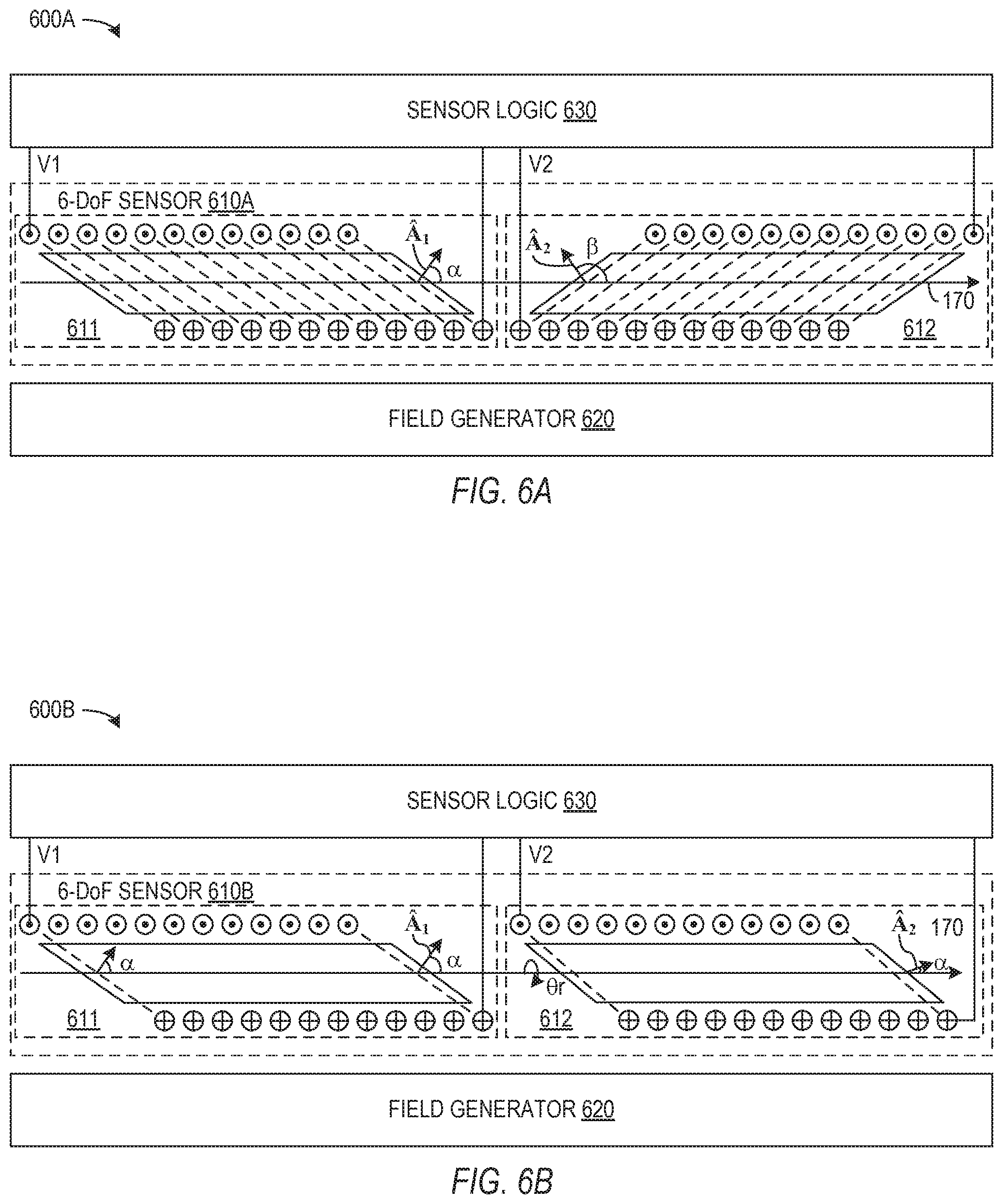
[0034] Off-axis coils can be employed in small diameter 6-DoF sensors that are well adapted for use in minimally invasive medical instruments, e.g., as EM sensor 116 of FIG. 1. FIG. 6A, for example, shows a sensing system 600A employing coils 611 and 612 having lengths aligned along the same axis 170. Each coil 611 and 612 may have a diameter of about 1 mm or less, so that 6-DoF sensor 610A may similarly have a diameter of about 1 mm or less. One or both of coils 611 and 612 can be an off-axis coil such as coil 410, which is described above with reference to FIG. 4. For coil 611, a normal direction A.sub.1 of the effective area for magnetic flux is at an angle .alpha. to axis 170. For coil 612, a normal direction A.sub.2 of the effective area for magnetic flux is at an angle .beta. to axis 170. At least one of coils 611 and 612 are off-axis coils, i.e., .alpha..noteq.0 or .beta..noteq.0, which enables measurement of a roll angle about axis 170.
[0035] EM sensing using a single coil can generally only measure a set of five degrees of freedom because a single-coil EM sensor cannot distinguish rotations about the normal direction associated with the effective area of its coil. Two coils 611 and 612 with different normal directions A.sub.1 and A.sub.2 are used in sensor system 600A, so that each of coils 611 and 612 measures a different set of five degrees of freedom. In particular, a field generator 620 can produce a variable magnetic field that passes through coils 611 and 612. Coils 611 and 612 then produce respective induced voltages V1 and V2, and sensor logic 630 can process signal V1 to determine measurements of one set of five degrees of freedom and process signal V2 to determine measurements of a different set of five degrees of freedom. Sensor logic 630, which may include software for analyzing digitized versions of signals V1 and V2, can account for the difference in position of coils 611 and 612 and generate measurements of six degrees of freedom, e.g., position coordinates X, Y, and Z and pitch, yaw, and roll angles.
[0036] Coils 611 and 612 in the specific configuration illustrated in FIG. 6A are identical off-axis coils, but are oriented so coil 612 is rotated by 180.degree., e.g., about a yaw axis of sensor 610A, relative to coil 611. As a result, angle .beta. of a normal direction A.sub.2 to axis 170 is the supplement to angle .alpha., i.e., .beta.=180.degree.-.alpha.. Sensing system 600A may be able to achieve highest accuracy measurements if normal directions A.sub.1 and A.sub.2 are perpendicular to each other, and in one particular configuration of sensor 610A, angle .alpha. is 45.degree. to make normal directions A.sub.1 and A.sub.2 perpendicular. If coils 611 and 612 are not identical, a wide range of combinations of angles .alpha. and .beta. are possible that make normal directions A.sub.1 and A.sub.2 perpendicular, e.g., configurations where |.beta.-.alpha.|-90.degree..
[0037] FIG. 6B shows another sensing system 600B using a 6-DoF sensor 610B containing two identical off-axis coils 611 and 612. Coils 611 and 612 in FIG. 6B have respective normal directions A.sub.1 and A.sub.2, both of which are at angle .alpha. with roll axis 170. However, coil 612 is rotated by an angle .theta.r about roll axis 170 relative to coil 611. In this configuration, normal directions A.sub.1 and A.sub.2 are at an angle to each other that depends on angles .alpha. and .theta.r. If angle .alpha. is greater than or equal to 45.degree., at least one value for angle .theta.r exists that will make normal directions A.sub.1 and A.sub.2 perpendicular. For example, in one configuration, angle .alpha. is 45.degree., angle .theta.r is 180.degree., and normal directions A.sub.1 and A.sub.2 are perpendicular.
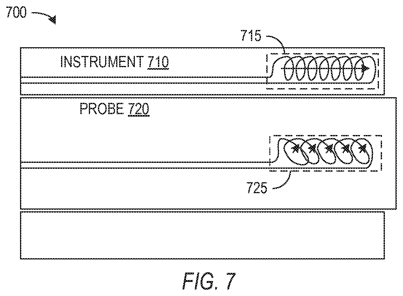
[0038] FIG. 7 shows a medical system 700 capable of measuring six degrees of freedom using a sensing element 715 in an instrument 710 and a coil 725 in a probe 720 that fits within instrument 710. Instrument 710 may be or may include a catheter, a cannula, bronchoscope, endoscope, cannula, or similar instrument through which a probe-like object with unknown roll angle may fit. Sensing element 715 is a device suitable for measurement of at least a pointing direction of the distal tip of instrument 710. As described above, a conventional helical coil can be used to measure five degrees of freedom including a pointing direction of a distal tip of system 700 when such a coil is oriented along a lengthwise axis of system 700, and sensing element 715 could be a coil. Alternatively, sensing element 715 could be another type of sensing device such as a shape sensor, a gravity sensor, a joint angle sensor (for jointed rigid-link instruments), or a vision-based sensor. Note that although described as a system including both a guide instrument 710 and a corresponding probe 720 for exemplary purposes, in various other embodiments, both sensing element 715 and coil 725 can be incorporated into a single instrument.
[0039] Coil 725 is an off-axis coil, which can measure five degrees of freedom and when combined with a measurement of a pointing direction of the roll axis can be used to determine a roll angle as described above. Accordingly, the combination of sensing element 715 in instrument 710 and off-axis coil 725 in probe 725 can provide a 6-DoF measurement of probe 720 including measurement of a roll angle of probe 720. An advantage of system 700 is that the use of a single sensing element 715 in instrument 710 may provide additional space in instrument 710 and probe 720 for other structures, which is particularly important for small diameter devices such as lung catheters. Additionally, in system 700, coil 725, which is in probe 720, may be closer to the center of the distal tip than is sensing element 715, which is in the wall of instrument 710. As a result, the roll axis of coil 725 may closely correspond to the roll axis of system 700 and probe 720. Sensing element 715 in instrument 710 may as indicated above be a conventional helical coil so that a measurement of the direction of the area normal of sensing element 715 indicates the direction of the roll axis, and a measurement of the area normal direction of coil 725 can then give the roll angle of probe 720. Alternatively, sensing element 715 could be an off-axis coil, and if the normal direction of the areas defined by the loops in sensing element 715 differs from the normal direction of the areas defined by the loops in coil 725.
[0040] System 700 may be used by inserting probe 720 through instrument 710 until the distal ends of instrument 710 and probe 720 are aligned. Probe 720 may, for example, be a camera or vision system that is inserted in instrument 710 for navigation of natural lumens such as lung airways. Instrument 710 with the vision probe may then be steered to a worksite where measurements determined using sensing element 715 and coil 725 are used when orienting the distal tip of instrument 700 for a medical function such as biopsying tissue. The vision probe can then be removed and a probe such as a biopsy needle may be inserted in instrument 710 in place of the vision probe. The biopsy probe may similarly contain a coil or EM sensor, but the EM sensor used then may or may not need to be an off-axis coil or a coil intended for use with sensing element 715. For example, a biopsy needle may be inserted past the distal tip of instrument 710, and the position of the tip of the biopsy needle may be important to measure while the roll angle of a symmetric needle does not need to be measured.
[0041] Although the invention has been described with reference to particular embodiments, the description is only an example of the invention's application and should not be taken as a limitation. Various adaptations and combinations of features of the embodiments disclosed are within the scope of the invention as defined by the following claims.
* * * * *
uspto.report is an independent third-party trademark research tool that is not affiliated, endorsed, or sponsored by the United States Patent and Trademark Office (USPTO) or any other governmental organization. The information provided by uspto.report is based on publicly available data at the time of writing and is intended for informational purposes only.
While we strive to provide accurate and up-to-date information, we do not guarantee the accuracy, completeness, reliability, or suitability of the information displayed on this site. The use of this site is at your own risk. Any reliance you place on such information is therefore strictly at your own risk.
All official trademark data, including owner information, should be verified by visiting the official USPTO website at www.uspto.gov. This site is not intended to replace professional legal advice and should not be used as a substitute for consulting with a legal professional who is knowledgeable about trademark law.