Telephoto Lens Assembly And Camera Device
ZHANG; Kaiyuan ; et al.
U.S. patent application number 15/766515 was filed with the patent office on 2020-07-30 for telephoto lens assembly and camera device. The applicant listed for this patent is ZHEJIANG SUNNY OPTICAL CO., LTD. Invention is credited to Fujian DAI, Lin HUANG, Jianke WENREN, Kaiyuan ZHANG.
| Application Number | 20200241247 15/766515 |
| Document ID | 20200241247 / US20200241247 |
| Family ID | 1000004764493 |
| Filed Date | 2020-07-30 |
| Patent Application | download [pdf] |


View All Diagrams
| United States Patent Application | 20200241247 |
| Kind Code | A1 |
| ZHANG; Kaiyuan ; et al. | July 30, 2020 |
TELEPHOTO LENS ASSEMBLY AND CAMERA DEVICE
Abstract
The present application provides a telephoto lens assembly, the telephoto lens assembly includes a first lens, a second lens, a third lens, a fourth lens, and at least one subsequent lens, provided sequentially from an object side to an image side along an optical axis, the first lens has a positive focal power, an object side surface of the first lens is a convex surface, and an axial distance from the object side surface of the first lens to an image plane TTL and a total effective focal length f of the telephoto lens assembly satisfy: TTL/f.ltoreq.1.0, and the fourth lens has a positive focal power, an effective focal length of the first lens f1, an effective focal length of the fourth lens f4 and the total effective focal length f satisfy: 1<|f/f1|+|f/f4|.ltoreq.2.7.
| Inventors: | ZHANG; Kaiyuan; (Ningbo City, CN) ; WENREN; Jianke; (Ningbo City, CN) ; HUANG; Lin; (Ningbo City, CN) ; DAI; Fujian; (Ningbo City, CN) | ||||||||||
| Applicant: |
|
||||||||||
|---|---|---|---|---|---|---|---|---|---|---|---|
| Family ID: | 1000004764493 | ||||||||||
| Appl. No.: | 15/766515 | ||||||||||
| Filed: | May 17, 2017 | ||||||||||
| PCT Filed: | May 17, 2017 | ||||||||||
| PCT NO: | PCT/CN2017/084659 | ||||||||||
| 371 Date: | April 6, 2018 |
| Current U.S. Class: | 1/1 |
| Current CPC Class: | G02B 13/02 20130101; G02B 27/0025 20130101; G02B 9/60 20130101; G02B 13/0045 20130101; H04N 5/2254 20130101 |
| International Class: | G02B 13/00 20060101 G02B013/00; G02B 13/02 20060101 G02B013/02; G02B 9/60 20060101 G02B009/60; G02B 27/00 20060101 G02B027/00; H04N 5/225 20060101 H04N005/225 |
Foreign Application Data
| Date | Code | Application Number |
|---|---|---|
| Jan 4, 2017 | CN | 201710004228.1 |
Claims
1. A telephoto lens assembly, comprising a first lens, a second lens, a third lens, a fourth lens, and at least one subsequent lens, provided sequentially from an object side to an image side along an optical axis, the first lens having a positive focal power, an object side surface of the first lens being a convex surface, and an axial distance from the object side surface of the first lens to an image plane TTL and a total effective focal length f of the telephoto lens assembly satisfying: TTL/f.ltoreq.1.0; and the fourth lens having a positive focal power, an effective focal length of the first lens f1, an effective focal length of the fourth lens f4 and the total effective focal length f satisfying: 1<|f/f1|+|f/f4|.ltoreq.2.7.
2. The telephoto lens assembly according to claim 1, wherein the effective focal length of the first lens f1 and the total effective focal length f satisfy: 0.45<f1/f.ltoreq.1.0.
3. The telephoto lens assembly according to claim 1, wherein the second lens has a negative focal power, an image side surface of the second lens is a concave surface, and an effective focal length of the second lens f2 and the total effective focal length f satisfy: -1.5<f2/f<-0.7.
4. The telephoto lens assembly according to claim 1, wherein an effective focal length of the third lens f3, the effective focal length of the fourth lens f4 and the total effective focal length f satisfy: |f/f3|+|f/f4|<1.5.
5. The telephoto lens assembly according to claim 1, wherein a radius of curvature of an object side surface of the third lens R5 and a radius of curvature of an image side surface of the third lens R6 satisfy: |(R5-R6)/(R5+R6)|.ltoreq.1.
6. The telephoto lens assembly according to claim 1, wherein the at least one subsequent lens comprises a fifth lens, the fifth lens has a negative focal power, and an object side surface of the fifth lens is a concave surface.
7. A telephoto lens assembly, comprising sequentially, from an object side to an image side along an optical axis, a first lens, a second lens, a third lens, and a plurality of subsequent lenses, an axial distance from an object side surface of the first lens to an image plane TTL and a total effective focal length f of the telephoto lens assembly satisfying: TTL/f.ltoreq.1.0, and a radius of curvature of an object side surface of the third lens R5 and a radius of curvature of an image side surface of the third lens R6 satisfying: |(R5-R6)/(R5+R6)|.ltoreq.1.
8. The telephoto lens assembly according to claim 7, wherein the first lens has a positive focal power, the object side surface of the first lens is a convex surface, and an effective focal length of the first lens f1 and the total effective focal length f satisfy: 0.45<f1/f.ltoreq.1.0.
9. The telephoto lens assembly according to claim 7, wherein the second lens has a negative focal power, an image side surface of the second lens is a concave surface, and an effective focal length of the second lens f2 and the total effective focal length f satisfy: -1.5<f2/f<-0.7.
10. The telephoto lens assembly according to claim 7, wherein the plurality of subsequent lenses comprise a fourth lens, the fourth lens has a positive focal power, and an effective focal length of the third lens f3, an effective focal length of the fourth lens f4 and the total effective focal length f satisfy: |f/f3|+|f/f4|<1.5.
11. The telephoto lens assembly according to claim 10, wherein the effective focal length of the first lens f1, the effective focal length of the fourth lens f4 and the total effective focal length f satisfy: 1<|f/f1|+|f/f4|.ltoreq.2.7.
12. The telephoto lens assembly according to claim 10, wherein the plurality of subsequent lenses further comprise a fifth lens, the fifth lens has a negative focal power, and an object side surface of the fifth lens is a concave surface.
13. The telephoto lens assembly according to claim 1, wherein a radius of curvature of an object side surface of the second lens R3 and a radius of curvature of the image side surface of the second lens R4 satisfy: |(R3+R4)/(R3-R4)|.ltoreq.2.
14. The telephoto lens assembly according to claim 1, wherein a radius of curvature of an object side surface of the fourth lens R7 and a radius of curvature of an image side surface of the fourth lens R8 satisfy: |(R7+R8)/(R7-R8)|.ltoreq.2.
15. The telephoto lens assembly according to claim 1, wherein an axial air spacing between the second lens and the third lens T23 and an axial air spacing between the third lens and the fourth lens T34 satisfy: T34/T23<2.5.
16. The telephoto lens assembly according to claim 6, wherein a vector height of the object side surface of the fifth lens at a maximum effective diameter SAG51 and a center thickness of the fifth lens CT5 satisfy: |SAG51/CT5|<4.0.
17. The telephoto lens assembly according to claim 6, wherein an effective focal length of the fifth lens f5 and the total effective focal length f satisfy: -1.5<f5/f<-0.5.
18. The telephoto lens assembly according to claim 6, wherein a center thickness of the first lens CT1, a center thickness of the second lens CT2, a center thickness of the third lens CT3, a center thickness of the fourth lens CT4 and a center thickness of the fifth lens CT5 satisfy: 0.5<(CT2+CT3+CT5)/(CT1+CT4)<1.0.
19. A camera device, comprising the telephoto lens assembly according to claim 1.
20. A camera device, comprising a telephoto lens assembly, the telephoto lens assembly comprising sequentially, from an object side to an image side along an optical axis, a first lens, a second lens, a third lens, and a plurality of subsequent lenses, an axis distance from an object side surface of the first lens to an image plan TTL and a total effective focal length f of the telephoto lens assembly satisfying: TTL/f.ltoreq.1.0, and a radius of curvature of an object side surface of the third lens R5 and a radius of curvature of an image side surface of the third lens R6 satisfying: |(R5-R6)/(R5+R6)|.ltoreq.1.
Description
CROSS-REFERENCE TO RELATED APPLICATIONS
[0001] This application is a U.S. national counterpart application of international application serial No. PCT/CN2017/084659 filed May 17, 2017, which claims priority to Chinese Patent Application No. 201710004228.1, filed Jan. 4, 2017. The disclosures of both PCT/CN2017/084659 and Chinese Patent Application No. 201710004228.1 are hereby incorporated by referenced.
TECHNICAL FIELD
[0002] The present disclosure relates to the field of telephoto lens assembly, and a camera device equipped with the telephoto lens assembly.
BACKGROUND
[0003] As charge-coupled device (CCD) and complementary metal-oxide semiconductor (CMOS) image sensors are having increasingly higher performance and smaller size, telephoto lens assemblies also need to meet the requirements for higher image quality and miniaturization.
[0004] In addition, as one's requirement for the image quality of portable electronic products is getting higher and higher, mobile phones, tablet PCs and other electronic products will become thinner and smaller. To achieve miniaturization, the number of lenses in an imaging lens assembly needs to be reduced as much as possible. However, this may lead to a lack of design freedom, making it difficult to meet the requirements for high imaging performance on the market. Currently, to obtain a broad view image, mainstream telephoto lens assemblies adopt a wide-angle optical system, which, however, is not suitable for photographing a distant object and cannot obtain a clear image.
SUMMARY
[0005] The present application intends to provide a miniaturized telephoto lens assembly having a high resolution.
[0006] According to an aspect, the present application provides a telephoto lens assembly, the telephoto lens assembly includes sequentially, from an object side to an image side along an optical axis: a first lens, a second lens, a third lens, a fourth lens, and at least one subsequent lens, wherein the first lens has a positive focal power, an object side surface of the first lens is a convex surface, and an axial distance from the object side surface of the first lens to an image plane TTL and a total effective focal length f of the telephoto lens assembly may satisfy: TTL/f.ltoreq.1.0, for example, TTL/f.ltoreq.0.99, and the fourth lens has a positive focal power, an effective focal length of the first lens f1, an effective focal length of the fourth lens f4 and the total effective focal length f of the telephoto lens assembly may satisfy: 1<|f/f1|+|f/f4|.ltoreq.2.7, for example, 1.16.ltoreq.|f/f1|+|f/f4|.ltoreq.2.7.
[0007] According to an embodiment of the present application, the effective focal length of the first lens f1 and the total effective focal length f satisfy: 0.45<f1/f.ltoreq.1.0, for example, 0.46.ltoreq.f1/f.ltoreq.1.0.
[0008] According to an embodiment of the present application, the second lens has a negative focal power, and an image side surface of the second lens is a concave surface. An effective focal length of the second lens f2 and the total effective focal length f may satisfy: -1.5<f2/f<-0.7, for example, -1.48.ltoreq.f2/f.ltoreq.-0.77.
[0009] According to an embodiment of the present application, an effective focal length of the third lens f3, the effective focal length of the fourth lens f4 and the total effective focal length f may satisfy: |f/f3|+|f/f4|<1.5, for example, |f/f3|+|f/f4|.ltoreq.1.44.
[0010] According to an embodiment of the present application, a radius of curvature of an object side surface of the fourth lens R7 and a radius of curvature of an image side surface of the fourth lens R8 may satisfy: |(R7+R8)/(R7-R8)|.ltoreq.2, for example, |(R7+R8)/(R7-R8)|.ltoreq.1.92.
[0011] According to an embodiment of the present application, an axial air spacing between the second lens and the third lens T23 and an axial air spacing between the third lens and the fourth lens T34 may satisfy: T34/T23<2.5, for example, T34/T23.ltoreq.2.3.
[0012] According to an embodiment of the present application, a radius of curvature of an object side surface of the second lens R3 and a radius of curvature of the image side surface of the second lens R4 may satisfy: |(R3+R4)/(R3-R4)|.ltoreq.2, for example, |(R3+R4)/(R3-R4)|.ltoreq.1.8.
[0013] According to an embodiment of the present application, a radius of curvature of an object side surface of the third lens R5 and a radius of curvature of an image side surface of the third lens R6 may satisfy: |(R5-R6)/(R5+R6)|.ltoreq.1, for example, |(R5-R6)/(R5+R6)|.ltoreq.0.97.
[0014] According to an embodiment of the present application, the at least one subsequent lens may include a fifth lens having a negative focal power, and an object side surface of the fifth lens is a concave surface. A vector height of the object side surface of the fifth lens at a maximum effective diameter SAG51 and a center thickness of the fifth lens CT5 may satisfy: |SAG51/CT5|<4.0, for example, |SAG51/CT5|.ltoreq.3.56.
[0015] According to an embodiment of the present application, an effective focal length of the fifth lens f5 and the total effective focal length f may satisfy: -1.5<f5/f<-0.5, for example, -1.26f5/f.ltoreq.-0.52.
[0016] According to an embodiment of the present application, a center thickness of the first lens CT1, a center thickness of the second lens CT2, a center thickness of the third lens CT3, a center thickness of the fourth lens CT4 and the center thickness of the fifth lens CT5 may satisfy: 0.5<(CT2+CT3+CT5)/(CT1+CT4)<1.0, for example, 0.56.ltoreq.(CT2+CT3+CT5)/(CT1+CT4).ltoreq.0.95.
[0017] According to another aspect, the present application provides a telephoto lens assembly. The telephoto lens assembly may include sequentially, from an object side to an image side along an optical axis: a first lens, a second lens, a third lens, and a plurality of subsequent lenses, wherein an axial distance from an object side surface of the first lens to an image plane TTL and a total effective focal length f of the telephoto lens assembly may satisfy: TTL/f.ltoreq.1.0, for example, TTL/f.ltoreq.0.99; and a radius of curvature of an object side surface of the third lens R5 and a radius of curvature of an image side surface of the third lens R6 may satisfy: |(R5-R6)/(R5+R6)|.ltoreq.1, for example, |(R5-R6)/(R5+R6)|.ltoreq.0.97.
[0018] According to an embodiment of the present application, the first lens may have a positive focal power, the object side surface of the first lens is a convex surface, an effective focal length of the first lens f1 and the total effective focal length f may satisfy: 0.45<f1/f.ltoreq.1.0, for example, 0.46.ltoreq.f1/f.ltoreq.1.0.
[0019] According to an embodiment of the present application, the second lens has a negative focal power, and an image side surface of the second lens is a concave surface. An effective focal length of the second lens f2 and the total effective focal length f may satisfy: -1.5<f2/f<-0.7, for example, -1.48.ltoreq.f2/f.ltoreq.-0.77.
[0020] According to an embodiment of the present application, a radius of curvature of an object side surface of the second lens R3 and a radius of curvature of the image side surface of the second lens R4 may satisfy: |(R3+R4)/(R3-R4)|.ltoreq.2, for example, |(R3+R4)/(R3-R4)|.ltoreq.1.8.
[0021] According to an embodiment of the present application, an axial air spacing between the second lens and the third lens T23 and an axial air spacing between the third lens and the fourth lens T34 may satisfy: T34/T23<2.5, for example, T34/T23.ltoreq.2.3.
[0022] According to an embodiment of the present application, the plurality of subsequent lenses may include a fourth lens having a positive focal power, wherein an effective focal length of the third lens f3, an effective focal length of the fourth lens f4 and the total effective focal length f may satisfy: |f/f3|+|f/f4|<1.5, for example, |f/f3+f/f4.ltoreq.1.44.
[0023] According to an embodiment of the present application, a radius of curvature of an object side surface of the fourth lens R7 and a radius of curvature of an image side surface of the fourth lens R8 may satisfy: |(R7+R8)/(R7-R8)|.ltoreq.2, for example, |(R7+R8)/(R7-R8)|.ltoreq.1.92.
[0024] According to an embodiment of the present application, the effective focal length of the first lens f1, the effective focal length of the fourth lens f4 and the total effective focal length f satisfy: 1<|f/f1|+|f/f4|.ltoreq.2.7, 1.16<|f/f1|+f/f4.ltoreq.2.7.
[0025] According to an embodiment of the present application, wherein, the plurality of subsequent lenses may further include a fifth lens having a negative focal power, and an object side surface of the fifth lens may be a concave surface. A vector height of the object side surface of the fifth lens at a maximum effective diameter SAG51 and a center thickness of the fifth lens CT5 may satisfy: |SAG51/CT5|<4.0, for example, |SAG51/CT5|.ltoreq.3.56.
[0026] According to an embodiment of the present application, an effective focal length of the fifth lens f5 and the total effective focal length f may satisfy: -1.5<f5/f<-0.5, for example, -1.26.ltoreq.f5/f.ltoreq.-0.52.
[0027] According to an embodiment of the present application, a center thickness of the first lens CT1, a center thickness of the second lens CT2, a center thickness of the third lens CT3, a center thickness of the fourth lens CT4, and the center thickness of the fifth lens CT5 may satisfy: 0.5<(CT2+CT3+CT5)/(CT1+CT4)<1.0, for example, 0.56.ltoreq.(CT2+CT3+CT5)/(CT1+CT4).ltoreq.0.95.
[0028] According to another aspect, the present application further provides a camera device that may be equipped with the telephoto lens assembly.
BRIEF DESCRIPTION OF THE DRAWINGS
[0029] The above and other advantages of embodiments of the present application will become apparent from the following detailed description with reference to the accompanying drawings, which are intended to illustrate the exemplary embodiments of the present application rather than limiting them. In the drawings:
[0030] FIG. 1 is a schematic structural diagram illustrating a telephoto lens assembly according to Embodiment 1 of the present application;
[0031] FIG. 2A illustrates a longitudinal aberration curve of the telephoto lens assembly according to Embodiment 1;
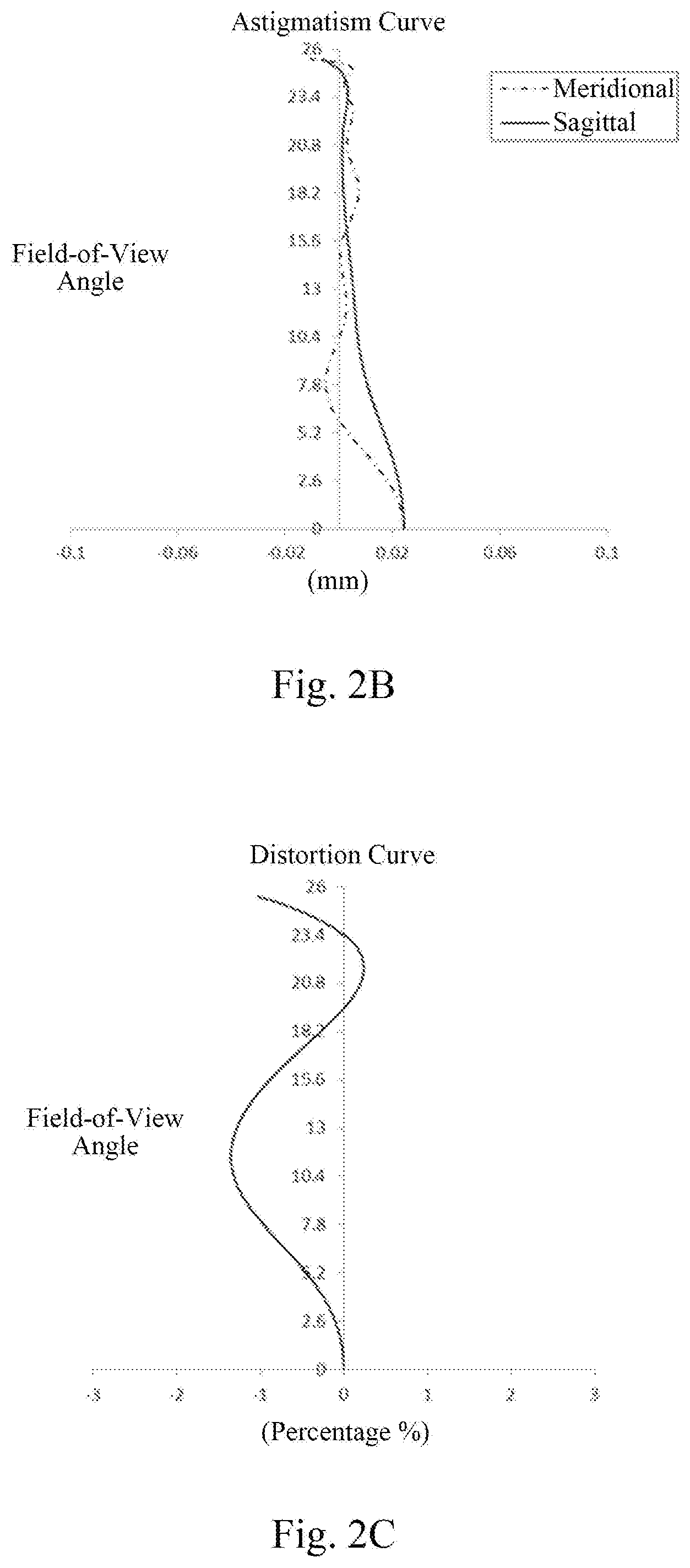
[0032] FIG. 2B illustrates an astigmatism curve of the telephoto lens assembly according to Embodiment 1;
[0033] FIG. 2C illustrates a distortion curve of the telephoto lens assembly according to Embodiment 1;
[0034] FIG. 2D shows a lateral color curve of the telephoto lens assembly according to Embodiment 1;
[0035] FIG. 3 is a schematic structural diagram illustrating a telephoto lens assembly according to Embodiment 2 of the present application;
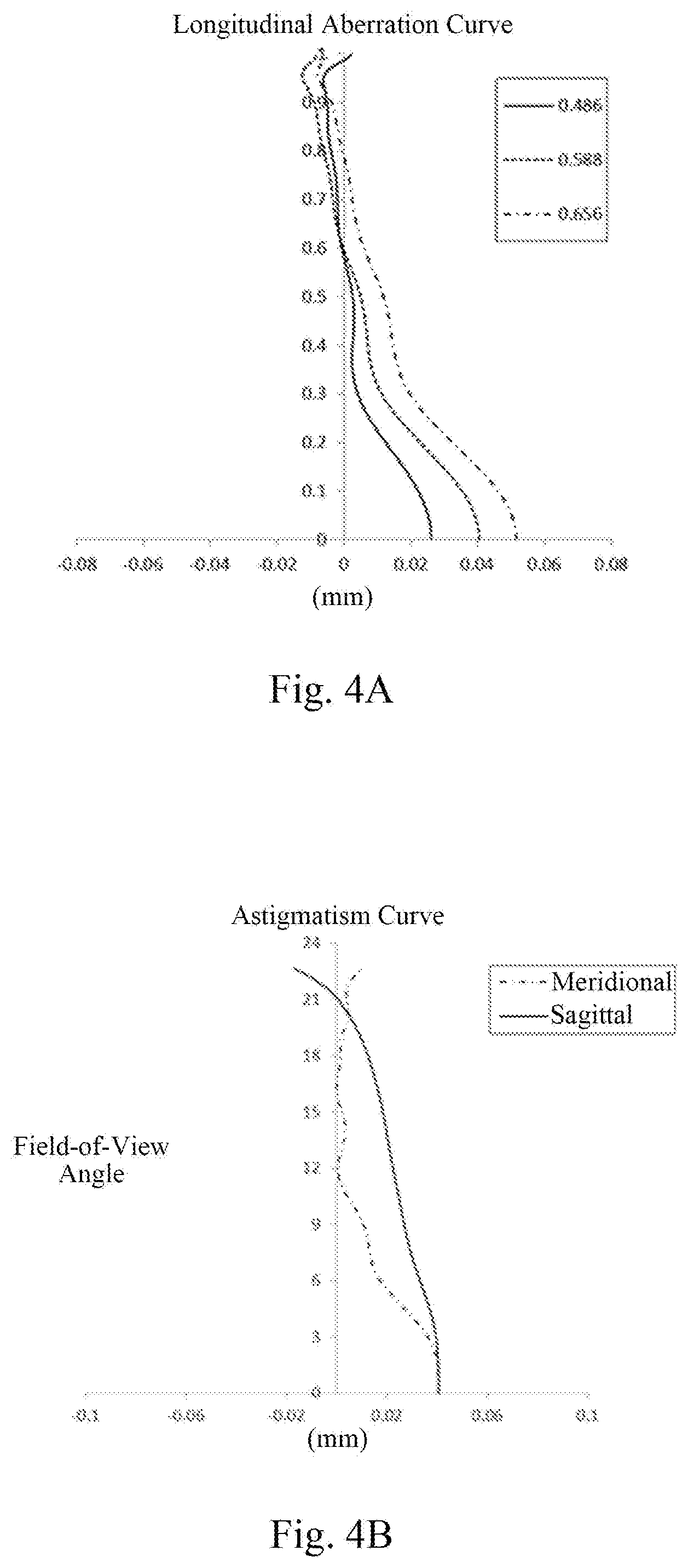
[0036] FIG. 4A illustrates a longitudinal aberration curve of the telephoto lens assembly according to Embodiment 2;
[0037] FIG. 4B illustrates an astigmatism curve of the telephoto lens assembly according to Embodiment 2;
[0038] FIG. 4C illustrates a distortion curve of the telephoto lens assembly according to Embodiment 2;
[0039] FIG. 4D illustrates a lateral color curve of the telephoto lens assembly according to Embodiment 2;
[0040] FIG. 5 is a schematic structural diagram illustrating a telephoto lens assembly according to Embodiment 3 of the present application;
[0041] FIG. 6A illustrates a longitudinal aberration curve of the telephoto lens assembly according to Embodiment 3;
[0042] FIG. 6B illustrates an astigmatism curve of the telephoto lens assembly according to Embodiment 3;
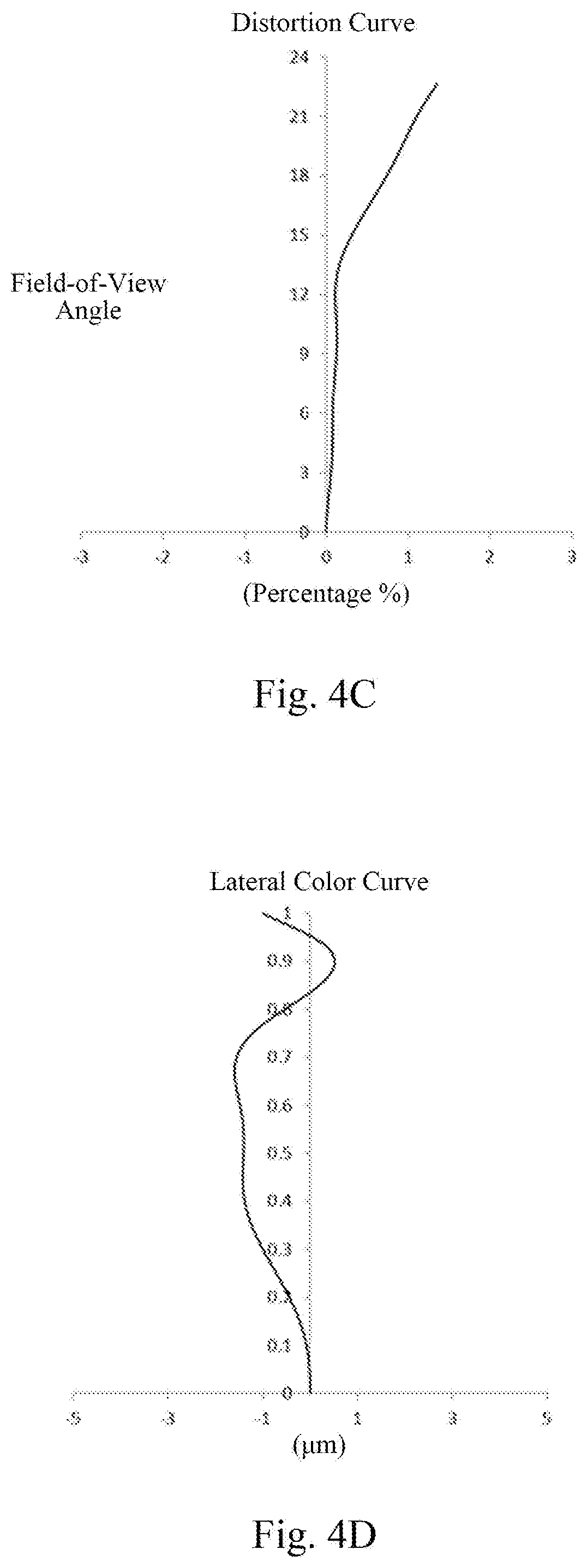
[0043] FIG. 6C illustrates a distortion curve of the telephoto lens assembly according to Embodiment 3;
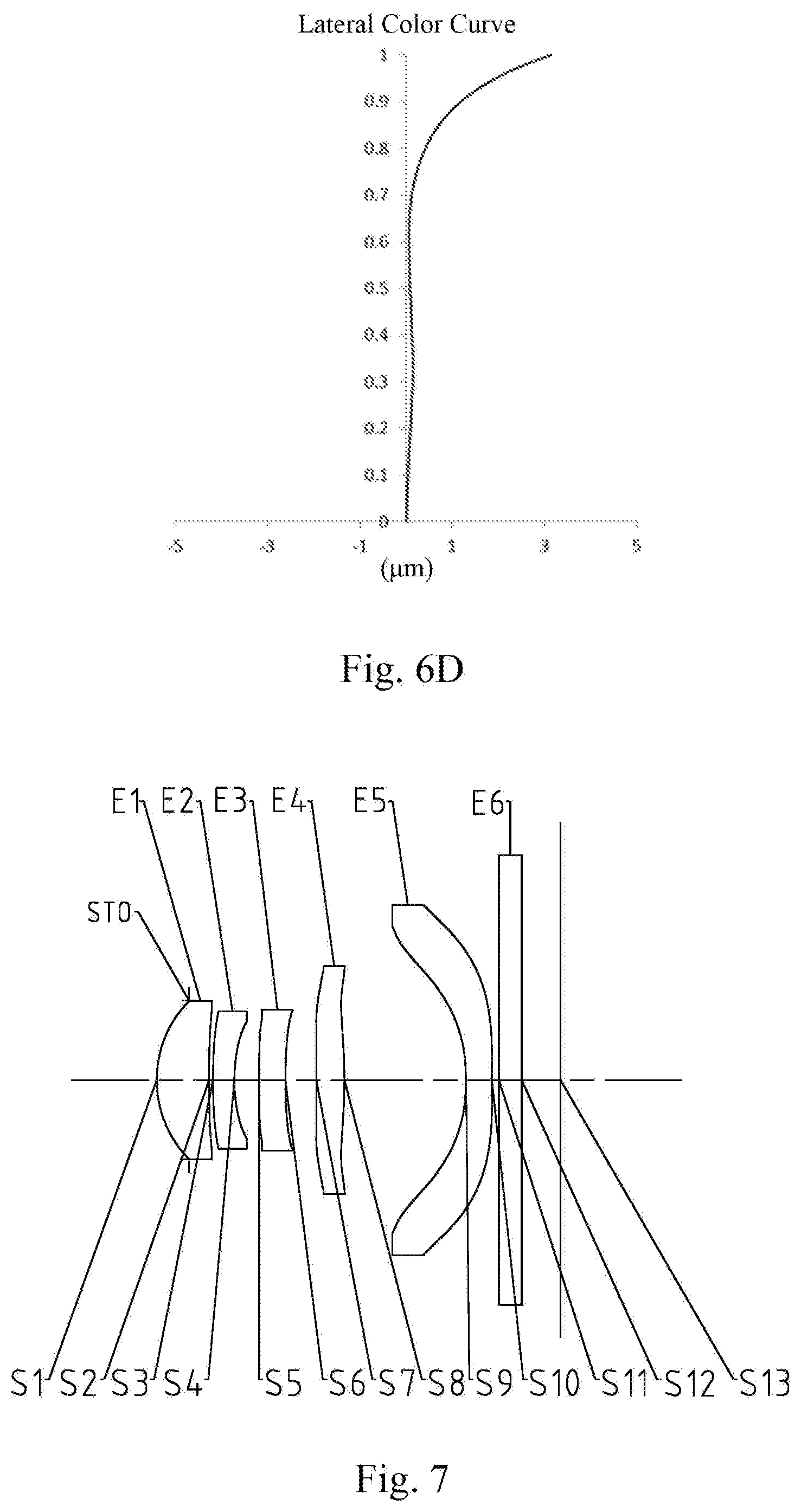
[0044] FIG. 6D illustrates a lateral color curve of the telephoto lens assembly according to Embodiment 3;
[0045] FIG. 7 is a schematic structural diagram illustrating a telephoto lens assembly according to Embodiment 4 of the present application;
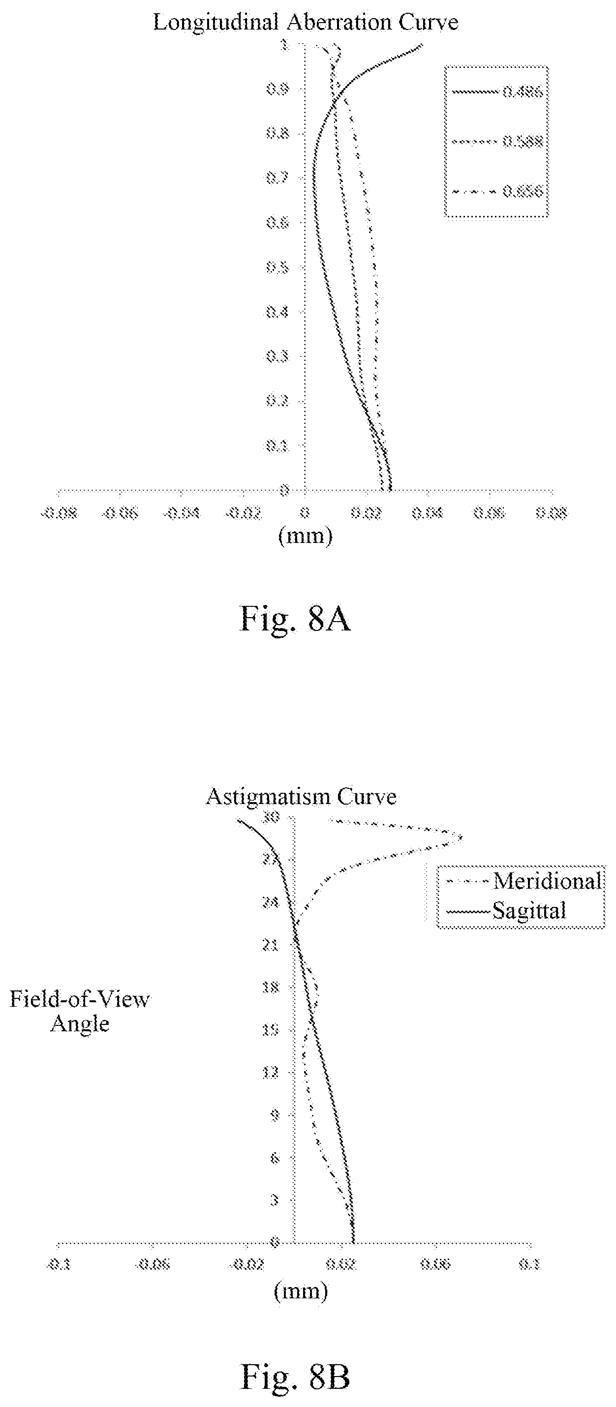
[0046] FIG. 8A illustrates a longitudinal aberration curve of the telephoto lens assembly according to Embodiment 4;
[0047] FIG. 8B illustrates an astigmatism curve of the telephoto lens assembly according to Embodiment 4;
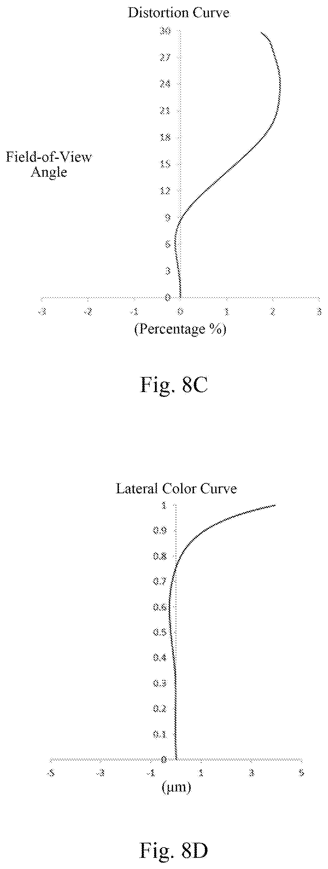
[0048] FIG. 8C illustrates a distortion curve of the telephoto lens assembly according to Embodiment 4;
[0049] FIG. 8D illustrates a lateral color curve of the telephoto lens assembly according to Embodiment 4;
[0050] FIG. 9 is a schematic structural diagram illustrating a telephoto lens assembly according to Embodiment 5 of the present application;
[0051] FIG. 10A illustrates a longitudinal aberration curve of the telephoto lens assembly according to Embodiment 5;
[0052] FIG. 10B illustrates an astigmatism curve of the telephoto lens assembly according to Embodiment 5;
[0053] FIG. 10C illustrates a distortion curve of the telephoto lens assembly according to Embodiment 5;
[0054] FIG. 10D illustrates a lateral color curve of the telephoto lens assembly according to Embodiment 5;
[0055] FIG. 11 is a schematic structural diagram illustrating a telephoto lens assembly according to Embodiment 6 of the present application;
[0056] FIG. 12A illustrates a longitudinal aberration curve of the telephoto lens assembly according to Embodiment 6;
[0057] FIG. 12B illustrates an astigmatism curve of the telephoto lens assembly according to Embodiment 6;
[0058] FIG. 12C illustrates a distortion curve of the telephoto lens assembly according to Embodiment 6;
[0059] FIG. 12D illustrates a lateral color curve of the telephoto lens assembly according to Embodiment 6;
[0060] FIG. 13 is a schematic structural diagram illustrating a telephoto lens assembly according to Embodiment 7 of the present application;
[0061] FIG. 14A illustrates a longitudinal aberration curve of the telephoto lens assembly according to Embodiment 7;
[0062] FIG. 14B illustrates an astigmatism curve of the telephoto lens assembly according to Embodiment 7;
[0063] FIG. 14C illustrates a distortion curve of the telephoto lens assembly according to Embodiment 7;
[0064] FIG. 14D illustrates a lateral color curve of the telephoto lens assembly according to Embodiment 7;
[0065] FIG. 15 is a schematic structural diagram illustrating a telephoto lens assembly according to Embodiment 8 of the present application;
[0066] FIG. 16A illustrates a longitudinal aberration curve of the telephoto lens assembly according to Embodiment 8;
[0067] FIG. 16B illustrates an astigmatism curve of the telephoto lens assembly according to Embodiment 8;
[0068] FIG. 16C illustrates a distortion curve of the telephoto lens assembly according to Embodiment 8;
[0069] FIG. 16D illustrates a lateral color curve of the telephoto lens assembly according to Embodiment 8;
[0070] FIG. 17 is a schematic structural diagram illustrating a telephoto lens assembly according to Embodiment 9 of the present application;
[0071] FIG. 18A illustrates a longitudinal aberration curve of the telephoto lens assembly according to Embodiment 9;
[0072] FIG. 18B illustrates an astigmatism curve of the telephoto lens assembly according to Embodiment 9;
[0073] FIG. 18C illustrates a distortion curve of the telephoto lens assembly according to Embodiment 9;
[0074] FIG. 18D illustrates a lateral color curve of the telephoto lens assembly according to Embodiment 9;
[0075] FIG. 19 is a schematic structural diagram illustrating a telephoto lens assembly according to Embodiment 10 of the present application;
[0076] FIG. 20A illustrates a longitudinal aberration curve of the telephoto lens assembly according to Embodiment 10;
[0077] FIG. 20B illustrates an astigmatism curve of the telephoto lens assembly according to Embodiment 10;
[0078] FIG. 20C illustrates a distortion curve of the telephoto lens assembly according to Embodiment 10;
[0079] FIG. 20D illustrates a lateral color curve of the telephoto lens assembly according to Embodiment 10;
[0080] FIG. 21 is a schematic structural diagram illustrating a telephoto lens assembly according to Embodiment 11 of the present application;
[0081] FIG. 22A illustrates a longitudinal aberration curve of the telephoto lens assembly according to Embodiment 11;
[0082] FIG. 22B illustrates an astigmatism curve of the telephoto lens assembly according to Embodiment 11;
[0083] FIG. 22C illustrates a distortion curve of the telephoto lens assembly according to Embodiment 11;
[0084] FIG. 22D illustrates a lateral color curve of the telephoto lens assembly according to Embodiment 11;
[0085] FIG. 23 is a schematic structural diagram illustrating a telephoto lens assembly according to Embodiment 12 of the present application;
[0086] FIG. 24A illustrates a longitudinal aberration curve of the telephoto lens assembly according to Embodiment 12;
[0087] FIG. 24B illustrates an astigmatism curve of the telephoto lens assembly according to Embodiment 12;
[0088] FIG. 24C illustrates a distortion curve of the telephoto lens assembly according to Embodiment 12; and
[0089] FIG. 24D illustrates a lateral color curve of the telephoto lens assembly according to Embodiment 12.
DETAILED DESCRIPTION OF EMBODIMENTS
[0090] For a better understanding of the present application, various aspects of the present application will be described in more detail with reference to the accompanying drawings. It should be understood that the detailed description is merely illustrative of the exemplary embodiments of the present application and is not intended to limit the scope of the present application in any way. Throughout the specification, the same reference numerals refer to the same elements. The expression "and/or" includes any and all combinations of one or more of the associated listed items.
[0091] It should be noted that in the present specification, the expressions of the first, the second, the third, etc. are used only to distinguish one feature from another, without indicating any limitation to the feature. Thus, the first lens discussed below may also be referred to as the second lens or the third lens without departing from the teachings of the present application.
[0092] In the accompanying drawings, the thickness, size and shape of the lens have been slightly exaggerated for the convenience of explanation, but it should be understood that the sizes of the components are not limited by the accompanying drawings and may be appropriately adjusted within a certain range. In particular, shapes of spherical surfaces or aspheric surfaces shown in the accompanying drawings are shown by way of example. That is, shapes of the spherical surfaces or the aspheric surfaces are not limited to the shapes of the spherical surfaces or the aspheric surfaces shown in the accompanying drawings. The accompanying drawings are merely illustrative and not strictly drawn to scale.
[0093] In addition, the paraxial area refers to an area near the optical axis. The first lens is the lens closest to the object and the sixth lens is the lens closest to the photosensitive element. The surface closest to the object in each lens herein is referred to as the object side surface, and the surface closest to the image plane in each lens is referred to as the image side surface.
[0094] It should be further understood that the terms "comprising," "including," "having" and variants thereof, when used in this specification, specify the presence of stated features, unities, steps, operations, elements and/or components, but do not exclude the presence or addition of one or more other features, unities, steps, operations, elements, components and/or combinations thereof. In addition, expressions, such as "at least one of," when preceding a list of features, modify the entire list of features rather than an individual feature in the list. Further, the use of "may", when describing embodiments of the present application, relates to "one or more embodiments of the present application." Also, the term "exemplary" is intended to refer to an example or illustration.
[0095] Unless otherwise defined, all terms (including technical and scientific terms) used herein have the same meaning as commonly understood by those of ordinary skill in the art to which the present application belongs. It should be further understood that terms, such as those defined in commonly used dictionaries, should be interpreted as having a meaning that is consistent with their meaning in the context of the relevant art and will not be interpreted in an idealized or overly formal sense unless expressly so defined herein.
[0096] The features, principles and other aspects of the present application will be described in detail below.
[0097] The present application provides a telephoto lens assembly. The telephoto lens assembly according to an exemplary embodiment of the present application may comprise a first lens, a second lens, a third lens, a fourth lens, at least one subsequent lens and a photosensitive element provided sequentially from an object side to an image side along an optical axis, and the telephoto lens assembly may have a total effective focal length f.
[0098] In an exemplary embodiment, the first lens may have a positive focal power, and an object side surface of the first lens is a convex surface. An axial distance from the object side surface of the first lens to an image plane TTL and a total effective focal length f of the telephoto lens assembly may satisfy: TTL/f.ltoreq.1.0, and more particularly, satisfy TTL/f.ltoreq.0.99. The fourth lens may have a positive focal power. An effective focal length of the first lens f1, an effective focal length of the fourth lens f4 and the total effective focal length f may satisfy: 1<|f/f1|+|f/f4|.ltoreq.2.7, more particularly, satisfy 1.16.ltoreq.f/f1|+|f/f4|.ltoreq.2.7. By reasonably setting the distance from the object side surface of the first lens to the image plane of the telephoto lens assembly, the lens assembly may be made as thin as possible. In addition, by reasonably selecting the focal length of each lens and appropriately adjusting the total effective focal length of the telephoto lens assembly, the telephoto lens assembly can obtain a preferable flat field condition.
[0099] In an exemplary embodiment, the first lens may be set in order that the effective focal length of the first lens f1 and the total effective focal length f satisfy: 0.45<f1/f.ltoreq.1.0, more particularly, satisfy 0.46.ltoreq.f1/f.ltoreq.1.0, to ensure that the first lens has a proper positive focal power, thereby facilitating the design of subsequent lenses.
[0100] In an exemplary embodiment, the second lens may have a negative focal power, and an image side surface of the second lens may be set as a concave surface. An effective focal length of the second lens f2 and the total effective focal length f of the telephoto lens assembly may satisfy: -1.5<f2/f<-0.7, more particularly, satisfy -1.48.ltoreq.f2/f.ltoreq.-0.77. By reasonably setting the effective focal length of the second lens, it is possible to ensure that the second lens is capable of generating a certain positive spherical aberration to balance a negative spherical aberration of the positive focal power lens; if a ratio between the effective focal length of the second lens f2 and the total effective focal length f of the telephoto lens assembly is less than a lower limit value, the correction ability is insufficient, and if it is larger than an upper limit value, an excessive positive spherical aberration is generated.
[0101] In an exemplary embodiment, an effective focal length of the third lens f3, the effective focal length of the fourth lens f4 and the total effective focal length f may satisfy: |f/f3|+|f/f4|<1.5, more particularly, satisfy |f/f3|+|f/f4|.ltoreq.1.44. By reasonably configuring a relationship between the effective focal length of the third lens f3 and the effective focal length of the fourth lens f4, it is possible to ensure that the system obtains a suitable relative brightness.
[0102] In an exemplary embodiment, a radius of curvature of an object side surface of the fourth lens R7 and a radius of curvature of an image side surface of the fourth lens R8 may satisfy: |(R7+R8)/(R7-R8)|.ltoreq.2, for example, satisfy |(R7+R8)/(R7-R8)|.ltoreq.1.92. By making the difference between the radiuses of curvature of the fourth lens as large as possible, it is ensured that the fourth lens has a strong ability of balancing an aberration.
[0103] In an exemplary embodiment, an axial air spacing between the second lens and the third lens T23 and an axial air spacing between the third lens and the fourth lens T34 may satisfy: T34/T23<2.5, for example, T34/T23.ltoreq.2.3. By reasonably selecting axial positions of the second lens and the third lens, a Petzval field curvature can be well corrected.
[0104] In an exemplary embodiment, a radius of curvature of an object side surface of the second lens R3 and a radius of curvature of the image side surface of the second lens R4 may satisfy: |(R3+R4)/(R3-R4)|.ltoreq.2, for example, |(R3+R4)/(R3-R4)|.ltoreq.1.8. By reasonably allocating the curvature of the second lens, the second lens may have a suitable Seidel aberration coefficient, so that a primary aberration can be well balanced.
[0105] In an exemplary embodiment, a radius of curvature of an object side surface of the third lens R5 and a radius of curvature of an image side surface of the third lens R6 may satisfy: |(R5-R6)/(R5+R6).ltoreq.1, more particularly, for example satisfy |(R5-R6)/(R5+R6).ltoreq.0.97. By reasonably setting the curvature of the third lens, a spherical aberration may be effectively corrected.
[0106] In an exemplary embodiment, at least one subsequent lens of the telephoto lens assembly may include a fifth lens having a negative focal power, and an object side surface of the fifth lens is a concave surface. A vector height of the object side surface of the fifth lens at a maximum effective diameter SAG51 and a center thickness of the fifth lens CT5 may satisfy: |SAG51/CT5|<4.0, more particularly, may satisfy |SAG51/CT5|.ltoreq.3.56.
[0107] In an exemplary embodiment, an effective focal length of the fifth lens f5 and the total effective focal length f of the telephoto lens assembly may satisfy: -1.5<f5/f<-0.5, more particularly, satisfy -1.26.ltoreq.f5/f.ltoreq.-0.52, so that the fifth lens has a proper negative focal power.
[0108] In an exemplary embodiment, a center thickness of the first lens CT1, a center thickness of the second lens CT2, a center thickness of the third lens CT3, a center thickness of the fourth lens CT4 and the center thickness of the fifth lens CT5 may satisfy: 0.5<(CT2+CT3+CT5)/(CT1+CT4)<1.0, more particularly, may satisfy: 0.56.ltoreq.(CT2+CT3+CT5)/(CT1+CT4).ltoreq.0.95. By reasonably selecting the thickness of each lens, it is possible to reasonably correct a fifth-order spherical aberration and a chromatic spherical aberration. If the (CT2+CT3+CT5)/(CT1+CT4) is less than a lower limit value, the fifth-order spherical aberration increases significantly, and if the (CT2+CT3+CT5)/(CT1+CT4) is larger than an upper limit, the chromatic spherical aberration increases significantly.
[0109] The present application further provides another telephoto lens assembly. The telephoto lens assembly may include sequentially, from an object side to an image side along an optical axis, a first lens, a second lens, a third lens and a plurality of subsequent lenses. In the telephoto lens assembly, an axial distance from an object side surface of the first lens to an image plane TTL and a total effective focal length f of the telephoto lens assembly may satisfy: TTL/f.ltoreq.1.0, for example, TTL/f.ltoreq.0.99, and a radius of curvature of an object side surface of the third lens R5 and a radius of curvature of an image side surface of the third lens R6 may satisfy: |(R5-R6)/(R5+R6)|.ltoreq.1, for example, |(R5-R6)/(R5+R6)|.ltoreq.0.97. Such designed telephoto lens assembly may effectively correct a spherical aberration as well as ensuring that the lens assembly is as thin as possible.
[0110] In another exemplary embodiment, the first lens may be set in order that an effective focal length of the first lens f1 and the total effective focal length f satisfy: 0.45<f1/f.ltoreq.1.0, more particularly, satisfy 0.46.ltoreq.f1/f.ltoreq.1.0, to ensure that the first lens has a proper positive focal power, thereby facilitating the design of a subsequent lens.
[0111] In another exemplary embodiment, the second lens may have a negative focal power, and an image side surface of the second lens may be set as a concave surface. An effective focal length of the second lens f2 and the total effective focal length f of the telephoto lens assembly may satisfy: -1.5<f2/f<-0.7, more particularly, satisfy -1.48.ltoreq.f2/f.ltoreq.-0.77. By reasonably setting the effective focal length of the second lens, it is possible to ensure that the second lens is capable of generating a certain positive spherical aberration to balance a negative spherical aberration of the positive focal power lens; if a ratio between the effective focal length of the second lens f2 and the total effective focal length f of the telephoto lens assembly is less than a lower limit value, the correction ability is insufficient, and if it is larger than an upper limit value, an excessive positive spherical aberration is generated.
[0112] In another exemplary embodiment, a radius of curvature of an object side surface of the second lens R3 and a radius of curvature of the image side surface of the second lens R4 may satisfy: |(R3+R4)/(R3-R4)|.ltoreq.2, for example, |(R3+R4)/(R3-R4)|.ltoreq.1.8. By reasonably allocating the curvature of the second lens, the second lens may have a suitable Seidel aberration coefficient, so that a primary aberration can be well balanced.
[0113] In another exemplary embodiment, an axial air spacing between the second lens and the third lens T23 and an axial air spacing between the third lens and the fourth lens T34 may satisfy: T34/T23<2.5, for example, T34/T23.ltoreq.2.3. By reasonably selecting axial positions of the second lens and the third lens, a Petzval field curvature can be well corrected.
[0114] In another exemplary embodiment, the plurality of subsequent lenses in the telephoto lens assembly may further include a fourth lens having a positive focal power. An effective focal length of the third lens f3, an effective focal length of the fourth lens f4 and the total effective focal length f of the telephoto lens assembly may satisfy: |f/f3|+|f/f4|<1.5, more particularly, may satisfy |f/f3|+f/f4.ltoreq.1.44. By reasonably configuring a relationship between the effective focal length of the third lens f3 and the effective focal length of the fourth lens f4, it is possible to ensure that the system obtains a suitable relative brightness.
[0115] In another exemplary embodiment, a radius of curvature of an object side surface of the fourth lens R7 and a radius of curvature of an image side surface of the fourth lens R8 may satisfy: |(R7+R8)/(R7-R8)|.ltoreq.2, for example, satisfy |(R7+R8)/(R7-R8)|.ltoreq.1.92. By making the difference between the radiuses of curvature of the fourth lens as large as possible, it is ensured that the fourth lens has a strong ability of balancing an aberration.
[0116] In another exemplary embodiment, the effective focal length of the first lens f1, the effective focal length of the fourth lens f4 and the total effective focal length f may satisfy: 1<|f/f1|+|f/f4|.ltoreq.2.7, more particularly, satisfy 1.16.ltoreq.f/f1|+|f/f4|.ltoreq.2.7. By reasonably selecting the focal length of each lens and appropriately adjusting the total effective focal length of the telephoto lens assembly, the telephoto lens assembly can obtain a preferable flat field condition.
[0117] In another exemplary embodiment, the plurality of subsequent lenses in the telephoto lens assembly may further include a fifth lens. The fifth lens may have a negative focal power, and an object side surface of the fifth lens may be a concave surface. A vector height of the object side surface of the fifth lens at a maximum effective diameter SAG51 and a center thickness of the fifth lens CT5 may satisfy: |SAG51/CT5|<4.0, more particularly, may satisfy |SAG51/CT5|.ltoreq.3.56.
[0118] In another exemplary embodiment, an effective focal length of the fifth lens f5 and the total effective focal length f of the telephoto lens assembly may satisfy: -1.5<f5/f<-0.5, more particularly, satisfy -1.26.ltoreq.f5/f.ltoreq.-0.52, so that the fifth lens has a proper negative focal power.
[0119] In another exemplary embodiment, a center thickness of the first lens CT1, a center thickness of the second lens CT2, a center thickness of the third lens CT3, a center thickness of the fourth lens CT4 and the center thickness of the fifth lens CT5 may satisfy: 0.5<(CT2+CT3+CT5)/(CT1+CT4)<1.0, more particularly, may satisfy: 0.56.ltoreq. (CT2+CT3+CT5)/(CT1+CT4).ltoreq.0.95. By reasonably selecting the thickness of each lens, it is possible to reasonably correct a fifth-order spherical aberration and a chromatic spherical aberration. If the (CT2+CT3+CT5)/(CT1+CT4) is less than a lower limit value, the fifth-order spherical aberration increases significantly, and if the (CT2+CT3+CT5)/(CT1+CT4) is larger than an upper limit, the chromatic spherical aberration increases significantly.
[0120] The present application further provides a camera device. The camera device may include the telephoto lens assembly described above.
[0121] The telephoto lens assembly according to the exemplary embodiments of the present application may use a plurality of lenses, for example, five as used in the present application, but it should be understood as examples rather than limitations. By reasonably allocating the focal power, center thickness, surface form of each lens, axial spacing between lenses, etc., it is possible to provide a miniaturized telephoto lens assembly having a high resolution. In the embodiments of the present application, at least one of the mirror surfaces of the lenses is an aspheric mirror surface. The feature of the aspheric lens is: from the center of the lens to the periphery, the curvature is continuously changing. Unlike the spherical lens with a certain curvature from the center of the lens to the periphery, the aspheric lens has a better radius of curvature feature, which has an advantage of improving a distorted aberration and improving an astigmatic aberration, capable of making the field of view larger and more realistic. Using the aspheric lens, an aberration at the time of imaging can be eliminated as much as possible, thereby improving an image quality.
[0122] However, it should be understood by those skilled in the art that the various results and advantages described below may be obtained by changing the constituting numbers of the lens assemblies without departing from the technical solution claimed by the present application. For example, although five lenses are described as an example in the description of Embodiment 1, the telephoto lens assembly is not limited to including five lenses. If desired, the telephoto lens assembly may also include other numbers of lenses.
[0123] Specific embodiments of the telephoto lens assembly that may be applied to the above-described embodiments are further described below with reference to FIG. 1 to FIG. 24D.
Embodiment 1
[0124] Embodiment 1 of the telephoto lens assembly according to the embodiments of the present application is described below with reference to FIG. 1 to FIG. 2D.
[0125] As shown in FIG. 1, Embodiment 1 of the telephoto lens assembly includes a first lens E1 having an object side surface S1 and an image side surface S2, a second lens E2 having an object side surface S3 and an image side surface S4, a third lens E3 having an object side surface S5 and an image side surface S6, a fourth lens E4 having an object side surface S7 and an image side surface S8 and a fifth lens E5 having an object side surface S9 and an image side surface S10. In this embodiment, the first lens may have a positive focal power and the object side surface of the first lens may be a convex surface; the second lens may have a negative focal power and the image side surface of the second lens may be a concave surface; the third lens may have a positive focal power or a negative focal power; the fourth lens may have a positive focal power; and the fifth lens may have a negative focal power, and the object side surface of the fifth lens may be a concave surface. The telephoto lens assembly may also include a diaphragm (not shown) and a filter E6 having an object side surface S11 and an image side surface S12 and for filtering out the infrared light. In the telephoto lens assembly of the present embodiment, an aperture STO may also be provided to adjust the amount of light entered. Light from an object passes through the surfaces S1 to S12 sequentially and is finally imaged on the image plane S13.
[0126] Effective focal lengths of the lenses f1 to f5, a total effective focal length f of the telephoto lens assembly, a total length of the camera lens TTL and a half maximum field-of-view angle HFOV of the telephoto lens assembly in Embodiment 1 are shown in Table 1 below.
TABLE-US-00001 TABLE 1 f1 (mm) 3.32 f (mm) 6.41 f2 (mm) -9.47 TTL (mm) 5.90 f3 (mm) -9.68 HFOV (deg) 25.55 f4 (mm) 8.27 f5 (mm) -4.59
[0127] With reference to Table 1, the axial distance from the object side surface of the first lens to the image plane TTL and the total effective focal length f of the telephoto lens assembly satisfy: TTL/f=0.92. An effective focal length of the first lens f1 and the total effective focal length f satisfy: f1/f=0.52. An effective focal length of the second lens f2 and the total effective focal length f satisfy: f2/f=-1.48. The effective focal length of the first lens f1, an effective focal length of the fourth lens f4 and the total effective focal length f satisfy: |f/f1|+|f/f4|=2.7. An effective focal length of the third lens f3, the effective focal length of the fourth lens f4 and the total effective focal length f satisfy: |f/f3+f/f4|=1.44. An effective focal length of the fifth lens f5 and the total effective focal length f satisfy: f5/f=-0.72.
[0128] Table 2 shows a surface form, a radius of curvature, a thickness, a material and a conic constant of each lens in this embodiment.
TABLE-US-00002 TABLE 2 surface surface radius of conic number form curvature thickness material constant OBJ spherical infinite infinite STO spherical infinite -0.3858 S1 aspheric 1.8104 0.6977 1.53, 55.8 0.7841 S2 aspheric -77.1829 0.1488 -99.0000 S3 aspheric -9.4854 0.2300 1.64, 23.5 66.3362 S4 aspheric 16.9293 1.3781 -99.0000 S5 aspheric -4.6533 0.2300 1.64, 23.5 14.3804 S6 aspheric -19.0757 0.5366 6.2204 S7 aspheric -23.7893 0 6513 1.66, 20.4 99.0000 S8 aspheric -4.4938 0.5905 1.5747 S9 aspheric -1.9857 0.3000 1.53, 55.8 -1.5709 S10 aspheric -10.8799 0.2666 -0.8600 S11 spherical infinite 0.2100 1.52, 64.2 S12 spherical infinite 0.6604 S13 spherical infinite
[0129] Table 3 shows high-order coefficients A.sub.4, A.sub.6, A.sub.8, A.sub.10, A.sub.12 and A.sub.14 applicable to each of the aspheric surfaces S1 to S10 of the aspheric lenses in this Embodiment.
TABLE-US-00003 TABLE 3 surface number A.sub.4 A.sub.6 A.sub.8 A.sub.10 A.sub.12 A.sub.14 S1 -1.9341E-02 2.420E-03 -2.4298E-02 3.3539E-02 -2.5486E-0 7.8660E-03 S2 -3.7680E-02 4.2305E-02 -5.9015E-03 -2.2809E-0 2.7934E-02 -9.7003E-03 S3 -7.3914E-02 1.2778E-01 -1.0026E-01 4.5244E-02 -7.4047E-03 -2.2859E-03 S4 -4.9649E-02 9.1512E-02 -9.7260E-02 6.1266E-02 -2.5624E-02 3.9480E-03 S5 -7.5395E-02 -1.6644E-01 5.2182E-01 -5.4835E-01 2.7217E-01 -6.0317E-02 S6 -7.7281E-02 -1.0366E-01 3.1184E-01 -2.3485E-01 7.4673E-02 -8.8626E-03 S7 -9.6674E-03 -1.0126E-01 7.1105E-02 -2.2090E-02 3.8613E-03 -3.2075E-04 S8 2.9258E-02 -7.1590E-02 3.4812E-02 -8.9265E-03 8.5341E-04 5.4549E-05 S9 -6.5675E-02 7.8139E-02 -3.7326E-02 9.0424E-03 -1.0574E-03 4.7852E-05 S10 -1.1273E-01 8.2612E-02 -3.0676E-02 6.2815E-03 -7.0086E-04 3.3228E-05
[0130] With reference to Table 2 and Table 3, a center thickness of the first lens CT1, a center thickness of the second lens CT2, a center thickness of the third lens CT3, a center thickness of the fourth lens CT4 and a center thickness of the fifth lens CT5 satisfy: (CT2+CT3+CT5)/(CT1+CT4)=0.56. A radius of curvature of the object side surface of the second lens R3 and a radius of curvature of the image side surface of the second lens R4 satisfy: |(R3+R4)/(R3-R4)|=0.28. An axial air spacing between the second lens and the third lens T23 and n axial air spacing between the third lens and the fourth lens T34 satisfy: T34/T23=0.39. A radius of curvature of the object side surface of the third lens R5 and a radius of curvature of the image side surface of the third lens R6 satisfy: |(R5-R6)/(R5+R6)|=0.61. A radius of curvature of the object side surface of the fourth lens R7 and a radius of curvature of the image side surface of the fourth lens R8 satisfy: |(R7+R8)/(R7-R8)|=1.47.
[0131] In this embodiment, a vector height of the object side surface of the fifth lens at a maximum effective diameter SAG51 and the center thickness of the fifth lens CT5 satisfy: |SAG51/CT5|=2.72.
[0132] FIG. 2A illustrates a longitudinal aberration curve of the telephoto lens assembly according to Embodiment 1, representing deviations of focal points of light of different wavelengths converged after passing through an optical system. FIG. 2B illustrates an astigmatism curve of the telephoto lens assembly according to Embodiment 1, representing a curvature of a meridional image plane and a curvature of a sagittal image plane. FIG. 2C illustrates a distortion curve of the telephoto lens assembly according to Embodiment 1, representing amounts of distortion at different viewing angles. FIG. 2D illustrates a lateral color curve of the telephoto lens assembly according to Embodiment 1, representing deviations of different image heights on an image plane after light passes through the telephoto lens assembly. It can be seen from FIG. 2A to FIG. 2D that the telephoto lens assembly according to Embodiment 1 achieves good image quality while ensuring miniaturization.
Embodiment 2
[0133] A telephoto lens assembly according to Embodiment 2 of the present application is described below with reference to FIG. 3 to FIG. 4D. In addition to parameters of each lens of the telephoto lens assembly, for example, in addition to the radius of curvature, thickness, material, conic constant, effective focal length, axial spacing, higher-order coefficient etc. of each lens, the telephoto lens assembly described in the present Embodiment 2 and the following embodiments is the same as the configuration and construction of the telephoto lens assembly described in Embodiment 1. For the purpose of brevity, the description of parts similar to those in Embodiment 1 will be omitted.
[0134] FIG. 3 is a schematic structural diagram illustrating a telephoto lens assembly according to Embodiment 2 of the present application. As shown in FIG. 3, the telephoto lens assembly according to Embodiment 2 includes five lenses E1-E5 respectively having an object side surface and an image side surface.
[0135] Effective focal lengths of the lenses f1 to f5, a total effective focal length f of the telephoto lens assembly, a total length of the camera lens TTL and a half maximum field-of-view angle HFOV of the telephoto lens assembly in Embodiment 2 are shown in Table 4 below.
TABLE-US-00004 TABLE 4 f1 (mm) 3.06 f (mm) 6.51 f2 (mm) -7.31 TTL (mm) 5.85 f3 (mm) -11.41 HFOV (deg) 22.66 f4 (mm) 11.77 f5 (mm) -5.33
[0136] With reference to Table 4, the axial distance from the object side surface of the first lens to the image plane TTL and the total effective focal length f of the telephoto lens assembly satisfy: TTL/f=0.90. An effective focal length of the first lens f1 and the total effective focal length f satisfy: f1/f=0.47. An effective focal length of the second lens f2 and the total effective focal length f satisfy: f2/f=-1.12. The effective focal length of the first lens f1, an effective focal length of the fourth lens f4 and the total effective focal length f satisfy: |f/f1|+|f/f4|=2.68. An effective focal length of the third lens f3, the effective focal length of the fourth lens f4 and the total effective focal length f satisfy: |f/f3+|f/f4|=1.12. An effective focal length of the fifth lens f5 and the total effective focal length f satisfy: f5/f=-0.82.
[0137] Table 5 shows a surface form, a radius of curvature, a thickness, a material and a conic constant of each lens in this embodiment.
TABLE-US-00005 TABLE 5 surface surface radius of conic number form curvature thickness material constant OBJ spherical infinite infinite STO spherical infinite -0.4254 S1 aspheric 1.7226 0.7466 1.54, 56.1 -0.6443 S2 aspheric -42.7739 0.0500 99.0000 S3 aspheric 20.4577 0.2500 1.66, 20.4 98.3361 S4 aspheric 3.8901 1.0166 7.0669 S5 aspheric -5.4086 0.3140 1.54, 56.1 -99.0000 S6 aspheric -42.8279 1.0307 99.0000 S7 aspheric -17.1098 0.4557 1.66, 20.4 99.0000 S8 aspheric -5.4042 0.2784 4.7305 S9 aspheric -5.3007 0.3500 1.53, 55.8 3.8949 S10 aspheric 6.3052 0.5412 -40.5088 S11 spherical infinite 0.2100 1.52, 64.2 S12 spherical infinite 0.6077 S13 spherical infinite
[0138] Table 6 shows high-order coefficients A.sub.4, A.sub.6, A.sub.8, A.sub.10, A.sub.12, A.sub.14, A.sub.16, A.sub.18 and A.sub.20 applicable to each of the aspheric surfaces S1 to S10 of the aspheric lenses in this Embodiment.
TABLE-US-00006 TABLE 6 surface number A.sub.4 A.sub.6 A.sub.8 A.sub.10 A.sub.12 S1 1.5123E-02 1.0671E-02 -6.0862E-02 2.2823E-01 -4.8494E-01 S2 -8.0524E-02 3.9748E-01 -1.1716E+00 2.2787E+00 -2.9338E+00 S3 -1.0074E-01 4.7025E-01 -1.3118E+00 2.4867E+00 -3.0011E+00 S4 -4.2868E-02 2.0845E-01 -5.4534E-01 9.3043E-01 -6.1725E-01 S5 -6.1119E-02 1.2634E-01 -1.1985E-01 2.6612E-01 -7.1432E-01 S6 3.3176E-02 6.0064E-02 -4.0818E-02 1.2912E-01 -2.6861E-01 S7 1.4892E-02 -1.5488E-01 2.0966E-01 -1.7271E-01 7.9839E-02 S8 1.2805E-01 -3.3749E-01 3.5972E-01 -2.1460E-01 7.6222E-02 S9 5.4904E-02 -2.3597E-01 8.2637E-02 2.0621E-01 -2.5331E-01 S10 -7.4713E-02 -2.4089E-02 1.5224E-02 2.4849E-02 -2.7818E-02 surface number A.sub.14 A.sub.16 A.sub.18 A.sub.20 S1 6.0456E-01 -4.4196E-01 1.7560E-01 -2.9546E-02 S2 2.5035E+00 -1.3877E+00 4.5688E-01 -6.8254E-02 S3 2.2657E+00 -1.0359E+00 2.6145E-01 -2.8122E-02 S4 -4.9881E-01 1.1979E+00 -8.1073E-01 1.9494E-01 S5 1.1770E+00 -1.1398E+00 5.9265E-01 -1.2886E-01 S6 3.3945E-01 -2.6519E-01 1.1228E-01 -1.9437E-02 S7 -1.8356E-02 1.6472E-03 0 0 S8 -2.0248E-02 5.4937E-03 -1.1392E-03 1.0061E-04 S9 1.2825E-01 -3.4033E-02 4.6664E-03 -2.6198E-04 S10 1.2235E-02 -2.8441E-03 3.4761E-04 -1.7659E-05
[0139] With reference to Table 5 and Table 6, a center thickness of the first lens CT1, a center thickness of the second lens CT2, a center thickness of the third lens CT3, a center thickness of the fourth lens CT4 and a center thickness of the fifth lens CT5 satisfy: (CT2+CT3+CT5)/(CT1+CT4)=0.76. A radius of curvature of the object side surface of the second lens R3 and a radius of curvature of the image side surface of the second lens R4 satisfy: |(R3+R4)/(R3-R4)|=1.47. An axial air spacing between the second lens and the third lens T23 and an axial air spacing between the third lens and the fourth lens T34 satisfy: T34/T23=1.01. A radius of curvature of the object side surface of the third lens R5 and a radius of curvature of the image side surface of the third lens R6 satisfy: |(R5-R6)/(R5+R6)|=0.78. A radius of curvature of the object side surface of the fourth lens R7 and a radius of curvature of the image side surface of the fourth lens R8 satisfy: |(R7+R8)/(R7-R8)|=1.92.
[0140] In this embodiment, a vector height of the object side surface of the fifth lens at a maximum effective diameter SAG51 and the center thickness of the fifth lens CT5 satisfy: |SAG51/CT5|=1.55.
[0141] FIG. 4A illustrates a longitudinal aberration curve of the telephoto lens assembly according to Embodiment 2, representing deviations of focal points of light of different wavelengths converged after passing through an optical system. FIG. 4B illustrates an astigmatism curve of the telephoto lens assembly according to Embodiment 2, representing a curvature of a meridional image plane and a curvature of a sagittal image plane. FIG. 4C illustrates a distortion curve of the telephoto lens assembly according to Embodiment 2, representing amounts of distortion at different viewing angles. FIG. 4D illustrates a lateral color curve of the telephoto lens assembly according to Embodiment 2, representing deviations of different image heights on an image plane after light passes through the telephoto lens assembly. It can be seen from FIG. 4A to FIG. 4D that the telephoto lens assembly according to Embodiment 2 achieves good image quality while ensuring miniaturization.
Embodiment 3
[0142] A telephoto lens assembly according to Embodiment 3 of the present application is described below with reference to FIG. 5 to FIG. 6D. FIG. 5 is a schematic structural diagram illustrating a telephoto lens assembly according to Embodiment 3 of the present application. As shown in FIG. 5, the telephoto lens assembly according to Embodiment 3 includes five lenses E1-E5 respectively having an object side surface and an image side surface.
[0143] Effective focal lengths of the lenses f1 to f5, a total effective focal length f of the telephoto lens assembly, a total length of the camera lens TTL and a half maximum field-of-view angle HFOV of the telephoto lens assembly in Embodiment 3 are shown in Table 7 below.
TABLE-US-00007 TABLE 7 f1 (mm) 2.81 f (mm) 5.62 f2 (mm) -4.48 TTL (mm) 5.30 f3 (mm) -38.15 HFOV (deg) 29.77 f4 (mm) 11.74 f5 (mm) -4.58
[0144] With reference to Table 7, the axial distance from the object side surface of the first lens to the image plane TTL and the total effective focal length f of the telephoto lens assembly satisfy: TTL/f=0.94. An effective focal length of the first lens f1 and the total effective focal length f satisfy: f1/f=0.50. An effective focal length of the second lens f2 and the total effective focal length f satisfy: f2/f=-0.80. The effective focal length of the first lens f1, an effective focal length of the fourth lens f4 and the total effective focal length f satisfy: |f/f1|+|f/f4|=2.48. An effective focal length of the third lens f3, the effective focal length of the fourth lens f4 and the total effective focal length f satisfy: |f/f3|+|f/f4|=0.63. An effective focal length of the fifth lens f5 and the total effective focal length f satisfy: f5/f=-0.81.
[0145] Table 8 shows a surface form, a radius of curvature, a thickness, a material and a conic constant of each lens in this embodiment.
TABLE-US-00008 TABLE 8 surface surface radius of conic number form curvature thickness material constant OBJ spherical infinite infinite STO spherical infinite -0.4208 S1 aspheric 1.5347 0.6054 1.53, 55.8 -0.1486 S2 aspheric -58.8128 0.0501 -99.0000 S3 aspheric 8.8948 0.2800 1.66, 20.4 63.4437 S4 aspheric 2.1916 0.3508 3.8358 S5 aspheric 9.7341 0.3252 1.54, 56.1 94.2370 S6 aspheric 6.5484 0.4047 -3.6394 S7 aspheric -266.5953 0.3582 1.66, 20.4 99.0000 S8 aspheric -7.5405 1.7256 -92.9905 S9 aspheric -2.5225 0.3000 1.53, 55.8 0.1466 S10 aspheric 84.0806 0.5141 -18.8463 S11 spherical infinite 0.3000 1.52,64.2 S12 spherical infinite 0.0863 S13 spherical infinite
[0146] Table 9 shows high-order coefficients A.sub.4, A.sub.6, A.sub.8, A.sub.10, A.sub.12, A.sub.14, A.sub.16, A.sub.18 and A.sub.20 applicable to each of the aspheric surfaces S1 to S10 of the aspheric lenses in this Embodiment.
TABLE-US-00009 TABLE 9 surface number A.sub.4 A.sub.6 A.sub.8 A.sub.10 A.sub.12 S1 1.3190E-02 -7.5412E-03 5.2225E-02 -1.2456E-01 1.6414E-01 S2 1.5298E-01 -3.8214E-01 1.0359E+00 -2.4484E+00 4.7340E+00 S3 9.4519E-02 -3.7053E-01 1.3756E+00 -4.1009E+00 9.5271E+00 S4 -5.2094E-02 -1.3741E-03 3.1124E-01 -6.8458E-01 1.5214E+00 S5 -5.7395E-02 5.0858E-02 4.9204E-01 -1.7837E+00 4.4706E+00 S6 -3.2038E-02 1.7541E-01 -4.8132E-01 2.0696E+00 -5.2704E+00 S7 -1.3561E-03 2.7833E-02 -6.7171E-03 8.5930E-03 3.4375E-02 S8 -1.2117E-02 4.6604E-02 -5.2008E-02 7.7468E-02 -6.8457E-02 S9 -1.6890E-01 2.1789E-01 -2.2365E-01 1.5975E-01 -7.5220E-02 S10 -1.9268E-01 2.1627E-01 -1.9276E-01 1.1669E-01 -4.7090E-02 surface number A.sub.14 A.sub.16 A.sub.18 A.sub.20 S1 -7.6157E-02 -5.2646E-02 7.8467E-02 -2.7072E-02 S2 -6.5522E+00 5.8052E+00 -2.9326E+00 6.4036E-01 S3 -1.5297E+01 1.5361E+01 -8.6796E+00 2.1061E+00 S4 -3.1208E+00 4.5441E+00 -4.1044E+00 1.6105E+00 S5 -6.9401E+00 6.0721E+00 -2.6556E+00 4.0423E-01 S6 8.4209E+00 -8.3530E+00 4.6673E+00 -1.1105E+00 S7 -8.9256E-02 7.7599E-02 -3.1316E-02 5.0071E-03 S8 3.8769E-02 -1.5891E-02 3.9570E-03 -4.0079E-04 S9 2.2578E-02 -4.0565E-03 3.9076E-04 -1.5290E-05 S10 1.2416E-02 -2.0513E-03 1.9248E-04 -7.8077E-06
[0147] With reference to Table 8 and Table 9, a center thickness of the first lens CT1, a center thickness of the second lens CT2, a center thickness of the third lens CT3, a center thickness of the fourth lens CT4 and a center thickness of the fifth lens CT5 satisfy: (CT2+CT3+CT5)/(CT1+CT4)=0.94. A radius of curvature of the object side surface of the second lens R3 and a radius of curvature of the image side surface of the second lens R4 satisfy: |(R3+R4)/(R3-R4)|=1.65. An axial air spacing between the second lens and the third lens T23 and an axial air spacing between the third lens and the fourth lens T34 satisfy: T34/T23=1.15. A radius of curvature of the object side surface of the third lens R5 and a radius of curvature of the image side surface of the third lens R6 satisfy: |(R5-R6)/(R5+R6)|=0.20. A radius of curvature of the object side surface of the fourth lens R7 and a radius of curvature of the image side surface of the fourth lens R8 satisfy: |(R7+R8)/(R7-R8)|=1.06.
[0148] In this embodiment, a vector height of the object side surface of the fifth lens at a maximum effective diameter SAG51 and the center thickness of the fifth lens CT5 satisfy: |SAG51/CT5|=3.56.
[0149] FIG. 6A illustrates a longitudinal aberration curve of the telephoto lens assembly according to Embodiment 3, representing deviations of focal points of light of different wavelengths converged after passing through an optical system. FIG. 6B illustrates an astigmatism curve of the telephoto lens assembly according to Embodiment 3, representing a curvature of a meridional image plane and a curvature of a sagittal image plane. FIG. 6C illustrates a distortion curve of the telephoto lens assembly according to Embodiment 3, representing amounts of distortion at different viewing angles. FIG. 6D illustrates a lateral color curve of the telephoto lens assembly according to Embodiment 3, representing deviations of different image heights on an image plane after light passes through the telephoto lens assembly. It can be seen from FIG. 6A to FIG. 6D that the telephoto lens assembly according to Embodiment 3 achieves good image quality while ensuring miniaturization.
Embodiment 4
[0150] A telephoto lens assembly according to Embodiment 4 of the present application is described below with reference to FIG. 7 to FIG. 8D. FIG. 7 is a schematic structural diagram illustrating a telephoto lens assembly according to Embodiment 4 of the present application. As shown in FIG. 7, the telephoto lens assembly according to Embodiment 4 includes five lenses E1-E5 respectively having an object side surface and an image side surface.
[0151] Effective focal lengths of the lenses f1 to f5, a total effective focal length f of the telephoto lens assembly, a total length of the camera lens TTL and a half maximum field-of-view angle HFOV of the telephoto lens assembly in Embodiment 4 are shown in Table 10 below.
TABLE-US-00010 TABLE 10 f1 (mm) 2.78 f (mm) 5.59 f2 (mm) -4.31 TTL (mm) 5.30 f3 (mm) -36.36 HFOV (deg) 29.87 f4 (mm) 11.79 f5 (mm) -4.75
[0152] With reference to Table 10, the axial distance from the object side surface of the first lens to the image plane TTL and the total effective focal length f of the telephoto lens assembly satisfy: TTL/f=0.95. An effective focal length of the first lens f1 and the total effective focal length f satisfy: f1/f=0.50. An effective focal length of the second lens f2 and the total effective focal length f satisfy: f2/f=-0.77. The effective focal length of the first lens f1, an effective focal length of the fourth lens f4 and the total effective focal length f satisfy: |f/f1|+|f/f4|=2.49. An effective focal length of the third lens f3, the effective focal length of the fourth lens f4 and the total effective focal length f satisfy: |f/f3|+|f/f4|=0.63. An effective focal length of the fifth lens f5 and the total effective focal length f satisfy: f5/f=-0.85.
[0153] Table 11 shows a surface form, a radius of curvature, a thickness, a material and a conic constant of each lens in this embodiment.
TABLE-US-00011 TABLE 11 surface surface radius of conic number form curvature thickness material constant OBJ spherical infinite infinite STO spherical infinite -0.4334 S1 aspheric 1.4981 0.6881 1.53, 55.8 -0.1915 S2 aspheric -139.0004 0.0500 99.0000 S3 aspheric 9.7066 0.2800 1.66, 20.4 68.9205 S4 aspheric 2.1780 0.3225 3.9489 S5 aspheric 10.2771 0.3484 1.54, 56.1 52.0915 S6 aspheric 6.6826 0.4053 -17.5999 S7 aspheric -49.1664 0.3693 1.66, 20.4 84.7464 S8 aspheric -6.7436 1.5950 -53.3530 S9 aspheric -3.0846 0.3400 1.53, 55.8 -0.0010 S10 aspheric 14.8079 0.0909 1.8651 S11 spherical infinite 0.3000 1.52, 64.2 S12 spherical infinite 0.5105 S13 spherical infinite
[0154] Table 12 shows high-order coefficients A.sub.4, A.sub.6, A.sub.8, A.sub.10, A.sub.12, A.sub.14, A.sub.16, A.sub.18 and A.sub.20 applicable to each of the aspheric surfaces S1 to S10 of the aspheric lenses in this Embodiment.
TABLE-US-00012 TABLE 12 surface number A.sub.4 A.sub.6 A.sub.8 A.sub.10 A.sub.12 S1 1.4635E-02 -1.1744E-02 8.1307E-02 -2.4197E-01 4.5543E-01 S2 1.7911E-01 -5.6535E-01 1.5973E+00 -3.5918E+00 6.2751E+00 S3 1.3431E-01 -5.8751E-01 1.9775E+00 -5.0882E+00 1.0285E+01 S4 -2.6998E-02 -1.4992E-01 8.7793E-01 -2.5003E+00 5.8216E+00 S5 -4.7594E-02 -1.1130E-02 4.2543E-01 -9.4501E-01 1.1615E+00 S6 -1.2192E-02 1.1403E-01 -4.7586E-01 2.2650E+00 -5.9632E+00 S7 5.4108E-03 3.6344E-02 -1.0320E-01 2.3202E-01 -2.4955E-01 S8 -8.6705E-03 5.4391E-02 -1.1121E-01 1.8213E-01 -1.7434E-01 S9 -1.8849E-01 2.4203E-01 -2.1890E-01 1.2776E-01 -4.9424E-02 S10 -2.1231E-01 2.3891E-01 -1.9781E-01 1.1025E-01 -4.1703E-02 surface number A.sub.14 A.sub.16 A.sub.18 A.sub.20 S1 -5.2270E-01 3.5406E-01 -1.2500E-01 1.5782E-02 S2 -7.9008E+00 6.5136E+00 -3.1270E+00 6.6149E-01 S3 -1.5025E+01 1.4288E+01 -7.8523E+00 1.8897E+00 S4 -9.9119E+00 1.1212E+01 -7.6646E+00 2.3979E+00 S5 7.8297E-01 -4.6625E+00 5.5690E+00 -2.2455E+00 S6 9.7534E+00 -9.9029E+00 5.6649E+00 -1.3820E+00 S7 1.4184E-01 -4.2512E-02 0.005036752 0.000139297 S8 1.0917E-01 -4.5440E-02 1.0974E-02 -1.1215E-03 S9 1.2839E-02 -2.1227E-03 1.9842E-04 -7.9275E-06 S10 1.0504E-02 -1.6789E-03 1.5355E-04 -6.0977E-06
[0155] With reference to Table 11 and Table 12, a center thickness of the first lens CT1, a center thickness of the second lens CT2, a center thickness of the third lens CT3, a center thickness of the fourth lens CT4 and a center thickness of the fifth lens CT5 satisfy: (CT2+CT3+CT5)/(CT1+CT4)=0.92. A radius of curvature of the object side surface of the second lens R3 and a radius of curvature of the image side surface of the second lens R4 satisfy: |(R3+R4)/(R3-R4)|=1.58. An axial air spacing between the second lens and the third lens T23 and an axial air spacing between the third lens and the fourth lens T34 satisfy: T34/T23=1.26. A radius of curvature of the object side surface of the third lens R5 and a radius of curvature of the image side surface of the third lens R6 satisfy: |(R5-R6)/(R5+R6)|=0.21. A radius of curvature of the object side surface of the fourth lens R7 and a radius of curvature of the image side surface of the fourth lens R8 satisfy: |(R7+R8)/(R7-R8)|=1.32.
[0156] In this embodiment, a vector height of the object side surface of the fifth lens at a maximum effective diameter SAG51 and the center thickness of the fifth lens CT5 satisfy: |SAG51/CT5|=2.84.
[0157] FIG. 8A illustrates a longitudinal aberration curve of the telephoto lens assembly according to Embodiment 4, representing deviations of focal points of light of different wavelengths converged after passing through an optical system. FIG. 8B illustrates an astigmatism curve of the telephoto lens assembly according to Embodiment 4, representing a curvature of a meridional image plane and a curvature of a sagittal image plane. FIG. 8C illustrates a distortion curve of the telephoto lens assembly according to Embodiment 4, representing amounts of distortion at different viewing angles. FIG. 8D illustrates a lateral color curve of the telephoto lens assembly according to Embodiment 4, representing deviations of different image heights on an image plane after light passes through the telephoto lens assembly. It can be seen from FIG. 8A to FIG. 8D that the telephoto lens assembly according to Embodiment 4 achieves good image quality while ensuring miniaturization.
Embodiment 5
[0158] A telephoto lens assembly according to Embodiment 5 of the present application is described below with reference to FIG. 9 to FIG. 10D. FIG. 9 is a schematic structural diagram illustrating a telephoto lens assembly according to Embodiment 5 of the present application. As shown in FIG. 9, the telephoto lens assembly according to Embodiment 5 includes five lenses E1-E5 respectively having an object side surface and an image side surface.
[0159] Effective focal lengths of the lenses f1 to f5, a total effective focal length f of the telephoto lens assembly, a total length of the camera lens TTL and a half maximum field-of-view angle HFOV of the telephoto lens assembly in Embodiment 5 are shown in Table 13 below.
TABLE-US-00013 TABLE 13 f1 (mm) 3.44 f (mm) 6.41 f2 (mm) -8.55 TTL (mm) 5.988 f3 (mm) -25.19 HFOV (deg) 24.3 f4 (mm) 8.19 f5 (mm) -3.35
[0160] With reference to Table 13, the axial distance from the object side surface of the first lens to the image plane TTL and the total effective focal length f of the telephoto lens assembly satisfy: TTL/f=0.93. An effective focal length of the first lens f1 and the total effective focal length f satisfy: f1/f=0.54. An effective focal length of the second lens f2 and the total effective focal length f satisfy: f2/f=-1.33. The effective focal length of the first lens f1, an effective focal length of the fourth lens f4 and the total effective focal length f satisfy: |f/f1|+|f/f4|=2.65. An effective focal length of the third lens f3, the effective focal length of the fourth lens f4 and the total effective focal length f satisfy: |f/f3|+|f/f4|=1.04. An effective focal length of the fifth lens f5 and the total effective focal length f satisfy: f5/f=-0.52.
[0161] Table 14 shows a surface form, a radius of curvature, a thickness, a material and a conic constant of each lens in this embodiment.
TABLE-US-00014 TABLE 14 surface surface radius of conic number form curvature thickness material constant OBJ spherical infinite infinite STO spherical infinite -0.3000 S1 aspheric 2.0756 0.6493 1.54, 56.1 0.6639 S2 aspheric -16.9769 0.0717 -21.7573 S3 aspheric -11.8571 0.2500 1.66, 20.4 -99.0000 S4 aspheric 10.8882 1.9530 52.8537 S5 aspheric -7.2168 0.3140 1.54, 56.1 6.8744 S6 aspheric -15.4796 0.4319 48.5372 S7 aspheric 7.6022 0.4247 1.66, 20.4 -56.5712 S8 aspheric -18.3672 0.5255 21.5743 S9 aspheric -1.6129 0.3500 1.53, 55.8 -3.7088 S10 aspheric -17.2863 0.2204 39.3089 S11 spherical infinite 0.2100 1.52, 64.2 S12 spherical infinite 0.5797 S13 spherical infinite
[0162] Table 15 shows high-order coefficients A.sub.4, A.sub.6, A.sub.8, A.sub.10, A.sub.12, A.sub.14, A.sub.16, A.sub.18 and A.sub.20 applicable to each of the aspheric surfaces S1 to S10 of the aspheric lenses in this Embodiment.
TABLE-US-00015 TABLE 15 surface number A.sub.4 A.sub.6 A.sub.8 A.sub.10 A.sub.12 S1 -1.4287E-02 -1.3240E-02 2.9704E-02 -7.4354E-02 1.0265E-01 S2 -3.4586E-02 1.6787E-01 -4.6279E-01 6.8592E-01 -4.8152E-01 S3 -1.7781E-02 2.2527E-01 -7.4222E-01 1.4730E+00 -1.8359E+00 S4 5.9568E-03 1.4562E-01 -6.4369E-01 1.7005E+00 -2.9212E+00 S5 -5.8915E-02 -4.8745E-02 3.2151E-01 -7.7081E-01 1.1167E+00 S6 -9.1014E-02 9.0709E-02 -1.0639E-01 1.5344E-01 -1.2191E-01 S7 4.4840E-02 -1.3823E-01 8.4290E-02 -7.0204E-03 -1.3676E-02 S8 1.4195E-01 -2.5732E-01 1.9844E-01 -9.2144E-02 2.8489E-02 S9 -6.2628E-03 -4.3319E-02 7.9200E-02 -5.1488E-02 1.6731E-02 S10 -1.0301E-01 7.6913E-02 -1.4736E-02 -6.2377E-03 4.2601E-03 surface number A.sub.14 A.sub.16 A.sub.18 A.sub.20 S1 -9.8879E-02 6.3251E-02 -2.4878E-02 4.3250E-03 S2 -8.7247E-02 4.1491E-01 -2.7926E-01 6.4072E-02 S3 1.3655E+00 -5.1156E-01 3.5431E-02 2.2076E-02 S4 3.2668E+00 -2.2911E+00 9.1410E-01 -1.5810E-01 S5 -1.0140E+00 5.5503E-01 -1.6758E-01 2.1425E-02 S6 4.8413E-02 -8.1184E-03 -9.6358E-05 1.3558E-04 S7 7.2489E-03 -1.7195E-03 2.0811E-04 -1.0486E-05 S8 -5.8697E-03 7.6623E-04 -5.6119E-05 1.6685E-06 S9 -2.6345E-03 1.0563E-04 2.0193E-05 -1.9401E-06 S10 -1.1055E-03 1.5453E-04 -1.1480E-05 3.5637E-07
[0163] With reference to Table 14 and Table 15, a center thickness of the first lens CT1, a center thickness of the second lens CT2, a center thickness of the third lens CT3, a center thickness of the fourth lens CT4 and a center thickness of the fifth lens CT5 satisfy: (CT2+CT3+CT5)/(CT1+CT4)=0.85. A radius of curvature of the object side surface of the second lens R3 and a radius of curvature of the image side surface of the second lens R4 satisfy: |(R3+R4)/(R3-R4)|=0.04. An axial air spacing between the second lens and the third lens T23 and an axial air spacing between the third lens and the fourth lens T34 satisfy: T34/T23=0.22. A radius of curvature of the object side surface of the third lens R5 and a radius of curvature of the image side surface of the third lens R6 satisfy: |(R5-R6)/(R5+R6)|=0.36. A radius of curvature of the object side surface of the fourth lens R7 and a radius of curvature of the image side surface of the fourth lens R8 satisfy: |(R7+R8)/(R7-R8)|=0.41.
[0164] In this embodiment, a vector height of the object side surface of the fifth lens at a maximum effective diameter SAG51 and the center thickness of the fifth lens CT5 satisfy: |SAG51/CT5|=1.41.
[0165] FIG. 10A illustrates a longitudinal aberration curve of the telephoto lens assembly according to Embodiment 5, representing deviations of focal points of light of different wavelengths converged after passing through an optical system. FIG. 10B illustrates an astigmatism curve of the telephoto lens assembly according to Embodiment 5, representing a curvature of a meridional image plane and a curvature of a sagittal image plane. FIG. 10C illustrates a distortion curve of the telephoto lens assembly according to Embodiment 5, representing amounts of distortion at different viewing angles. FIG. 10D illustrates a lateral color curve of the telephoto lens assembly according to Embodiment 5, representing deviations of different image heights on an image plane after light passes through the telephoto lens assembly. It can be seen from FIG. 10A to FIG. 10D that the telephoto lens assembly according to Embodiment 5 achieves good image quality while ensuring miniaturization.
Embodiment 6
[0166] A telephoto lens assembly according to Embodiment 6 of the present application is described below with reference to FIG. 11 to FIG. 12D. FIG. 11 is a schematic structural diagram illustrating a telephoto lens assembly according to Embodiment 6 of the present application. As shown in FIG. 11, the telephoto lens assembly according to Embodiment 6 includes five lenses E1-E5 respectively having an object side surface and an image side surface.
[0167] Effective focal lengths of the lenses f1 to f5, a total effective focal length f of the telephoto lens assembly, a total length of the camera lens TTL and a half maximum field-of-view angle HFOV of the telephoto lens assembly in Embodiment 6 are shown in Table 16 below.
TABLE-US-00016 TABLE 16 f1 (mm) 2.99 f (mm) 6.25 f2 (mm) -4.80 TTL (mm) 5.858 f3 (mm) -13.34 HFOV (deg) 22.5 f4 (mm) 10.60 f5 (mm) -5.74
[0168] With reference to Table 16, the axial distance from the object side surface of the first lens to the image plane TTL and the total effective focal length f of the telephoto lens assembly satisfy: TTL/f=0.94. An effective focal length of the first lens f1 and the total effective focal length f satisfy: f1/f=0.48. An effective focal length of the second lens f2 and the total effective focal length f satisfy: f2/f=-0.77. The effective focal length of the first lens f1, an effective focal length of the fourth lens f4 and the total effective focal length f satisfy: |f/f1|+|f/f4|=2.68. An effective focal length of the third lens f3, the effective focal length of the fourth lens f4 and the total effective focal length f satisfy: |f/f3|+|f/f4|=1.06. An effective focal length of the fifth lens f5 and the total effective focal length f satisfy: f5/f=-0.92.
[0169] Table 17 shows a surface form, a radius of curvature, a thickness, a material and a conic constant of each lens in this embodiment.
TABLE-US-00017 TABLE 17 surface surface radius of conic number form curvature thickness material constant OBJ spherical infinite infinite STO spherical infinite -0.3631 S1 aspheric 1.7931 0.6556 1.54, 56.1 -1.1740 S2 aspheric -15.1351 0.3980 1.2071 S3 aspheric -5.3479 0.2500 1.66, 20.4 -25.1690 S4 aspheric 7.9543 1.3682 49.7591 S5 aspheric -2.8995 0.2500 1.54, 56.1 1.9793 S6 aspheric -4.9749 0.2320 -36.3203 S7 aspheric 8.9721 0.4947 1.66, 20.4 12.9660 S8 aspheric -31.2288 1.1317 50.0000 S9 aspheric -2.6142 0.4466 1.53, 55.8 -1.9610 S10 aspheric -18.6384 0.3332 -90.0000 S11 spherical infinite 0.2100 1.52, 64.2 S12 spherical infinite 0.0800 S13 spherical infinite
[0170] Table 18 shows high-order coefficients A.sub.4, A.sub.6, A.sub.8, A.sub.10, A.sub.12, A.sub.14, A.sub.16, A.sub.18 and A.sub.20 applicable to each of the aspheric surfaces S1 to S10 of the aspheric lenses in this Embodiment.
TABLE-US-00018 TABLE 18 surface number A.sub.4 A.sub.6 A.sub.8 A.sub.10 A.sub.12 S1 2.3514E-02 5.7627E-03 -1.4059E-02 3.5504E-02 -4.8318E-02 S2 -3.8251E-04 -1.6315E-04 1.3214E-02 -3.1442E-02 2.8708E-02 S3 -1.3121E-02 4.3221E-02 -1.4804E-02 -9.8421E-02 2.6227E-01 S4 6.8308E-03 2.9450E-02 -1.7466E-02 2.9591E-02 -2.1063E-01 S5 1.5005E-02 -1.7186E-02 -8.0271E-02 4.2765E-01 -7.2747E-01 S6 1.8405E-02 4.7555E-03 -1.1668E-01 4.4268E-01 -6.6418E-01 S7 1.3558E-02 -3.1230E-02 2.8365E-02 -1.1653E-02 5.5458E-05 S8 4.6322E-03 -1.2526E-02 1.9559E-02 -2.3800E-02 1.8476E-02 S9 -4.6784E-03 -1.0080E-02 2.4290E-02 -2.0934E-02 1.0388E-02 S10 -3.4661E-02 -5.7516E-03 1.5810E-02 -1.2372E-02 5.2294E-03 surface number A.sub.14 A.sub.16 A.sub.18 A.sub.20 S1 3.2164E-02 -6.5424E-03 -3.2528E-03 1.1676E-03 S2 -1.0479E-02 -8.4858E-04 -2.7094E-04 6.8433E-04 S3 -3.4333E-01 2.6658E-01 -1.1923E-01 2.4728E-02 S4 5.2487E-01 -6.1595E-01 3.5303E-01 -7.9543E-02 S5 5.6970E-01 -1.9548E-01 5.5837E-03 8.8153E-03 S6 5.2683E-01 -2.3633E-01 5.6913E-02 -5.7277E-03 S7 1.8702E-03 -7.2643E-04 1.1553E-04 -6.8005E-06 S8 -8.6660E-03 2.3963E-03 -3.5825E-04 2.2225E-05 S9 -3.1280E-03 5.5993E-04 -5.4497E-05 2.2124E-06 S10 -1.2761E-03 1.7687E-04 -1.2708E-05 3.5899E-07
[0171] With reference to Table 17 and Table 18, a center thickness of the first lens CT1, a center thickness of the second lens CT2, a center thickness of the third lens CT3, a center thickness of the fourth lens CT4 and a center thickness of the fifth lens CT5 satisfy: (CT2+CT3+CT5)/(CT1+CT4)=0.82. A radius of curvature of the object side surface of the second lens R3 and a radius of curvature of the image side surface of the second lens R4 satisfy: |(R3+R4)/(R3-R4)|=0.20. An axial air spacing between the second lens and the third lens T23 and an axial air spacing between the third lens and the fourth lens T34 satisfy: T34/T23=0.17. A radius of curvature of the object side surface of the third lens R5 and a radius of curvature of the image side surface of the third lens R6 satisfy: |(R5-R6)/(R5+R6)|=0.26. A radius of curvature of the object side surface of the fourth lens R7 and a radius of curvature of the image side surface of the fourth lens R8 satisfy: |(R7+R8)/(R7-R8)|=0.55.
[0172] In this embodiment, a vector height of the object side surface of the fifth lens at a maximum effective diameter SAG51 and the center thickness of the fifth lens CT5 satisfy: |SAG51/CT5|=1.40.
[0173] FIG. 12A illustrates a longitudinal aberration curve of the telephoto lens assembly according to Embodiment 6, representing deviations of focal points of light of different wavelengths converged after passing through an optical system. FIG. 12B illustrates an astigmatism curve of the telephoto lens assembly according to Embodiment 6, representing a curvature of a meridional image plane and a curvature of a sagittal image plane. FIG. 12C illustrates a distortion curve of the telephoto lens assembly according to Embodiment 6, representing amounts of distortion at different viewing angles. FIG. 12D illustrates a lateral color curve of the telephoto lens assembly according to Embodiment 6, representing deviations of different image heights on an image plane after light passes through the telephoto lens assembly. It can be seen from FIG. 12A to FIG. 12D that the telephoto lens assembly according to Embodiment 6 achieves good image quality while ensuring miniaturization.
Embodiment 7
[0174] A telephoto lens assembly according to Embodiment 7 of the present application is described below with reference to FIG. 13 to FIG. 14D. FIG. 13 is a schematic structural diagram illustrating a telephoto lens assembly according to Embodiment 7 of the present application. As shown in FIG. 13, the telephoto lens assembly according to Embodiment 7 includes five lenses E1-E5 respectively having an object side surface and an image side surface.
[0175] Effective focal lengths of the lenses f1 to f5, a total effective focal length f of the telephoto lens assembly, a total length of the camera lens TTL and a half maximum field-of-view angle HFOV of the telephoto lens assembly in Embodiment 7 are shown in Table 19 below.
TABLE-US-00019 TABLE 19 f1 (mm) 2.94 f (mm) 5.47 f2 (mm) -5.80 TTL (mm) 5.308 f3 (mm) -21.58 HFOV (deg) 30.4 f4 (mm) 14.04 f5 (mm) -5.26
[0176] With reference to Table 19, the axial distance from the object side surface of the first lens to the image plane TTL and the total effective focal length f of the telephoto lens assembly satisfy: TTL/f=0.97. An effective focal length of the first lens f1 and the total effective focal length f satisfy: f1/f=0.54. An effective focal length of the second lens f2 and the total effective focal length f satisfy: f2/f=-1.06. The effective focal length of the first lens f1, an effective focal length of the fourth lens f4 and the total effective focal length f satisfy: |f/f1|+|f/f4|=2.25. An effective focal length of the third lens f3, the effective focal length of the fourth lens f4 and the total effective focal length f satisfy: |f/f3|+|f/f4|=0.64. An effective focal length of the fifth lens f5 and the total effective focal length f satisfy: f5/f=-0.96.
[0177] Table 20 shows a surface form, a radius of curvature, a thickness, a material and a conic constant of each lens in this embodiment.
TABLE-US-00020 TABLE 20 surface surface radius of conic number form curvature thickness material constant OBJ spherical infinite infinite STO spherical infinite -0.4081 S1 aspheric 1.4419 0.6938 1.54, 56.1 -0.7910 S2 aspheric 12.2102 0.0919 -56.3891 S3 aspheric -118.9937 0.4671 1.66, 20.4 99.0000 S4 aspheric 3.9645 0.3832 14.6316 S5 aspheric -5.3778 0.3000 1.54, 56.1 30.4184 S6 aspheric -10.1188 0.8832 -98.1830 S7 aspheric 8.1052 0.4247 1.66, 20.4 -99.0000 S8 aspheric 62.9589 0.7621 99.0000 S9 aspheric -4.1598 0.3400 1.53, 55.8 1.1238 S10 aspheric 8.9023 0.0946 -87.3681 S11 spherical infinite 0.3000 1.52, 64.2 S12 spherical infinite 0.5594 S13 spherical infinite
[0178] Table 21 shows high-order coefficients A.sub.4, A.sub.6, A.sub.8, A.sub.10, A.sub.12, A.sub.14, A.sub.16, A.sub.18 and A.sub.20 applicable to each of the aspheric surfaces S1 to S10 of the aspheric lenses in this Embodiment.
TABLE-US-00021 TABLE 21 surface number A.sub.4 A.sub.6 A.sub.8 A.sub.10 A.sub.12 S1 3.5667E-02 -7.1267E-03 1.0421E-01 -3.4511E-01 7.2338E-01 S2 -3.9772E-02 6.6538E-02 -1.7119E-01 6.6295E-01 -1.8564E+00 S3 -3.5430E-02 3.6815E-02 2.9831E-01 -1.2797E+00 2.9474E+00 S4 -3.5487E-02 1.9389E-01 -8.2921E-01 3.2275E+00 -7.7418E+00 S5 -1.7290E-01 4.8059E-02 1.3466E-01 -3.9242E-01 9.8162E-01 S6 -1.4636E-01 3.2602E-02 2.5838E-01 -7.8846E-01 1.5223E+00 S7 3.6147E-02 -1.0645E-01 3.6121E-02 2.7554E-02 -4.3868E-02 S8 7.9114E-02 -1.1132E-01 2.1290E-02 2.9184E-02 -2.6901E-02 S9 3.8777E-02 1.4323E-02 -7.1684E-02 4.9947E-02 -1.7242E-02 S10 -3.1262E-02 3.6458E-02 -4.5704E-02 2.2408E-02 -5.7277E-03 surface number A.sub.14 A.sub.16 A.sub.18 A.sub.20 S1 -9.2824E-01 6.9193E-01 -2.6488E-01 3.4269E-02 S2 3.1400E+00 -3.1869E+00 1.7610E+00 -4.0828E-01 S3 -4.2993E+00 3.9065E+00 -2.0440E+00 4.7515E-01 S4 1.1194E+01 -9.2278E+00 3.9217E+00 -6.6290E-01 S5 -1.3361E+00 8.8481E-01 -2.7730E-01 3.3340E-02 S6 -1.7421E+00 1.1529E+00 -4.1262E-01 6.1697E-02 S7 2.6375E-02 -8.1048E-03 1.2426E-03 -7.5190E-05 S8 1.0468E-02 -2.0533E-03 1.8743E-04 -5.5609E-06 S9 3.4976E-03 -4.2236E-04 2.7954E-05 -7.7690E-07 S10 8.3467E-04 -6.9743E-05 3.1176E-06 -5.7920E-08
[0179] With reference to Table 20 and Table 21, a center thickness of the first lens CT1, a center thickness of the second lens CT2, a center thickness of the third lens CT3, a center thickness of the fourth lens CT4 and a center thickness of the fifth lens CT5 satisfy: (CT2+CT3+CT5)/(CT1+CT4)=0.99. A radius of curvature of the object side surface of the second lens R3 and a radius of curvature of the image side surface of the second lens R4 satisfy: |(R3+R4)/(R3-R4)|=0.94. An axial air spacing between the second lens and the third lens T23 and an axial air spacing between the third lens and the fourth lens T34 satisfy: T34/T23=2.30. A radius of curvature of the object side surface of the third lens R5 and a radius of curvature of the image side surface of the third lens R6 satisfy: |(R5-R6)/(R5+R6)|=0.31. A radius of curvature of the object side surface of the fourth lens R7 and a radius of curvature of the image side surface of the fourth lens R8 satisfy: |(R7+R8)/(R7-R8)|=1.30.
[0180] In this embodiment, a vector height of the object side surface of the fifth lens at a maximum effective diameter SAG51 and the center thickness of the fifth lens CT5 satisfy: |SAG51/CT5|=2.36.
[0181] FIG. 14A illustrates a longitudinal aberration curve of the telephoto lens assembly according to Embodiment 7, representing deviations of focal points of light of different wavelengths converged after passing through an optical system. FIG. 14B illustrates an astigmatism curve of the telephoto lens assembly according to Embodiment 7, representing a curvature of a meridional image plane and a curvature of a sagittal image plane. FIG. 14C illustrates a distortion curve of the telephoto lens assembly according to Embodiment 7, representing amounts of distortion at different viewing angles. FIG. 14D illustrates a lateral color curve of the telephoto lens assembly according to Embodiment 7, representing deviations of different image heights on an image plane after light passes through the telephoto lens assembly. It can be seen from FIG. 14A to FIG. 14D that the telephoto lens assembly according to Embodiment 7 achieves good image quality while ensuring miniaturization.
Embodiment 8
[0182] A telephoto lens assembly according to Embodiment 8 of the present application is described below with reference to FIG. 15 to FIG. 16D. FIG. 15 is a schematic structural diagram illustrating a telephoto lens assembly according to Embodiment 8 of the present application. As shown in FIG. 15, the telephoto lens assembly according to Embodiment 8 includes five lenses E1-E5 respectively having an object side surface and an image side surface.
[0183] Effective focal lengths of the lenses f1 to f5, a total effective focal length f of the telephoto lens assembly, a total length of the camera lens TTL and a half maximum field-of-view angle HFOV of the telephoto lens assembly in Embodiment 8 are shown in Table 22 below.
TABLE-US-00022 TABLE 22 f1 (mm) 2.87 f (mm) 5.58 f2 (mm) -4.89 TTL (mm) 5.308 f3 (mm) -15.23 HFOV (deg) 30.0 f4 (mm) 9.56 f5 (mm) -5.20
[0184] With reference to Table 22, the axial distance from the object side surface of the first lens to the image plane TTL and the total effective focal length f of the telephoto lens assembly satisfy: TTL/f=0.95. An effective focal length of the first lens f1 and the total effective focal length f satisfy: f1/f=0.51. An effective focal length of the second lens f2 and the total effective focal length f satisfy: f2/f=-0.88. The effective focal length of the first lens f1, an effective focal length of the fourth lens f4 and the total effective focal length f satisfy: |f/f1|+|f/f4|=2.53. An effective focal length of the third lens f3, the effective focal length of the fourth lens f4 and the total effective focal length f satisfy: |f/f3|+|f/f4|=0.95. An effective focal length of the fifth lens f5 and the total effective focal length f satisfy: f5/f=-0.93.
[0185] Table 23 shows a surface form, a radius of curvature, a thickness, a material and a conic constant of each lens in this embodiment.
TABLE-US-00023 TABLE 23 surface surface radius of conic number form curvature thickness material constant OBJ spherical infinite Infinite STO spherical infinite -0.4412 S1 aspheric 1.4414 0.7093 1.53, 55.8 -0.0920 S2 aspheric 19.5128 0.0500 99.0000 S3 aspheric 7.9558 0.2800 1.66, 20.4 57.4815 S4 aspheric 2.2670 0.2859 2.4224 S5 aspheric -8.1432 0.3001 1.54, 56.1 95.2175 S6 aspheric -474.0306 0.2157 99.0000 S7 aspheric -57.4786 0.3588 1.66, 20.4 -92.1367 S8 aspheric -5.7043 1.6601 -42.0904 S9 aspheric -19.1640 0.3508 1.53, 55.8 -97.6296 S10 aspheric 3.2708 0.2090 -80.4796 S11 spherical infinite 0.3000 1.52, 64.2 S12 spherical infinite 0.5803 S13 spherical infinite
[0186] Table 24 shows high-order coefficients A.sub.4, A.sub.6, A.sub.8, A.sub.10, A.sub.12, A.sub.14, A.sub.16, A.sub.18 and A.sub.20 applicable to each of the aspheric surfaces S1 to S10 of the aspheric lenses in this Embodiment.
TABLE-US-00024 TABLE 24 surface number A.sub.4 A.sub.6 A.sub.8 A.sub.10 A.sub.12 S1 1.0003E-02 -5.0704E-02 2.7629E-01 -8.6660E-01 1.7124E+00 S2 -2.9055E-03 1.5504E-05 4.5049E-08 -7.5311E-10 2.3565E-12 S3 -4.1279E-16 1.1369E-14 -1.3292E-13 8.3192E-13 -3.0014E-12 S4 3.2203E-02 2.2079E-02 1.4962E-01 -9.6688E-01 4.9536E+00 S5 -3.0244E-02 -3.5057E-01 4.2681E+00 -2.5321E+01 9.4802E+01 S6 -9.1115E-02 9.6391E-02 5.6193E-02 -1.9102E-01 1.5654E-01 S7 -2.6323E-02 6.6878E-02 3.6467E-02 -5.9248E-02 1.8145E-02 S8 -1.7696E-02 5.2228E-02 -1.4807E-03 -2.8043E-03 9.2868E-03 S9 -2.4835E-01 2.5881E-01 -2.4785E-01 1.6061E-01 -6.6086E-02 S10 -8.5172E-02 4.1801E-02 -2.5205E-02 1.0347E-02 -2.5809E-03 surface number A.sub.14 A.sub.16 A.sub.18 A.sub.20 S1 -2.1460E+00 1.6504E+00 -7.0994E-01 1.3017E-01 S2 1.3325E-12 -1.3360E-12 7.3521E-13 -1.7156E-13 S3 6.4184E-12 -8.0252E-12 5.4168E-12 -1.5235E-12 S4 -1.5847E+01 3.0896E+01 -3.3089E+01 1.5066E+01 S5 -2.2691E+02 3.3724E+02 -2.8368E+02 1.0360E+02 S6 -6.4123E-02 1.4466E-02 -1.7202E-03 8.4511E-05 S7 3.4955E-03 -3.1447E-03 6.5242E-04 -4.5609E-05 S8 -1.1022E-02 4.0795E-03 -5.3139E-04 1.2636E-05 S9 1.6999E-02 -2.6135E-03 2.1701E-04 -7.4342E-06 S10 3.7540E-04 -3.0270E-05 1.2469E-06 -2.0240E-08
[0187] With reference to Table 23 and Table 24, a center thickness of the first lens CT1, a center thickness of the second lens CT2, a center thickness of the third lens CT3, a center thickness of the fourth lens CT4 and a center thickness of the fifth lens CT5 satisfy: (CT2+CT3+CT5)/(CT1+CT4)=0.87. A radius of curvature of the object side surface of the second lens R3 and a radius of curvature of the image side surface of the second lens R4 satisfy: |(R3+R4)/(R3-R4)|=1.80. An axial air spacing between the second lens and the third lens T23 and an axial air spacing between the third lens and the fourth lens T34 satisfy: T34/T23=0.75. A radius of curvature of the object side surface of the third lens R5 and a radius of curvature of the image side surface of the third lens R6 satisfy: |(R5-R6)/(R5+R6)|=0.97. A radius of curvature of the object side surface of the fourth lens R7 and a radius of curvature of the image side surface of the fourth lens R8 satisfy: |(R7+R8)/(R7-R8)|=1.22.
[0188] In this embodiment, a vector height of the object side surface of the fifth lens at a maximum effective diameter SAG51 and the center thickness of the fifth lens CT5 satisfy: |SAG51/CT5|=2.18.
[0189] FIG. 16A illustrates a longitudinal aberration curve of the telephoto lens assembly according to Embodiment 8, representing deviations of focal points of light of different wavelengths converged after passing through an optical system. FIG. 16B illustrates an astigmatism curve of the telephoto lens assembly according to Embodiment 8, representing a curvature of a meridional image plane and a curvature of a sagittal image plane. FIG. 16C illustrates a distortion curve of the telephoto lens assembly according to Embodiment 8, representing amounts of distortion at different viewing angles. FIG. 16D illustrates a lateral color curve of the telephoto lens assembly according to Embodiment 8, representing deviations of different image heights on an image plane after light passes through the telephoto lens assembly. It can be seen from FIG. 16A to FIG. 16D that the telephoto lens assembly according to Embodiment 8 achieves good image quality while ensuring miniaturization.
Embodiment 9
[0190] A telephoto lens assembly according to Embodiment 9 of the present application is described below with reference to FIG. 17 to FIG. 18D. FIG. 17 is a schematic structural diagram illustrating a telephoto lens assembly according to Embodiment 9 of the present application. As shown in FIG. 17, the telephoto lens assembly according to Embodiment 9 includes five lenses E1-E5 respectively having an object side surface and an image side surface.
[0191] Effective focal lengths of the lenses f1 to f5, a total effective focal length f of the telephoto lens assembly, a total length of the camera lens TTL and a half maximum field-of-view angle HFOV of the telephoto lens assembly in Embodiment 9 are shown in Table 25 below.
TABLE-US-00025 TABLE 25 f1 (mm) 3.02 f (mm) 5.48 f2 (mm) -6.00 TTL (mm) 5.308 f3 (mm) -20.04 HFOV (deg) 30.3 f4 (mm) 9.26 f5 (mm) -4.70
[0192] With reference to Table 25, the axial distance from the object side surface of the first lens to the image plane TTL and the total effective focal length f of the telephoto lens assembly satisfy: TTL/f=0.97. An effective focal length of the first lens f1 and the total effective focal length f satisfy: f1/f=0.55. An effective focal length of the second lens f2 and the total effective focal length f satisfy: f2/f=-1.09. The effective focal length of the first lens f1, an effective focal length of the fourth lens f4 and the total effective focal length f satisfy: |f/f1|+|f/f4|=2.40. An effective focal length of the third lens f3, the effective focal length of the fourth lens f4 and the total effective focal length f satisfy: |f/f3|+|f/f4|=0.87. An effective focal length of the fifth lens f5 and the total effective focal length f satisfy: f5/f=-0.86.
[0193] Table 26 shows a surface form, a radius of curvature, a thickness, a material and a conic constant of each lens in this embodiment.
TABLE-US-00026 TABLE 26 surface surface radius of conic number form curvature thickness material constant OBJ spherical infinite Infinite STO spherical infinite -0.4066 S1 aspheric 1.4425 0.6856 1.54, 56.1 -0.8383 S2 aspheric 9.7319 0.1478 -91.1481 S3 aspheric 74.3832 0.3923 1.66, 20.4 -99.0000 S4 aspheric 3.7537 0.3808 14.4813 S5 aspheric 31.6813 0.3000 1.54, 56.1 99.0000 S6 aspheric 8.0855 0.7581 22.1609 S7 aspheric -66.5794 0.5092 1.66, 20.4 -83.7435 S8 aspheric -5.6190 0.7505 2.9479 S9 aspheric -2.9707 0.3913 1.53, 55.8 -1.7406 S10 aspheric 16.8960 0.6113 -98.8658 S11 spherical infinite 0.3000 1.52, 64.2 S12 spherical infinite 0.0732 S13 spherical infinite
[0194] Table 27 shows high-order coefficients A.sub.4, A.sub.6, A.sub.8, A.sub.10, A.sub.12, A.sub.14, A.sub.16, A.sub.18 and A.sub.20 applicable to each of the aspheric surfaces S1 to S10 of the aspheric lenses in this Embodiment.
TABLE-US-00027 TABLE 27 surface number A.sub.4 A.sub.6 A.sub.8 A.sub.10 A.sub.12 S1 3.7314E-02 -1.8203E-02 1.5212E-01 -4.7778E-01 9.5806E-01 S2 -4.8623E-02 1.2615E-01 -4.8862E-01 1.8898E+00 -4.8763E+00 S3 -8.3231E-02 1.8491E-01 -1.3983E-01 1.0563E-01 -1.6399E-01 S4 -8.8211E-02 3.0073E-01 -8.6038E-01 3.2209E+00 -8.2647E+00 S5 -2.3516E-01 1.0942E-01 1.7400E-01 -4.8054E-01 7.2018E-01 S6 -1.7056E-01 7.6214E-03 4.9682E-01 -1.3551E+00 2.2644E+00 S7 4.4512E-02 -2.4763E-01 3.4808E-01 -3.4832E-01 2.1551E-01 S8 1.2254E-01 -2.2984E-01 2.0950E-01 -1.3498E-01 5.6683E-02 S9 1.7592E-01 -2.4216E-01 1.5954E-01 -6.5938E-02 1.8207E-02 S10 6.4177E-02 -1.0640E-01 5.9649E-02 -2.1391E-02 5.4456E-03 surface number A.sub.14 A.sub.16 A.sub.18 A.sub.20 S1 -1.2037E+00 9.0959E-01 -3.7244E-01 5.9904E-02 S2 7.8694E+00 -7.7513E+00 4.2428E+00 -9.8957E-01 S3 1.5638E-01 -7.4585E-02 1.7455E-02 -1.6176E-03 S4 1.3002E+01 -1.1922E+01 5.7392E+00 -1.1098E+00 S5 -3.0515E-01 -7.6645E-01 9.6365E-01 -3.1033E-01 S6 -2.3261E+00 1.3855E+00 -4.3753E-01 5.6712E-02 S7 -7.5485E-02 1.3483E-02 -8.8092E-04 -1.6593E-05 S8 -1.4625E-02 2.2257E-03 -1.8315E-04 6.2788E-06 S9 -3.3948E-03 4.2040E-04 -3.1876E-05 1.1266E-06 S10 -9.7364E-04 1.1294E-04 -7.4432E-06 2.0866E-07
[0195] With reference to Table 26 and Table 27, a center thickness of the first lens CT1, a center thickness of the second lens CT2, a center thickness of the third lens CT3, a center thickness of the fourth lens CT4 and a center thickness of the fifth lens CT5 satisfy: (CT2+CT3+CT5)/(CT1+CT4)=0.91. A radius of curvature of the object side surface of the second lens R3 and a radius of curvature of the image side surface of the second lens R4 satisfy: |(R3+R4)/(R3-R4)|=1.11. An axial air spacing between the second lens and the third lens T23 and an axial air spacing between the third lens and the fourth lens T34 satisfy: T34/T23=1.99. A radius of curvature of the object side surface of the third lens R5 and a radius of curvature of the image side surface of the third lens R6 satisfy: |(R5-R6)/(R5+R6)|=0.59. A radius of curvature of the object side surface of the fourth lens R7 and a radius of curvature of the image side surface of the fourth lens R8 satisfy: |(R7+R8)/(R7-R8)|=1.18.
[0196] In this embodiment, a vector height of the object side surface of the fifth lens at a maximum effective diameter SAG51 and the center thickness of the fifth lens CT5 satisfy: |SAG51/CT5|=1.95.
[0197] FIG. 18A illustrates a longitudinal aberration curve of the telephoto lens assembly according to Embodiment 9, representing deviations of focal points of light of different wavelengths converged after passing through an optical system. FIG. 18B illustrates an astigmatism curve of the telephoto lens assembly according to Embodiment 9, representing a curvature of a meridional image plane and a curvature of a sagittal image plane. FIG. 18C illustrates a distortion curve of the telephoto lens assembly according to Embodiment 9, representing amounts of distortion at different viewing angles. FIG. 18D illustrates a lateral color curve of the telephoto lens assembly according to Embodiment 9, representing deviations of different image heights on an image plane after light passes through the telephoto lens assembly. It can be seen from FIG. 18A to FIG. 18D that the telephoto lens assembly according to Embodiment 9 achieves good image quality while ensuring miniaturization.
Embodiment 10
[0198] A telephoto lens assembly according to Embodiment 10 of the present application is described below with reference to FIG. 19 to FIG. 20D. FIG. 19 is a schematic structural diagram illustrating a telephoto lens assembly according to Embodiment 10 of the present application. As shown in FIG. 19, the telephoto lens assembly according to Embodiment 10 includes five lenses E1-E5 respectively having an object side surface and an image side surface.
[0199] Effective focal lengths of the lenses f1 to f5, a total effective focal length f of the telephoto lens assembly, a total length of the camera lens TTL and a half maximum field-of-view angle HFOV of the telephoto lens assembly in Embodiment 10 are shown in Table 28 below.
TABLE-US-00028 TABLE 28 f1 (mm) 3.10 f (mm) 5.48 f2 (mm) -6.46 TTL (mm) 5.308 f3 (mm) -28.05 HFOV (deg) 30.5 f4 (mm) 11.30 f5 (mm) -4.78
[0200] With reference to Table 28, the axial distance from the object side surface of the first lens to the image plane TTL and the total effective focal length f of the telephoto lens assembly satisfy: TTL/f=0.97. An effective focal length of the first lens f1 and the total effective focal length f satisfy: f1/f=0.57. An effective focal length of the second lens f2 and the total effective focal length f satisfy: f2/f=-1.18. The effective focal length of the first lens f1, an effective focal length of the fourth lens f4 and the total effective focal length f satisfy: |f/f1|+|f/f4|=2.25. An effective focal length of the third lens f3, the effective focal length of the fourth lens f4 and the total effective focal length f satisfy: |f/f3|+|f/f4|=0.68. An effective focal length of the fifth lens f5 and the total effective focal length f satisfy: f5/f=-0.87.
[0201] Table 29 shows a surface form, a radius of curvature, a thickness, a material and a conic constant of each lens in this embodiment.
TABLE-US-00029 TABLE 29 surface surface radius of conic number form curvature thickness material constant OBJ spherical infinite Infinite STO spherical infinite -0.3820 S1 aspheric 1.5178 0.6638 1.54, 56.1 -0.9216 S2 aspheric 12.8198 0.0979 -73.8492 S3 aspheric 18.8496 0.3366 1.66, 20.4 79.8950 S4 aspheric 3.4550 0.5789 6.5871 S5 aspheric 13.1472 0.3000 1.54, 56.1 99.0000 S6 aspheric 7.0067 0.8516 -5.8177 S7 aspheric 12.8821 0.4882 1.66, 20.4 -31.2384 S8 aspheric -17.5021 0.6774 71.5418 S9 aspheric -2.5435 0.3655 1.53, 55.8 -0.4616 S10 aspheric -524.8782 0.2196 99.0000 S11 spherical infinite 0.3000 1.52, 64.2 S12 spherical infinite 0.4204 S13 spherical infinite
[0202] Table 30 shows high-order coefficients A.sub.4, A.sub.6, A.sub.8, A.sub.10, A.sub.12, A.sub.14, A.sub.16, A.sub.18 and A.sub.20 applicable to each of the aspheric surfaces S1 to S10 of the aspheric lenses in this Embodiment.
TABLE-US-00030 TABLE 30 surface number A.sub.4 A.sub.6 A.sub.8 A.sub.10 A.sub.12 S1 3.4234E-02 -7.5675E-03 7.0352E-02 -1.8378E-01 2.8078E-01 S2 -6.2595E-02 1.4568E-01 -3.0635E-01 9.0612E-01 -2.1126E+00 S3 -8.8106E-02 1.5201E-01 3.3518E-01 -2.2085E+00 6.5782E+00 S4 -6.4876E-02 3.0923E-01 -1.5039E+00 8.0845E+00 -2.8421E+01 S5 -1.9985E-01 5.8095E-02 3.0557E-01 -1.3161E+00 3.4704E+00 S6 -1.6933E-01 1.2908E-01 -1.4209E-01 3.1293E-01 -3.5151E-01 S7 2.9143E-02 -2.4044E-01 3.9894E-01 -5.0268E-01 4.2623E-01 S8 1.0728E-01 -2.6257E-01 3.3966E-01 -3.3784E-01 2.3188E-01 S9 1.2589E-01 -1.9171E-01 1.4337E-01 -5.9315E-02 1.1250E-02 S10 1.6588E-02 -7.6615E-02 5.4990E-02 -2.4025E-02 7.2481E-03 surface number A.sub.14 A.sub.16 A.sub.18 A.sub.20 S1 -2.2909E-01 5.8475E-02 3.9270E-02 -2.4833E-02 S2 3.1754E+00 -2.9842E+00 1.5643E+00 -3.4978E-01 S3 -1.2103E+01 1.3555E+01 -8.4823E+00 2.2696E+00 S4 6.3165E+01 -8.5845E+01 6.5136E+01 -2.1149E+01 S5 -5.6475E+00 5.5799E+00 -3.0810E+00 7.1791E-01 S6 1.6908E-01 4.7863E-02 -9.0517E-02 2.7647E-02 S7 -2.4656E-01 9.4970E-02 -2.1491E-02 2.1083E-03 S8 -1.0601E-01 3.0600E-02 -4.9711E-03 3.4254E-04 S9 3.4272E-04 -5.3090E-04 8.4338E-05 -4.4078E-06 S10 -1.4823E-03 1.8875E-04 -1.3074E-05 3.6655E-07
[0203] With reference to Table 29 and Table 30, a center thickness of the first lens CT1, a center thickness of the second lens CT2, a center thickness of the third lens CT3, a center thickness of the fourth lens CT4 and a center thickness of the fifth lens CT5 satisfy: (CT2+CT3+CT5)/(CT1+CT4)=0.87. A radius of curvature of the object side surface of the second lens R3 and a radius of curvature of the image side surface of the second lens R4 satisfy: |(R3+R4)/(R3-R4)|=1.45. An axial air spacing between the second lens and the third lens T23 and an axial air spacing between the third lens and the fourth lens T34 satisfy: T34/T23=1.47. A radius of curvature of the object side surface of the third lens R5 and a radius of curvature of the image side surface of the third lens R6 satisfy: |(R5-R6)/(R5+R6)|=0.30. A radius of curvature of the object side surface of the fourth lens R7 and a radius of curvature of the image side surface of the fourth lens R8 satisfy: |(R7+R8)/(R7-R8)|=0.15.
[0204] In this embodiment, a vector height of the object side surface of the fifth lens at a maximum effective diameter SAG51 and the center thickness of the fifth lens CT5 satisfy: |SAG51/CT5|=2.29.
[0205] FIG. 20A illustrates a longitudinal aberration curve of the telephoto lens assembly according to Embodiment 10, representing deviations of focal points of light of different wavelengths converged after passing through an optical system. FIG. 20B illustrates an astigmatism curve of the telephoto lens assembly according to Embodiment 10, representing a curvature of a meridional image plane and a curvature of a sagittal image plane. FIG. 20C illustrates a distortion curve of the telephoto lens assembly according to Embodiment 10, representing amounts of distortion at different viewing angles. FIG. 20D illustrates a lateral color curve of the telephoto lens assembly according to Embodiment 10, representing deviations of different image heights on an image plane after light passes through the telephoto lens assembly. It can be seen from FIG. 20A to FIG. 20D that the telephoto lens assembly according to Embodiment 10 achieves good image quality while ensuring miniaturization.
Embodiment 11
[0206] A telephoto lens assembly according to Embodiment 11 of the present application is described below with reference to FIG. 21 to FIG. 22D. FIG. 21 is a schematic structural diagram illustrating a telephoto lens assembly according to Embodiment 11 of the present application. As shown in FIG. 21, the telephoto lens assembly according to Embodiment 11 includes five lenses E1-E5 respectively having an object side surface and an image side surface.
[0207] Effective focal lengths of the lenses f1 to f5, a total effective focal length f of the telephoto lens assembly, a total length of the camera lens TTL and a half maximum field-of-view angle HFOV of the telephoto lens assembly in Embodiment 11 are shown in Table 31 below.
TABLE-US-00031 TABLE 31 f1 (mm) 2.55 f (mm) 5.48 f2 (mm) -4.32 TTL (mm) 5.308 f3 (mm) -12.24 HFOV (deg) 30.5 f4 (mm) 9.78 f5 (mm) -6.89
[0208] With reference to Table 31, the axial distance from the object side surface of the first lens to the image plane TTL and the total effective focal length f of the telephoto lens assembly satisfy: TTL/f=0.97. An effective focal length of the first lens f1 and the total effective focal length f satisfy: f1/f=0.46. An effective focal length of the second lens f2 and the total effective focal length f satisfy: f2/f=-0.79. The effective focal length of the first lens f1, an effective focal length of the fourth lens f4 and the total effective focal length f satisfy: |f/f1|+|f/f4|=2.70. An effective focal length of the third lens f3, the effective focal length of the fourth lens f4 and the total effective focal length f satisfy: |f/f3|+|f/f4|=1.01. An effective focal length of the fifth lens f5 and the total effective focal length f satisfy: f5/f=-1.26.
[0209] Table 32 shows a surface form, a radius of curvature, a thickness, a material and a conic constant of each lens in this embodiment.
TABLE-US-00032 TABLE 32 surface surface radius of conic number form curvature thickness material constant OBJ spherical infinite Infinite STO spherical 1.3845 0.8213 1.54, 56.1 -2.7500 S1 aspheric 1036.3160 0.0500 -55.0000 S2 aspheric 44.0713 0.3000 1.64, 23.5 53.9702 S3 aspheric 2.5950 0.2525 -1.1453 S4 aspheric infinite 0.4549 S5 aspheric -14.8845 0.3588 1.54, 56.1 -30.1256 S6 aspheric 12.1581 0.5789 -3.2981 S7 aspheric 11.8401 0.5509 1.66, 20.4 -50.1928 S8 aspheric -13.9559 0.2897 44.2384 S9 aspheric -2.1574 0.6430 1.53, 55.8 -1.5289 S10 aspheric -5.7488 0.2638 -45.9764 S11 spherical infinite 0.3000 1.52, 64.2 S12 spherical infinite 0.4362 S13 spherical infinite
[0210] Table 33 shows high-order coefficients A.sub.4, A.sub.6, A.sub.8, A.sub.10, A.sub.12, A.sub.14, A.sub.16, A.sub.18 and A.sub.20 applicable to each of the aspheric surfaces S1 to S10 of the aspheric lenses in this Embodiment.
TABLE-US-00033 TABLE 33 surface number A.sub.4 A.sub.6 A.sub.8 A.sub.10 A.sub.12 S1 1.2911E-01 -5.9438E-02 1.6660E-01 -4.1760E-01 7.1328E-01 S2 -5.1185E-02 1.9358E-01 -4.4416E-01 9.9648E-01 -1.9684E+00 S3 -3.0560E-02 2.4078E-01 -4.2070E-01 8.1999E-01 -1.6381E+00 S4 5.0441E-02 4.2170E-01 -3.6559E+00 2.6731E+01 -1.2182E+02 S5 -1.6551E-01 -1.0512E-01 8.9081E-01 -3.1042E+00 6.4687E+00 S6 -1.7268E-01 1.4538E-01 -3.3707E-01 8.2573E-01 -1.3023E+00 S7 -6.8557E-02 -3.7392E-02 -5.7873E-02 2.2563E-01 -3.5860E-01 S8 4.1119E-02 -1.4345E-01 1.0173E-01 -3.1967E-02 -1.3923E-02 S9 1.0157E-01 -1.6071E-01 1.4222E-01 -8.6329E-02 3.6105E-02 S10 -2.7264E-02 -1.4647E-02 1.4419E-02 -5.5324E-03 1.3371E-03 surface number A.sub.14 A.sub.16 A.sub.18 A.sub.20 S1 -7.8836E-01 5.3547E-01 -2.0529E-01 3.3166E-02 S2 2.6896E+00 -2.2755E+00 1.0628E+00 -2.0909E-01 S3 2.4819E+00 -2.2428E+00 1.0271E+00 -1.6712E-01 S4 3.4812E+02 -6.0449E+02 5.8389E+02 -2.4034E+02 S5 -8.3787E+00 6.4704E+00 -2.6131E+00 3.8786E-01 S6 1.3146E+00 -8.2091E-01 2.8891E-01 -4.3804E-02 S7 3.1297E-01 -1.5125E-01 3.7982E-02 -3.8674E-03 S8 1.8192E-02 -7.2042E-03 1.2989E-03 -9.0479E-05 S9 -9.7374E-03 1.5949E-03 -1.4400E-04 5.4986E-06 S10 -2.9248E-04 5.4663E-05 -5.9764E-06 2.5970E-07
[0211] With reference to Table 32 and Table 33, a center thickness of the first lens CT1, a center thickness of the second lens CT2, a center thickness of the third lens CT3, a center thickness of the fourth lens CT4 and a center thickness of the fifth lens CT5 satisfy: (CT2+CT3+CT5)/(CT1+CT4)=0.95. A radius of curvature of the object side surface of the second lens R3 and a radius of curvature of the image side surface of the second lens R4 satisfy: |(R3+R4)/(R3-R4)|=1.13. An axial air spacing between the second lens and the third lens T23 and an axial air spacing between the third lens and the fourth lens T34 satisfy: T34/T23=0.82. A radius of curvature of the object side surface of the third lens R5 and a radius of curvature of the image side surface of the third lens R6 satisfy: |(R5-R6)/(R5+R6)|=0.96. A radius of curvature of the object side surface of the fourth lens R7 and a radius of curvature of the image side surface of the fourth lens R8 satisfy: |(R7+R8)/(R7-R8)|=0.01.
[0212] In this embodiment, a vector height of the object side surface of the fifth lens at a maximum effective diameter SAG51 and the center thickness of the fifth lens CT5 satisfy: |SAG51/CT5|=2.61.
[0213] FIG. 22A illustrates a longitudinal aberration curve of the telephoto lens assembly according to Embodiment 11, representing deviations of focal points of light of different wavelengths converged after passing through an optical system. FIG. 22B illustrates an astigmatism curve of the telephoto lens assembly according to Embodiment 11, representing a curvature of a meridional image plane and a curvature of a sagittal image plane. FIG. 22C illustrates a distortion curve of the telephoto lens assembly according to Embodiment 11, representing amounts of distortion at different viewing angles. FIG. 22D illustrates a lateral color curve of the telephoto lens assembly according to Embodiment 11, representing deviations of different image heights on an image plane after light passes through the telephoto lens assembly. It can be seen from FIG. 22A to FIG. 22D that the telephoto lens assembly according to Embodiment 11 achieves good image quality while ensuring miniaturization.
Embodiment 12
[0214] A telephoto lens assembly according to Embodiment 12 of the present application is described below with reference to FIG. 23 to FIG. 24D. FIG. 23 is a schematic structural diagram illustrating a telephoto lens assembly according to Embodiment 12 of the present application. As shown in FIG. 23, the telephoto lens assembly according to Embodiment 12 includes five lenses E1-E5 respectively having an object side surface and an image side surface.
[0215] Effective focal lengths of the lenses f1 to f5, a total effective focal length f of the telephoto lens assembly, a total length of the camera lens TTL and a half maximum field-of-view angle HFOV of the telephoto lens assembly in Embodiment 12 are shown in Table 34 below.
TABLE-US-00034 TABLE 34 f1 (mm) 5.49 f (mm) 5.50 f2 (mm) -25.72 TTL (mm) 5.418 f3 (mm) 14.07 HFOV (deg) 30.6 f4 (mm) 33.94 f5 (mm) -5.53
[0216] With reference to Table 34, the axial distance from the object side surface of the first lens to the image plane TTL and the total effective focal length f of the telephoto lens assembly satisfy: TTL/f=0.99. An effective focal length of the first lens f1 and the total effective focal length f satisfy: f1/f=1.00. The effective focal length of the first lens f1, an effective focal length of the fourth lens f4 and the total effective focal length f satisfy: |f/f1|+|f/f4|=1.16. An effective focal length of the third lens f3, the effective focal length of the fourth lens f4 and the total effective focal length f satisfy: |f/f3|+|f/f4|=0.55. An effective focal length of the fifth lens f5 and the total effective focal length f satisfy: f5/f=-1.01.
[0217] Table 35 shows a surface form, a radius of curvature, a thickness, a material and a conic constant of each lens in this embodiment.
TABLE-US-00035 TABLE 35 surface surface radius of conic number form curvature thickness material constant OBJ spherical infinite Infinite STO spherical infinite -0.3386 S1 aspheric 1.5478 0.5802 1.54, 56.1 -1.1955 S2 aspheric 2.7882 0.0705 -43.3493 S3 aspheric 3.0274 0.2525 1.66, 20.4 -12.3414 S4 aspheric 2.4843 0.5753 6.9474 S5 aspheric 7.5026 0.3553 1.54, 56.1 53.2491 S6 aspheric 366.0440 1.2611 -99.0000 S7 aspheric 44.0734 0.5868 1.66, 20.4 99.0000 S8 aspheric -45.4094 0.6357 55.0000 S9 aspheric -2.4952 0.3650 1.53, 55.8 -0.1278 S10 aspheric -16.7384 0.1147 -55.0000 S11 spherical infinite 0.3000 1.52, 64.2 S12 spherical infinite 0.3156 S13 spherical infinite
[0218] Table 36 shows high-order coefficients A.sub.4, A.sub.6, A.sub.8, A.sub.10, A.sub.12, A.sub.14, A.sub.16, A.sub.18 and A.sub.20 applicable to each of the aspheric surfaces S1 to S10 of the aspheric lenses in this Embodiment.
TABLE-US-00036 TABLE 36 surface number A.sub.4 A.sub.6 A.sub.8 A.sub.10 A.sub.12 S1 3.7271E-02 -4.0603E-02 2.5385E-01 -8.5112E-01 1.7080E+00 S2 -1.6676E-02 -3.3338E-01 1.4465E+00 -2.8976E+00 4.0016E+00 S3 -2.3466E-01 3.2674E-01 2.5865E-01 -2.4376E-01 -1.6970E+00 S4 -1.3709E-01 1.9443E-01 1.2664E-01 6.3669E-01 -7.3491E+00 S5 -7.4348E-02 -1.8941E-02 3.1843E-01 -1.1645E+00 2.7933E+00 S6 -4.5474E-02 -1.7859E-02 2.5219E-01 -8.9476E-01 2.0607E+00 S7 -1.5765E-02 -1.2026E-01 2.4780E-01 -3.5357E-01 3.3231E-01 S8 2.9389E-02 -1.4468E-01 1.8006E-01 -1.5822E-01 9.7114E-02 S9 1.7048E-01 -2.6574E-01 1.4029E-01 -1.8838E-03 -3.2712E-02 S10 1.3546E-01 -2.0114E-01 1.2716E-01 -4.6557E-02 1.0716E-02 surface number A.sub.14 A.sub.16 A.sub.18 A.sub.20 S1 -2.1552E+00 1.6583E+00 -7.1863E-01 1.3207E-01 S2 -4.1972E+00 2.7354E+00 -8.5092E-01 7.0874E-02 S3 4.5855E+00 -5.7182E+00 3.6602E+00 -9.4364E-01 S4 2.3771E+01 -4.0440E+01 3.6358E+01 -1.3973E+01 S5 -4.2603E+00 3.9352E+00 -2.0060E+00 4.2471E-01 S6 -2.9705E+00 2.6088E+00 -1.2790E+00 2.6881E-01 S7 -2.0049E-01 7.4317E-02 -1.5314E-02 1.3348E-03 S8 -3.9658E-02 1.0148E-02 -1.4628E-03 9.0259E-05 S9 1.7283E-02 -4.3416E-03 5.5993E-04 -2.9646E-05 S10 -1.5824E-03 1.4610E-04 -7.7577E-06 1.8488E-07
[0219] With reference to Table 35 and Table 36, a center thickness of the first lens CT1, a center thickness of the second lens CT2, a center thickness of the third lens CT3, a center thickness of the fourth lens CT4 and a center thickness of the fifth lens CT5 satisfy: (CT2+CT3+CT5)/(CT1+CT4)=0.83. An axial air spacing between the second lens and the third lens T23 and an axial air spacing between the third lens and the fourth lens T34 satisfy: T34/T23=2.19. A radius of curvature of the object side surface of the fourth lens R7 and a radius of curvature of the image side surface of the fourth lens R8 satisfy: |(R7+R8)/(R7-R8)|=0.01.
[0220] In this embodiment, a vector height of the object side surface of the fifth lens at a maximum effective diameter SAG51 and the center thickness of the fifth lens CT5 satisfy: |SAG51/CT5|=0.97.
[0221] FIG. 24A illustrates a longitudinal aberration curve of the telephoto lens assembly according to Embodiment 12, representing deviations of focal points of light of different wavelengths converged after passing through an optical system. FIG. 24B illustrates an astigmatism curve of the telephoto lens assembly according to Embodiment 12, representing a curvature of a meridional image plane and a curvature of a sagittal image plane. FIG. 24C illustrates a distortion curve of the telephoto lens assembly according to Embodiment 12, representing amounts of distortion at different viewing angles. FIG. 24D illustrates a lateral color curve of the telephoto lens assembly according to Embodiment 12, representing deviations of different image heights on an image plane after light passes through the telephoto lens assembly. It can be seen from FIG. 24A to FIG. 24D that the telephoto lens assembly according to Embodiment 12 achieves good image quality while ensuring miniaturization.
[0222] The present application also provides a camera device, a photosensitive element of the camera device may be a charged coupled device (CCD) or a complementary metal-oxide semiconductor (CMOS). The camera device may be an independent camera device such as a digital camera, or a camera module integrated on a mobile electronic device such as a mobile phone. The camera device is equipped with the telephoto lens assembly as described above in the embodiments.
[0223] The foregoing is only a description of the exemplary embodiments of the present application. It should be appreciated by those skilled in the art that the above embodiments are examples only for illustrative purpose and are not intended to limit the scope of the present application. Any modifications, equivalent substitutions, etc., made within the protection scope of the teachings and the claims of the present application are intended to be included within the protection scope of the present application.
* * * * *
D00000
D00001
D00002
D00003
D00004
D00005
D00006
D00007
D00008
D00009
D00010
D00011
D00012
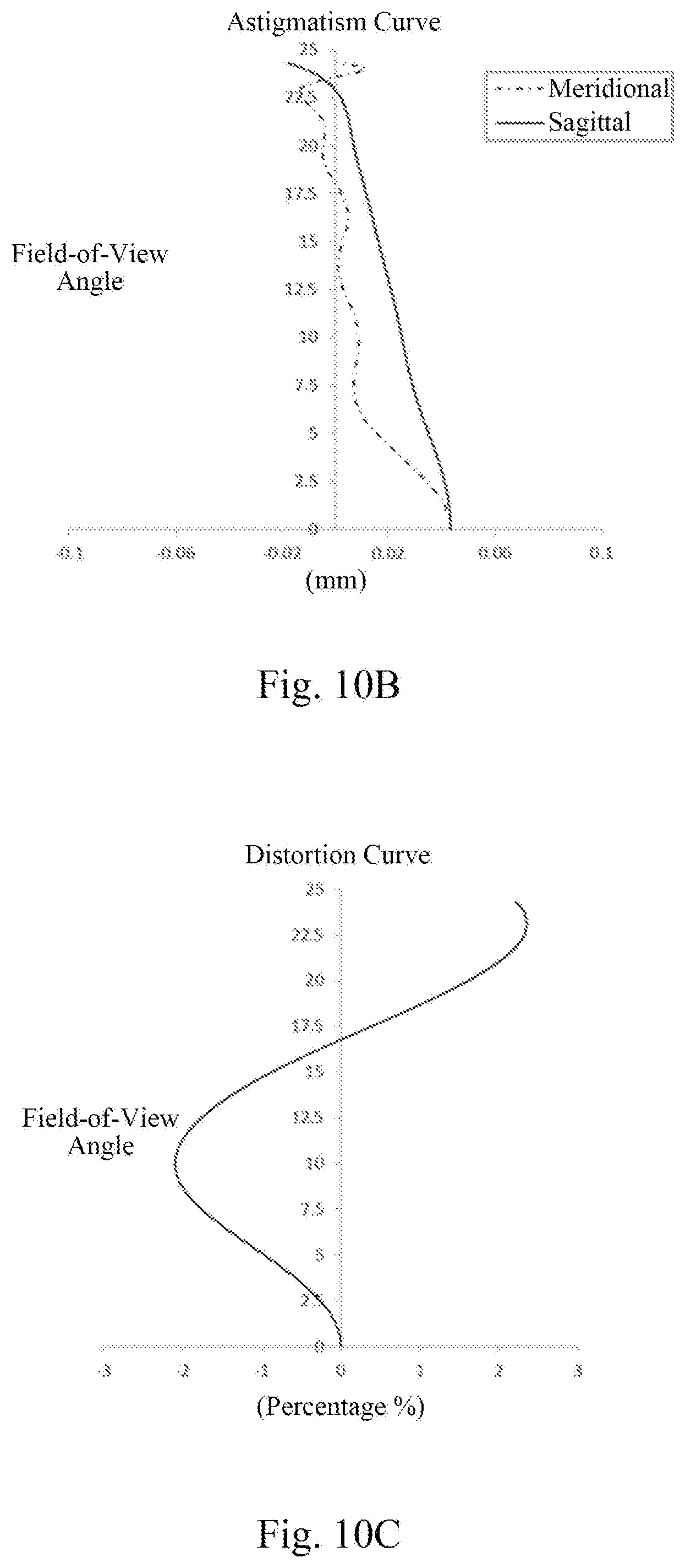
D00013

D00014
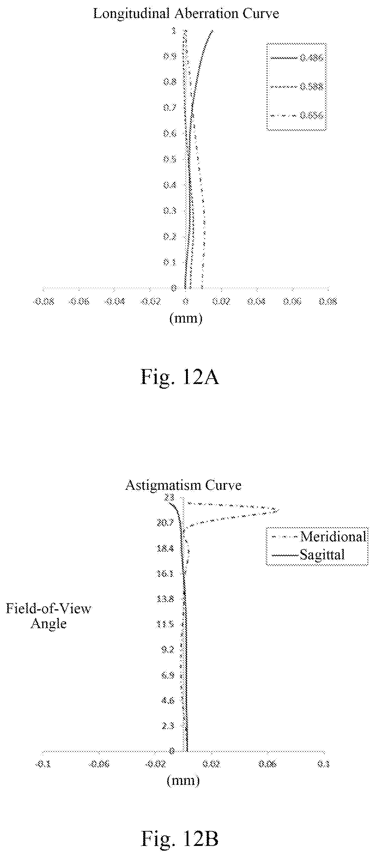
D00015
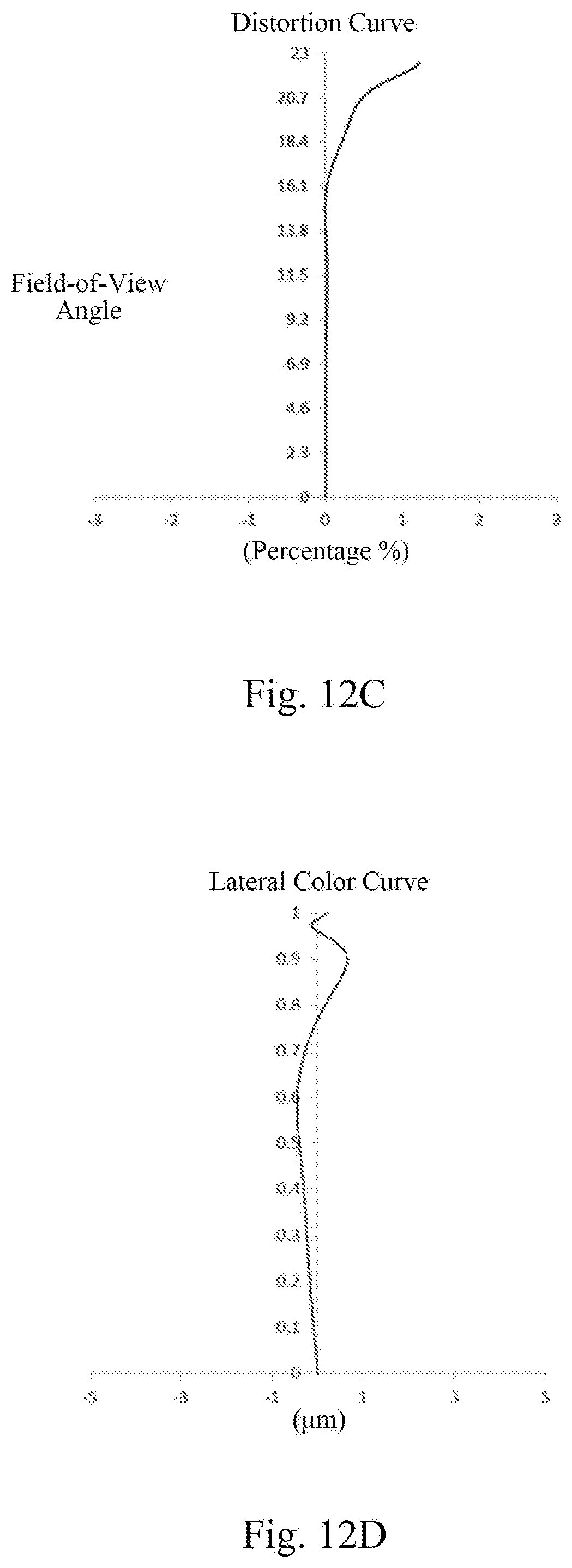
D00016

D00017

D00018
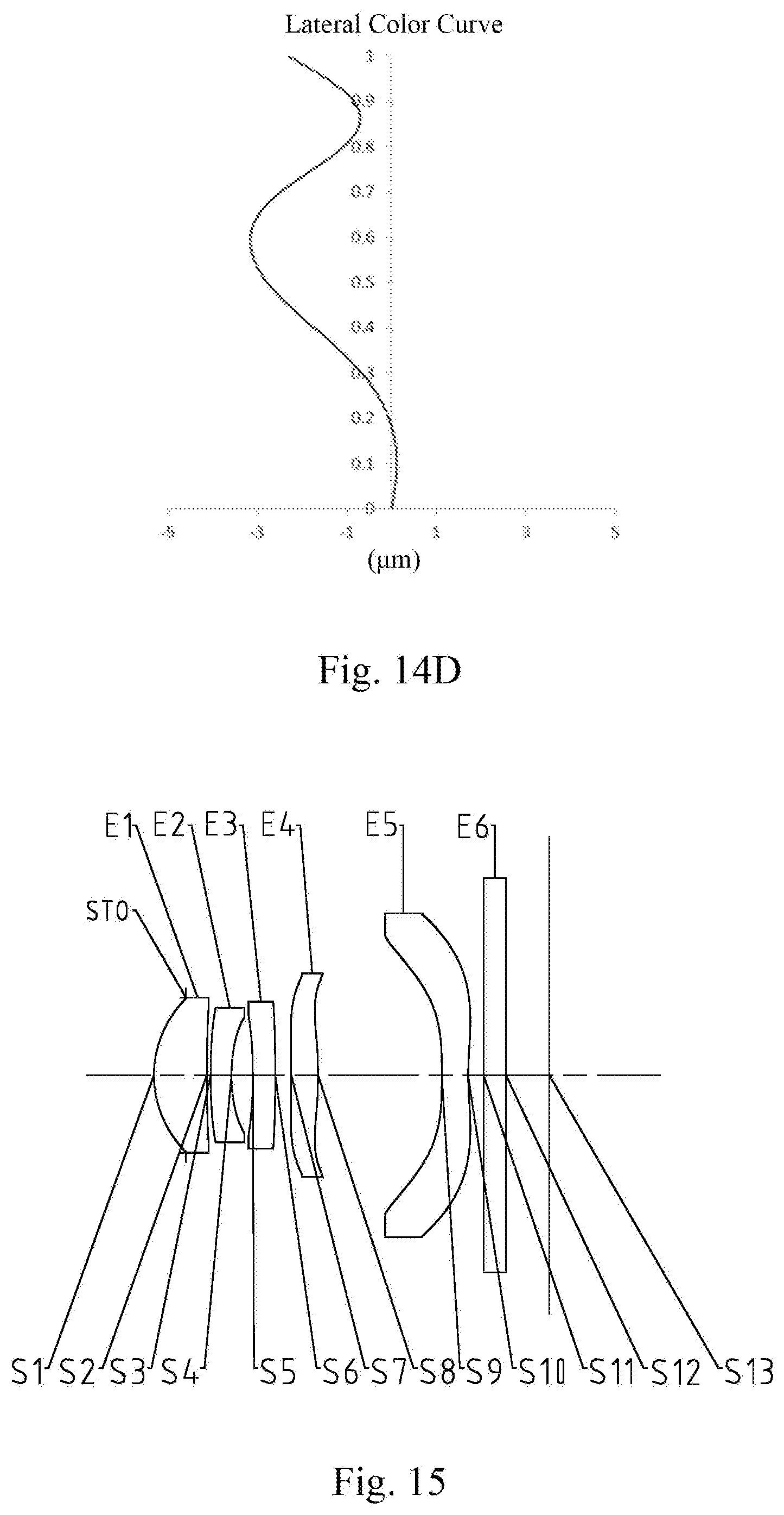
D00019

D00020

D00021

D00022
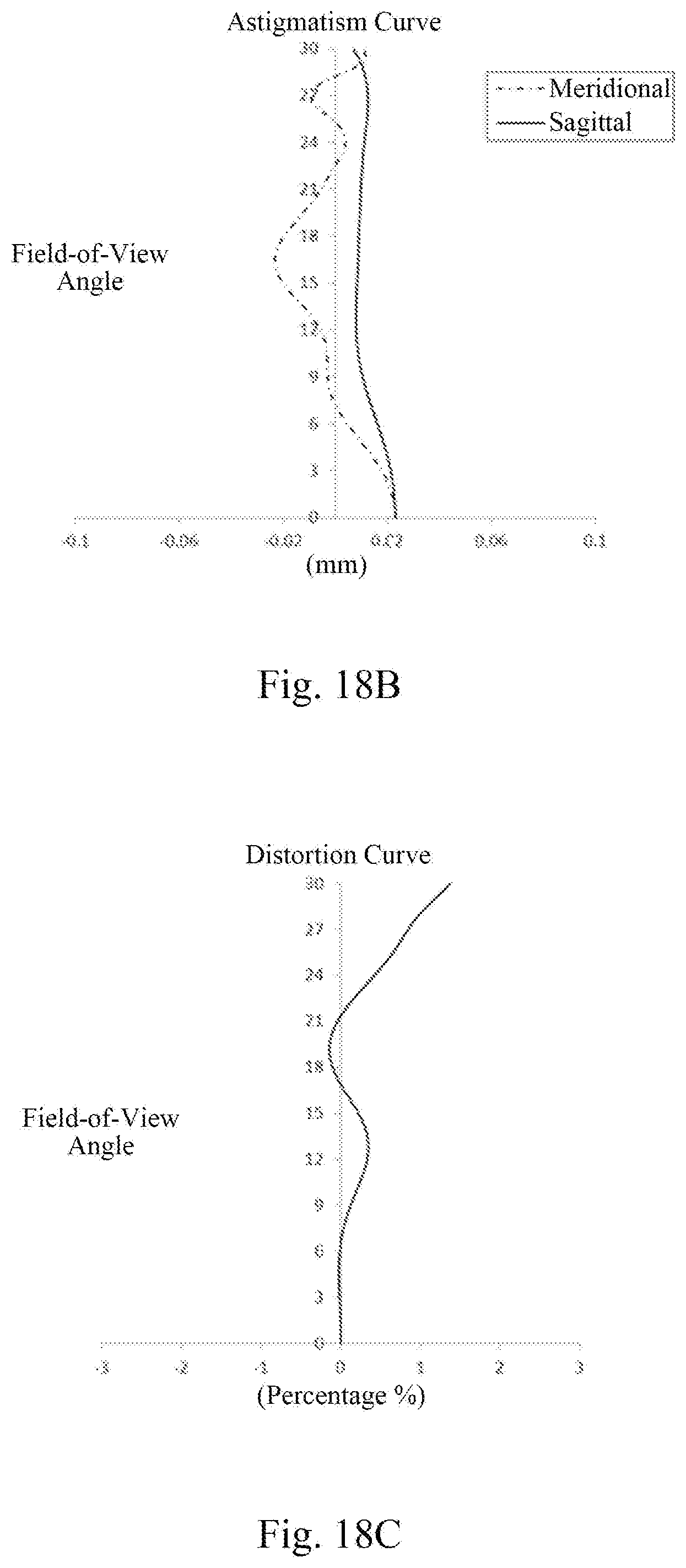
D00023

D00024
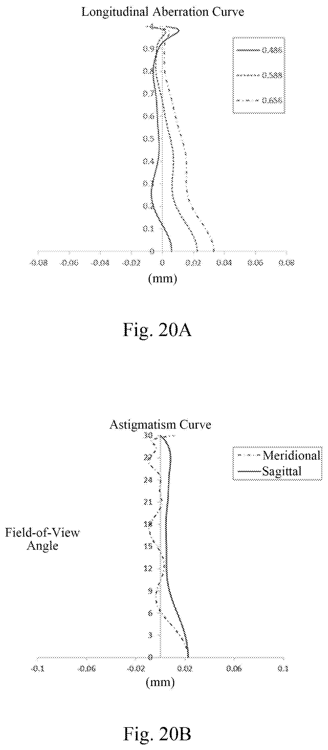
D00025
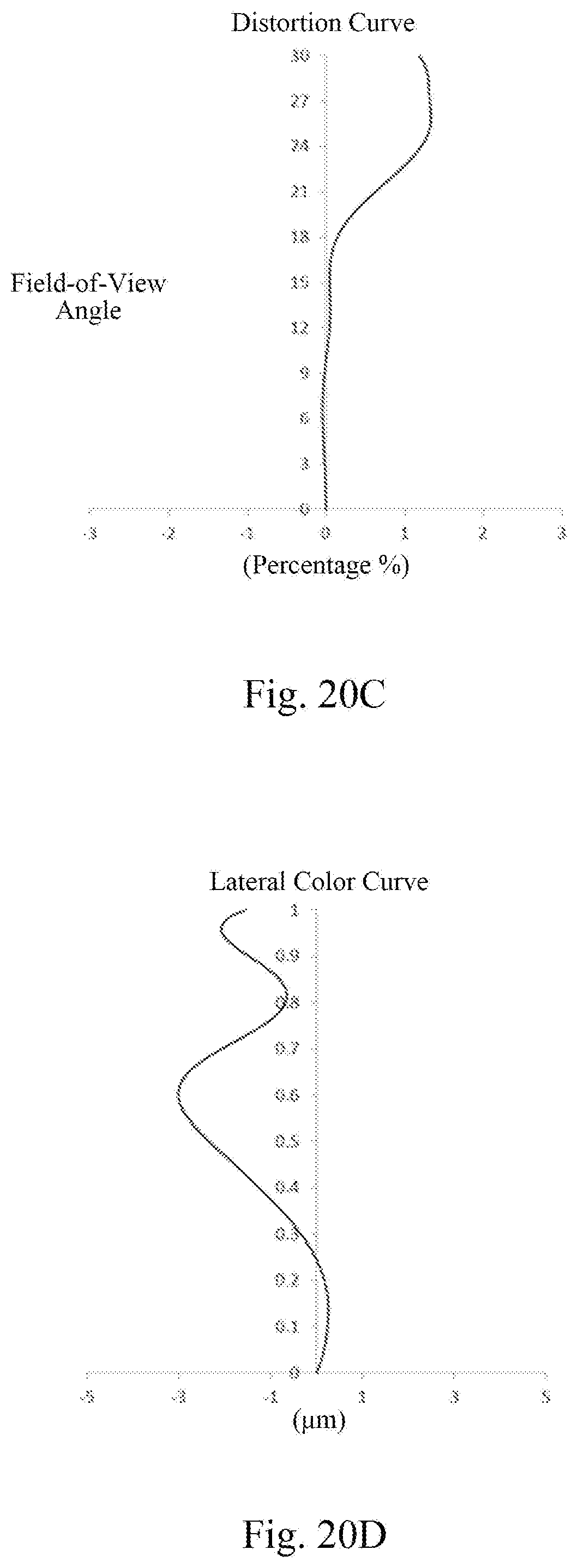
D00026

D00027

D00028
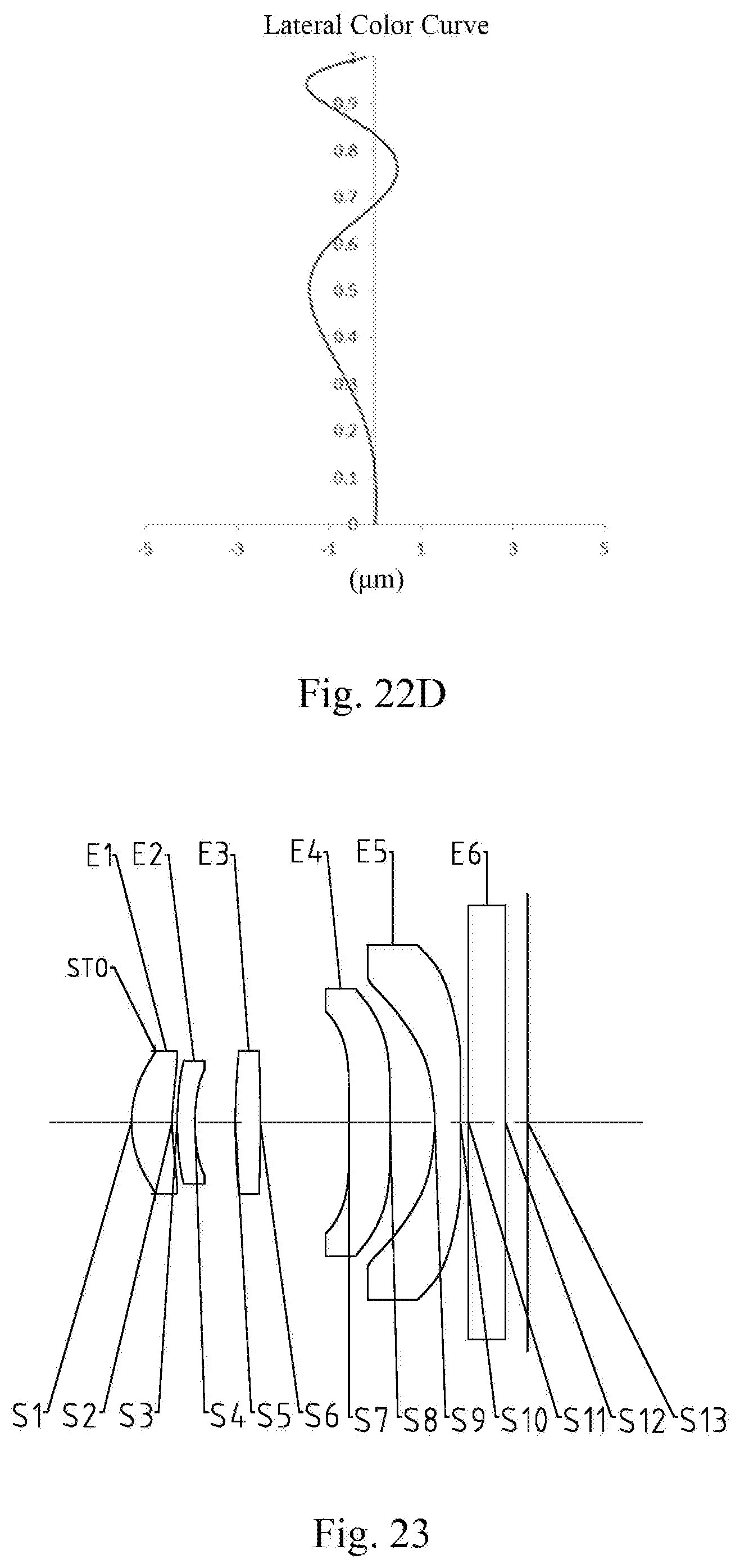
D00029

D00030

XML
uspto.report is an independent third-party trademark research tool that is not affiliated, endorsed, or sponsored by the United States Patent and Trademark Office (USPTO) or any other governmental organization. The information provided by uspto.report is based on publicly available data at the time of writing and is intended for informational purposes only.
While we strive to provide accurate and up-to-date information, we do not guarantee the accuracy, completeness, reliability, or suitability of the information displayed on this site. The use of this site is at your own risk. Any reliance you place on such information is therefore strictly at your own risk.
All official trademark data, including owner information, should be verified by visiting the official USPTO website at www.uspto.gov. This site is not intended to replace professional legal advice and should not be used as a substitute for consulting with a legal professional who is knowledgeable about trademark law.