Component Sensor
OKUDO; TAKAFUMI ; et al.
U.S. patent application number 16/639148 was filed with the patent office on 2020-07-23 for component sensor. The applicant listed for this patent is Panasonic Intellectual Property Management Co., Ltd.. Invention is credited to SHINICHI KISHIMOTO, MASAHIKO OHBAYASHI, TAKAFUMI OKUDO, KOJI SAKAI, HIROKI YOSHINO.
| Application Number | 20200232917 16/639148 |
| Document ID | / |
| Family ID | 66437900 |
| Filed Date | 2020-07-23 |
| United States Patent Application | 20200232917 |
| Kind Code | A1 |
| OKUDO; TAKAFUMI ; et al. | July 23, 2020 |
COMPONENT SENSOR
Abstract
A component sensor detects a fluid component with improved accuracy. The component sensor includes tube (3) including tube side (4) that permits inflow of fluid (2), substrate (5) provided to tube (3), first protrusion (6) provided at one end of substrate (5), second protrusion (7) provided at another end of substrate (5), light emitter (9) that emits infrared light (8) toward first protrusion (6), and light receiver (10) that receives infrared light (8). Infrared light (8) entering substrate (5) through first protrusion (6) experiences total reflection inside substrate (5) and exits through second protrusion (7) to head for light receiver (10). Tube side (4) includes two through holes (13) that each extend between an interior and an exterior of tube (3). Substrate (5) is inserted into through holes (13) with a central part of substrate (5) being inside tube (3) and with the one end and the other end of substrate (5) that are respectively provided with first protrusion (6) and second protrusion (7) being outside tube (3).
| Inventors: | OKUDO; TAKAFUMI; (Osaka, JP) ; KISHIMOTO; SHINICHI; (Osaka, JP) ; OHBAYASHI; MASAHIKO; (Osaka, JP) ; SAKAI; KOJI; (Hyogo, JP) ; YOSHINO; HIROKI; (Nara, JP) | ||||||||||
| Applicant: |
|
||||||||||
|---|---|---|---|---|---|---|---|---|---|---|---|
| Family ID: | 66437900 | ||||||||||
| Appl. No.: | 16/639148 | ||||||||||
| Filed: | October 25, 2018 | ||||||||||
| PCT Filed: | October 25, 2018 | ||||||||||
| PCT NO: | PCT/JP2018/039656 | ||||||||||
| 371 Date: | February 14, 2020 |
| Current U.S. Class: | 1/1 |
| Current CPC Class: | G01N 21/552 20130101; G01N 21/27 20130101; G01J 5/08 20130101; G01J 3/42 20130101; G01J 5/58 20130101; G01N 21/03 20130101; G01N 21/35 20130101 |
| International Class: | G01N 21/552 20060101 G01N021/552; G01N 21/03 20060101 G01N021/03; G01N 21/27 20060101 G01N021/27; G01N 21/35 20060101 G01N021/35; G01J 3/42 20060101 G01J003/42; G01J 5/08 20060101 G01J005/08; G01J 5/58 20060101 G01J005/58 |
Foreign Application Data
| Date | Code | Application Number |
|---|---|---|
| Nov 7, 2017 | JP | 2017-214414 |
Claims
1. A component sensor comprising: a tube including a tube side that allows a fluid to enter the tube; a substrate provided to the tube; a first protrusion provided at one end of the substrate; a second protrusion provided at another end of the substrate; a light emitter that emits infrared light toward the first protrusion; and a light receiver that receives the infrared light, wherein the infrared light entering the substrate through the first protrusion experiences total reflection inside the substrate and exits through the second protrusion to head for the light receiver, wherein the tube side includes two through holes that each extend between an interior and an exterior of the tube, and wherein the substrate is inserted into the two through holes with a central part of the substrate being inside the tube and with the one end and the other end of the substrate that are respectively provided with the first protrusion and the second protrusion being outside the tube.
2. The component sensor according to claim 1, wherein: the substrate includes a first principal surface and a second principal surface that is a back surface opposite from the first principal surface; and the first principal surface is not orthogonal to an extending direction of the tube.
3. The component sensor according to claim 2, wherein the first principal surface parallels the extending direction of the tube.
4. The component sensor according to claim 1, wherein: the substrate is sealed to the tube by a sealing member; and the sealing member is surfaced with a reflective film.
Description
TECHNICAL FIELD
[0001] The present disclosure relates to a device such as a fluid component detector that detects a level of a fluid component by utilizing a light absorption property such as an infrared absorption property.
BACKGROUND ART
[0002] A conventionally used component sensor includes a pipe through which fluid flows. A component sensor that uses a prism and an attenuated total reflection (ATR) method is known (PTL 1). A component sensor also known to use the ATR method has an infrared transmitting fiber passed through an interior of a sample container to achieve improved fluid component measurement performance (PTL 2 or 3).
CITATION LIST
Patent Literatures
[0003] PTL 1: Unexamined Japanese Patent Publication No. H07-020046
[0004] PTL 2: Unexamined Japanese Patent Publication No. S57-111423
[0005] PTL 3: Unexamined Japanese Patent Publication No. S57-111435
SUMMARY OF THE INVENTION
[0006] However, the component sensor disclosed in PTL 1 needs to be larger in size to achieve high sensitivity. While the conventional component sensor disclosed in PTL 2 or 3 can achieve, without becoming larger in size, improved sensitivity with an increased number of infrared absorptions, the infrared transmitting fiber being used is deformed by a moving sample, so that a component to be detected is detected with low accuracy.
[0007] Therefore, the present disclosure aims at solving the above problems and providing a component sensor that detects a target with improved accuracy.
[0008] To solve the above problems, a component sensor according to the present disclosure is configured as follows. The component sensor includes a tube including a tube side that allows a fluid to enter the tube, a substrate provided to the tube, a first protrusion provided at one end of the substrate, a second protrusion provided at another end of the substrate, a light emitter that emits infrared light toward the first protrusion, and a light receiver that receives the infrared light. The infrared light entering the substrate through the first protrusion experiences total reflection inside the substrate and exits through the second protrusion to head for the light receiver. The tube side is provided with two through holes that each extend between an interior and an exterior of the tube. The substrate is inserted into the through holes with a central part of the substrate being inside the tube. The one end and the other end of the substrate that are respectively provided with the first protrusion and the second protrusion are outside the tube.
[0009] Because of the above structure in which the substrate pierces through the tube, the present disclosure enables the component sensor to have improved sensitivity. The present disclosure also enables improved accuracy of detection of a component to be detected because the substrate that transmits the infrared light experiences less deformation.
BRIEF DESCRIPTION OF DRAWINGS
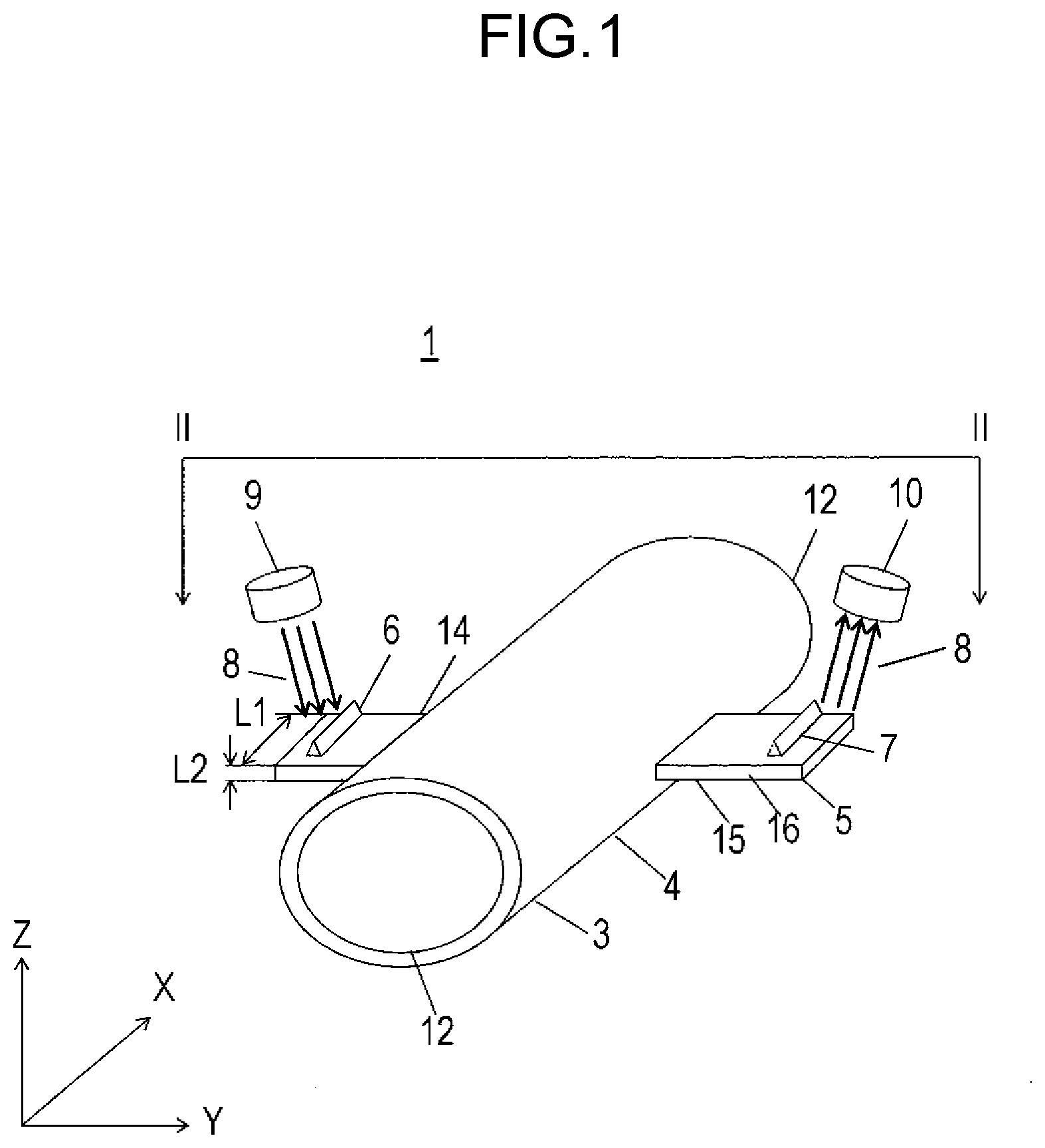
[0010] FIG. 1 is a perspective view of a component sensor according to an exemplary embodiment of the present disclosure.
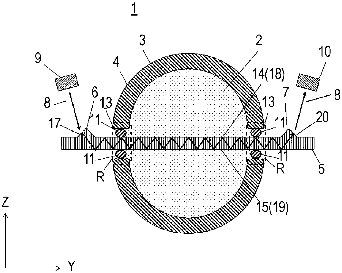
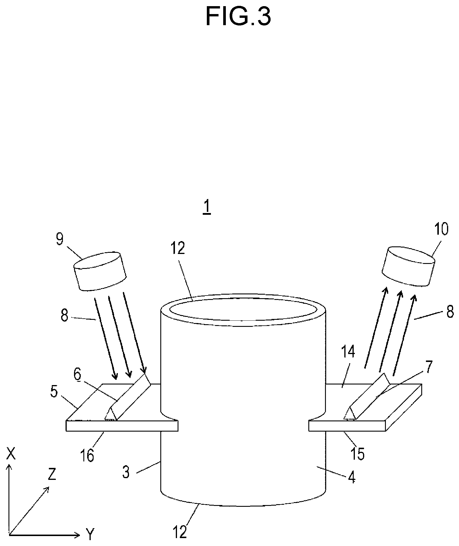
[0011] FIG. 2 is a sectional view of the component sensor, the section being taken along line II-II.
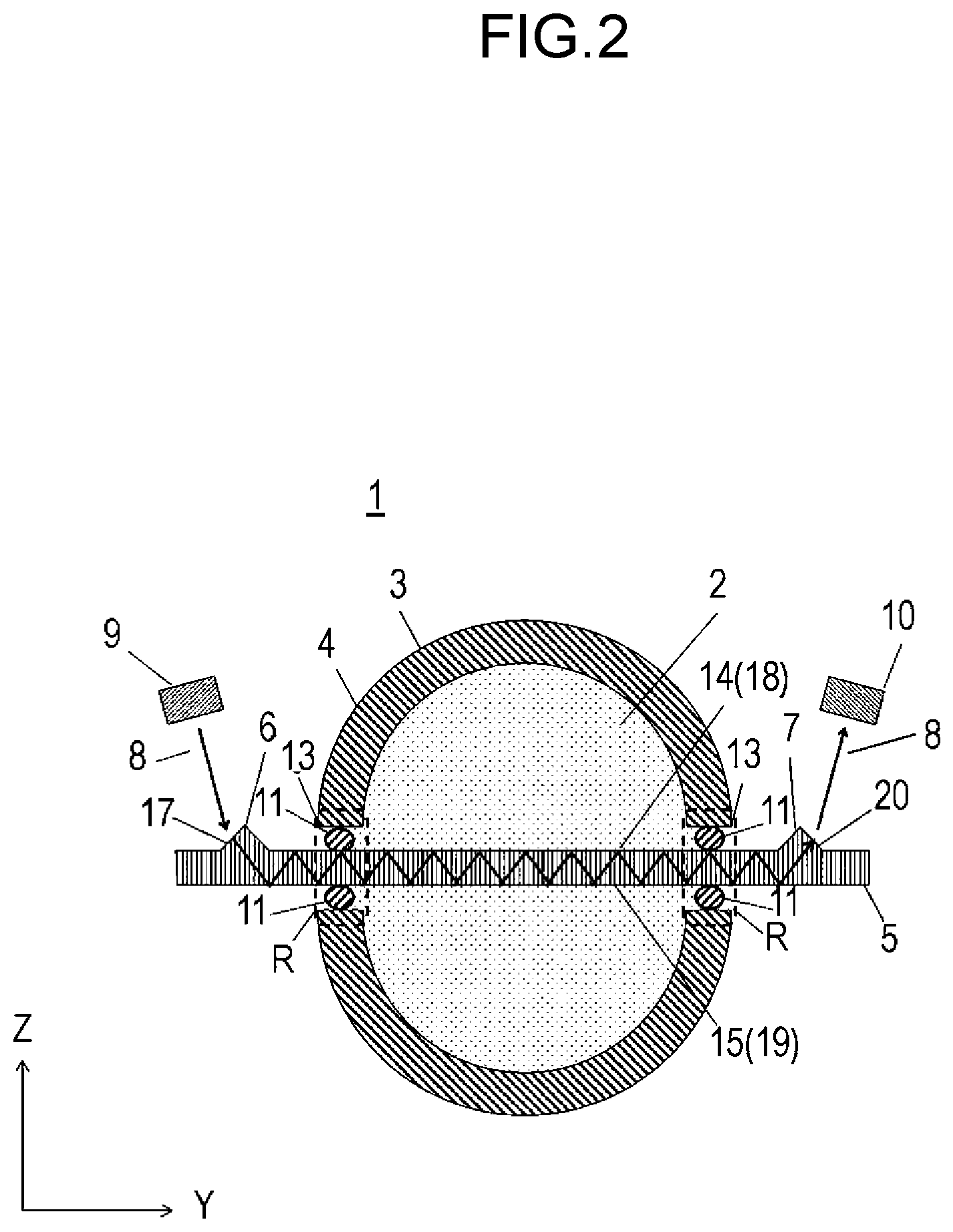
[0012] FIG. 3 is a perspective view of a modified example of the component sensor.
DESCRIPTION OF EMBODIMENT
Exemplary Embodiment
[0013] With reference to the drawings, a description is hereinafter provided of a component sensor according to the exemplary embodiment of the present disclosure.
[0014] FIG. 1 is a perspective view of the component sensor according to the exemplary embodiment. FIG. 2 is a sectional view of the component sensor, the section being taken along line II-II. A path of infrared light is indicated by straight lines. FIG. 2 illustrates a fluid which undergoes detection.
[0015] Component sensor 1 according to the exemplary embodiment includes tube 3 that permits inflow of fluid 2 which undergoes the detection, substrate 5 piercing through tube side 4 of tube 3 with both its ends being outside tube 3, first protrusion 6 provided at one of the ends of substrate 5, second protrusion 7 provided at the other end of substrate 5, light emitter 9 that emits infrared light 8 toward first protrusion 6, and light receiver 10 that receives infrared light 8 exiting through second protrusion 7. Substrate 5 is sealed to tube 3 by means of sealing members 11. Fluid 2 that undergoes detection is conceivably motor fuel. The fuel contains, for example, hydrocarbonaceous components, ethanol, and water. The hydrocarbonaceous components are, for example, aromatic, olefinic, and paraffinic. If levels of these fuel components are detected, improvement of fuel efficiency of an internal combustion engine and reduction of exhaust emissions, for example, can be achieved. Fluid 2 that undergoes detection, however, is not limited to this, and another fluid 2 may be used for detection of its component. An extending direction of tube 3 is hereinafter described as an X-axis direction, a direction connecting the ends of substrate 5 that project from tube 3 is hereinafter described as a Y-axis direction, and a direction orthogonal to both the X-axis and Y-axis directions is hereinafter described as a Z-axis direction.
[0016] Tube 3 is formed to be cylindrical and extends in the X-axis direction. Fluid 2 flows inside tube 3, so that a direction in which fluid 2 flows inside tube 3 is described as the extending direction of tube 3 in the description of component sensor 1. Tube 3 is not limited to being cylindrical and may be curved in shape. However, cylindrical tube 3 illustrated in FIG. 1 is used in the description of the exemplary embodiment. A section of tube 3 that is taken along a YZ plane is not limited to being circular in shape and may be, for example, elliptic, rectangular, or polygonal in shape. Tube 3 is provided with terminal openings 12 in the X-axis direction. Fluid 2 which undergoes the detection flows into or out from opening 12. Tube 3 has tube side 4 between two openings 12. Tube side 4 is provided with two through holes 13 that permit insertion of substrate 5, and substrate 5 is inserted into through holes 13. Substrate 5 has, in the Y-axis direction, a central part disposed inside tube 3. The one end and the other end of substrate 5 that are respectively provided with first protrusion 6 and second protrusion 7 are disposed outside tube 3 along the Y-axis direction.
[0017] Substrate 5 is made of silicon and has first principal surface 14, second principal surface 15, which is a back surface opposite from first principal surface 14, and substrate sides 16 positioned between first and second principal surfaces 14 and 15. Although silicon is not the only material for substrate 5, substrate 5 can be processed with ease when made of silicon. Areas of substrate 5 that are disposed outside tube 3 are provided with first protrusion 6 and second protrusion 7, respectively. First and second protrusions 6 and 7 are provided on first principal surface 14 of substrate 5 to be positioned on opposite sides of tube 3. First protrusion 6, tube 3, and second protrusion 7 of component sensor 1 are arranged in order in the Y-axis direction. Although first and second protrusions 6 and 7 are provided on first principal surface 14 of substrate 5, this is not limiting. For example, first protrusion 6 may be provided on first principal surface 14, while second protrusion 7 may be provided on second principal surface 15. First protrusion 6 and second protrusion 7 are prisms. First and second protrusions 6 and 7 are provided integrally with substrate 5 and thus can be formed with ease. First protrusion 6 is provided with first slope 17. Infrared light 8 enters substrate 5 through first slope 17 of first protrusion 6. Substrate 5 has a higher refractive index than fluid 2. For this reason, infrared light 8 entering substrate 5 through first protrusion 6 repeatedly experiences total reflection at first boundary surface 18 between first principal surface 14 of substrate 5 and fluid 2 as well as at second boundary surface 19 between second principal surface 15 and fluid 2 while heading for second protrusion 7. Infrared light 8 reaching second protrusion 7 exits substrate 5 through second slope 20 of second protrusion 7. First slope 17 and second slope 20 are formed by anisotropic etching. The anisotropic etching enables easy formation of first and second slopes 17, 20. When a (100) wafer is used as substrate 5, first slope 17 and second slope 20 become (111)-oriented planes each making angle .theta. of 54.7.degree. with second principal surface 15. If each of first and second slopes 17 and 20 makes angle .theta. of 54.7.degree. with second principal surface 15, infrared light 8 experiences total reflection at first and second boundary surfaces 18 and 19 each between substrate 5 and fluid 2. Angle .theta. which first and second slopes 17 and 20 each make with second principal surface 15 may be other than 54.7.degree.; however, the process can be easier to make first and second slopes 17 and 20 if angle .theta. is 54.7.degree..
[0018] Substrate 5 pierces through tube 3. Therefore, when infrared light 8 experiences the total reflection at first and second boundary surfaces 18 and 19, an evanescent wave penetrates into fluid 2 outwardly of substrate 5 and is attenuated by being absorbed by fluid 2. Detection of this attenuation enables detection of the component of fluid 2. Because silicon is used for substrate 5 of component sensor 1, substrate 5 is difficult to deform even under pressure of fluid 2. Therefore, compared with a conventional component sensor such as the one described in PTL 2 or 3, component sensor 1 has a small decline in detection accuracy that might be caused by deformation of substrate 5. Since infrared light 8 is absorbed by fluid 2 both at first and second boundary surfaces 18 and 19, an amount of infrared absorption is larger than when infrared light 8 is structurally absorbed only at either first principal surface 14 or second principal surface 15 as illustrated by the prior art in PTL 1. The amount of infrared absorption thus is doubled while infrared light 8 travels the same optical path length as infrared light 8 travels in the conventional component sensor. Therefore, component sensor 1 can have improved sensitivity. Because a length of substrate 5 can be halved with the sensitivity of component sensor 1 maintained, component sensor 1 can be miniaturized.
[0019] Each of first and second principal surfaces 14 and 15 has length L1 along a direction connecting two substrate sides 16 (length L1 is hereinafter described as a width of first principal surface 14 or second principal surface 15). This length L1 is greater than substrate side length L2 along a direction connecting first and second principal surfaces 14 and 15 (length L2 is hereinafter described as a width of each of substrate sides 16). It is to be noted that width L1 of first principal surface 14 and width L1 of second principal surface 15 are described as being equal for convenience of explanation, but are not limited to this. First principal surface 14 and second principal surface 15 are provided to parallel the extending direction (X-axis direction) of tube 3. Since width L1 of first principal surface 14 and width L1 of second principal surface 15 are each greater than width L2 of substrate side 16, when disposed with its first and second principal surfaces 14 and 15 paralleling the X-axis direction, substrate 5 can receive reduced pressure from fluid 2. Substrate 5 thus can undergo suppressed deformation under the pressure exerted by fluid 2. Therefore, component sensor 1 can have a suppressed decline in detection accuracy. FIG. 3 is a perspective view of a component sensor having differently disposed substrate 5. Although substrate 5 may be disposed with first principal surface 14 being orthogonal to the X-axis direction (with first and second principal surfaces 14 and 15 paralleling the YZ plane) as illustrated in FIG. 3, disposing substrate 5 so that first principal surface 14 is not orthogonal to the X-axis direction can reduce pressure of fluid 2. When disposed particularly with first principal surface 14 paralleling the X-axis direction as illustrated in FIG. 1, substrate 5 receives suitably minimized pressure from fluid 2. If tube 3 is curved, similar effects can be obtained when substrate 5 is disposed to receive minimized pressure from fluid 2.
[0020] Sealing members 11 are used to seal substrate 5 in seal regions R where through holes 13 are respectively provided. Used for sealing members 11 is metallic packing covered with a reflective film of gold, silver, or the like (not illustrated) that easily reflects infrared light 8. With sealing members 11 being covered with gold or silver, infrared light 8 experiences less attenuation when reflecting in the seal regions where sealing members 11 are used for sealing. Infrared light 8 may be attenuated by being absorbed by sealing members 11 when reflecting in the seal regions, and component sensor 1 may have correspondingly reduced sensitivity. However, with sealing members 11 being covered with gold or silver as in component sensor 1, infrared absorption by sealing members 11 can be suppressed, so that component sensor 1 can have improved sensitivity. It is to be noted that in order to prevent infrared reflection in seal regions R, an angle of infrared light 8 may be adjusted through adjustment of relative positions of light emitter 9 and first protrusion 6. When infrared light 8 is incident at such an angle, sealing members 11 do not absorb infrared light 8, so that component sensor 1 can have improved sensitivity.
[0021] A platinum film resistance element that is capable of emitting infrared light 8 is used as light emitter 9. A light-emitting diode that is capable of emitting infrared light 8 may be used instead. A semiconductor bare chip may be used as the light-emitting diode. Light emitter 9 is provided near first principal surface 14 of substrate 5 so that infrared light 8 is incident on first protrusion 6. Light emitter 9 emits infrared light 8 including a wavelength that is easily absorbed by fluid 2 that undergoes detection. Component sensor 1 uses infrared light 8 having those wavelengths ranging from 2 .mu.m to 15 .mu.m inclusive. The use of these wavelengths enables accurate detection of a level to be detected in fluid 2. It is to be noted that the wavelengths to be used may range more narrowly depending on intended use of component sensor 1. The wavelength range can be narrowed, for example, by means of an optical bandpass filter (not illustrated) that is consistent with an absorption wavelength specific to the fluid component to be measured. It is to be noted that light emitter 9 may include two or more light sources of different wavelengths. Use of the plurality of light emitters 9 enable detection of a plurality of component kinds in fluid 2.
[0022] Semiconductor bare chips are used for light receiver 10. Elements other than the semiconductor bare chips, such as pyroelectric elements or photodiodes, may be used for light receiver 10. Light receiver 10 is disposed in a position that enables detection of infrared light 8 exiting through second protrusion 7 on a substrate side of tube 3. Light receiver 10 includes two light receiving elements (not illustrated) and two optical filters (not illustrated) positioned to respectively correspond to the two light receiving elements. The two optical filters each transmit infrared light 8 including a different wavelength. One of the optical filters transmits infrared light 8 including the wavelength at which fluid 2 absorbs a large amount, while the other optical filter transmits infrared light 8 including the wavelength at which fluid 2 absorbs a small amount. The amount of infrared absorption by fluid 2 can be determined based on comparison between respective outputs of the two light receiving elements, so that the component of fluid 2 can be detected accurately. Although component sensor 1 uses the two light receiving elements and the two optical filters for the accurate detection of the component of fluid 2, it is to be noted that the component of fluid 2 can be detected even if one light receiving element and one optical filter are used. It is also to be noted that three or more light receiving elements and three or more optical filters may be provided. With an increased number of light receiving elements and an increased number of optical filters, an increased number of components kinds can be detected.
[0023] Although not illustrated, light emitter 9 and light receiver 10 are housed in a casing when mounted to tube 3 and are fixed so that infrared light 8 enters substrate 5 through first protrusion 6 and exits through second protrusion 7 to head for light receiver 10.
INDUSTRIAL APPLICABILITY
[0024] A component sensor according to the present disclosure can detect a fluid component with high accuracy and thus is suitable for detection of a level of a motor fuel component.
REFERENCE MARKS IN THE DRAWINGS
[0025] 1 component sensor [0026] 2 fluid [0027] 3 tube [0028] 4 tube side [0029] 5 substrate [0030] 6 first protrusion [0031] 7 second protrusion [0032] 8 infrared light [0033] 9 light emitter [0034] 10 light receiver [0035] 11 sealing member [0036] 12 opening [0037] 13 through hole [0038] 14 first principal surface [0039] 15 second principal surface [0040] 16 substrate side [0041] 17 first slope [0042] 18 first boundary surface [0043] 19 second boundary surface [0044] 20 second slope
* * * * *
D00000
D00001
D00002
D00003
XML
uspto.report is an independent third-party trademark research tool that is not affiliated, endorsed, or sponsored by the United States Patent and Trademark Office (USPTO) or any other governmental organization. The information provided by uspto.report is based on publicly available data at the time of writing and is intended for informational purposes only.
While we strive to provide accurate and up-to-date information, we do not guarantee the accuracy, completeness, reliability, or suitability of the information displayed on this site. The use of this site is at your own risk. Any reliance you place on such information is therefore strictly at your own risk.
All official trademark data, including owner information, should be verified by visiting the official USPTO website at www.uspto.gov. This site is not intended to replace professional legal advice and should not be used as a substitute for consulting with a legal professional who is knowledgeable about trademark law.