Cup Lid
PAN; WEI CHIH
U.S. patent application number 16/177850 was filed with the patent office on 2020-05-07 for cup lid. The applicant listed for this patent is WEI CHIH PAN. Invention is credited to WEI CHIH PAN.
| Application Number | 20200140159 16/177850 |
| Document ID | / |
| Family ID | 70458395 |
| Filed Date | 2020-05-07 |


| United States Patent Application | 20200140159 |
| Kind Code | A1 |
| PAN; WEI CHIH | May 7, 2020 |
CUP LID
Abstract
A cup lid includes a main body, a spout section, a first leaning seat and a second leaning seat. The spout section, the first leaning seat and the second leaning seat are disposed on a top wall of the main body and spaced away from each other. A first clamping interval is formed between the first leaning seat and the supporting portion. A second clamping interval is formed between the second leaning end and the supporting portion. The first clamping interval and the second clamping interval are configured to retain a communication device in a prop-up state in two different directions, respectively, so as to selectively show another user the communication device. Therefore, it increases the functionalities and the additional values of the cup lid.
| Inventors: | PAN; WEI CHIH; (TAOYUAN CITY, TW) | ||||||||||
| Applicant: |
|
||||||||||
|---|---|---|---|---|---|---|---|---|---|---|---|
| Family ID: | 70458395 | ||||||||||
| Appl. No.: | 16/177850 | ||||||||||
| Filed: | November 1, 2018 |
| Current U.S. Class: | 1/1 |
| Current CPC Class: | B65D 2543/00527 20130101; B65D 51/24 20130101; B65D 43/0202 20130101; B65D 43/0212 20130101; B65D 2543/00537 20130101; B65D 2543/00046 20130101; B65D 2231/022 20130101; B65D 2543/00009 20130101; B65D 2543/00092 20130101 |
| International Class: | B65D 51/24 20060101 B65D051/24; B65D 43/02 20060101 B65D043/02 |
Claims
1. A cup lid, comprising: a main body; a spout section, disposed on a top wall of the main body and having a supporting portion; a first leaning seat, disposed on the top wall of the main body, wherein two ends of the first leaning seat respectively have a first leaning end, the two first leaning ends are aligned in a first leaning line, and a first clamping interval is formed between the first leaning line and the supporting portion; and a second leaning seat, disposed on the top wall of the main body, wherein two ends of the second leaning seat respectively have a second leaning end, the two second leaning ends are aligned in a second leaning line, and a second clamping interval is formed between the second leaning line and the supporting portion; wherein the first leaning seat, the second leaning seat and the spout section are spaced away from each other, the spout section is disposed between the first leaning seat and the second leaning seat.
2. The cup lid according to claim 1, wherein the main body, the spout section, the first leaning seat and the second leaning seat are formed integrally in one piece.
3. The cup lid according to claim 1, wherein the main body has a circumferential skirt protruded from the top wall, the spout section is disposed in an inner region of the circumferential skirt, the first leaning seat and the second leaning seat are disposed on the circumferential skirt.
4. The cup lid according to claim 3, wherein the first leaning seat is arc-shaped, each of the first leaning ends is formed with a first chamfer surface, and an acute angle is formed between the first chamfer surface and an inner edge of the circumferential skirt.
5. The cup lid according to claim 4, wherein the second leaning seat is arc-shaped, and each of the second leaning ends is formed with a second chamfer surface, and an acute angle is formed between the second chamfer surface and an inner edge of the circumferential skirt.
6. The cup lid according to claim 5, wherein a length of the first clamping interval is substantially equal to a length of the second clamping interval.
7. The cup lid according to claim 5, wherein a length of the first clamping interval is larger than a length of the second clamping interval.
8. The cup lid according to claim 5, wherein a height of the spout section is higher than a height of the first leaning seat.
9. The cup lid according to claim 5, wherein a height of the spout section is higher than a height of the second leaning seat.
10. The cup lid according to claim 5, wherein a height of the spout section is respectively higher than a height of the first leaning seat, and a height of the second leaning seat.
11. The cup lid according to claim 5, wherein the first leaning seat and the second leaning seat are symmetrical to each other.
12. The cup lid according to claim 11, wherein the first leaning seat and the second leaning seat are symmetrical to each other about a center of the spout section.
13. The cup lid according to claim 3, wherein the cup lid further includes a third leaning seat, the third leaning seat is protrudedly formed from the top wall of the main body, two ends of the third leaning seats respectively have a third leaning end, the two third leaning ends are aligned in a third leaning line, and a third clamping interval is formed between the third leaning line and the supporting portion.
14. The cup lid according to claim 13, wherein the third leaning seat is arc-shaped, each of the third leaning ends is formed with a third chamfer surface, and an acute angle is formed between the third chamfer surface and the circumferential skirt.
15. The cup lid according to claim 13, wherein a length of the first clamping interval, a length of the second clamping interval, and a length of the third clamping interval are equal to each other.
16. The cup lid according to claim 13, wherein a length of the first clamping interval is larger than a length of the second clamping interval, and the length of the second clamping interval is larger than a length of the third clamping interval.
17. The cup lid according to claim 13, wherein a height of the spout section is higher than a height of the first leaning seat.
18. The cup lid according to claim 13, wherein a height of the spout section is higher than a height of the second leaning seat.
19. The cup lid according to claim 13, wherein a height of the spout section is higher than a height of the third leaning seat.
20. The cup lid according to claim 13, wherein a height of the spout section is respectively higher than a height of the first leaning seat, a height of the second leaning seat, and a height of the third leaning seat.
21. The cup lid according to claim 13, wherein the spout section has a plurality of slanted lateral surfaces connected to each other along a periphery thereof to form a polygon pyramid.
22. The cup lid according to claim 21, wherein the first leaning seat, the second leaning seat and the third leaning seat are respectively faced one of the slanted lateral surfaces.
23. The cup lid according to claim 22, wherein the slanted lateral surfaces respectively have different slopes.
24. The cup lid according to claim 23, wherein the spout section is a cone and the top surface of the spout section is plane.
25. The cup lid according to claim 24, wherein the spout section is formed with a drink-through hole.
Description
FIELD OF THE DISCLOSURE
[0001] The present disclosure is related to a cup lid, and more particularly to a cup lid which can retain a communication device in a propped-up state on a top surface of the cup lid.
BACKGROUND OF THE DISCLOSURE
[0002] Cup has become an indispensable vessel to people for receiving water or drink. Because of the well-developed technology, the technology of manufacturing the cup has been established. Cup can be found everywhere in our society nowadays, no matter at home, breakfast shop, office, and restaurant. Even on the road, some people hold a cup filled with drink.
[0003] In order to meet the daily needs of people as mentioned above, the cup lid is developed successively in various materials and shapes, for covering an opening of the cup, to avoid spilling water or drink in the cup. However, the conventional cup lid only has the single function of sealing the opening of the cup, the usage frequency is less, and is discarded immediately after use. Therefore, if the functionalities of the cup lid can be increased, it not only increases the additional value of the cup lid, but also reduces the possibility of discard of cup lid.
SUMMARY OF THE DISCLOSURE
[0004] In response to the above-referenced technical inadequacies, the present disclosure provides a cup lid being able to retain a communication device in a propped-up state on a top surface of the cup lid.
[0005] In one aspect, the present disclosure provides a cup lid, which includes a main body, a spout section, a first leaning seat, and a second leaning seat. The spout section is disposed on a top wall of the main body and having a supporting portion. The first leaning seat is disposed on the top wall of the main body. Two ends of the first leaning seat respectively have a first leaning end. The two first leaning ends are aligned in a first leaning line. A first clamping interval is formed between the first leaning line and the supporting portion. The second leaning seat is disposed on the top wall of the main body. Two ends of the second leaning seat respectively have a second leaning end. The two second leaning ends are aligned in a second leaning line. A second clamping interval is formed between the second leaning line and the supporting portion. The first leaning seat, the second leaning seat and the spout section are spaced away from each other. The spout section is disposed between the first leaning seat and the second leaning seat.
[0006] According to one exemplary embodiment of the present disclosure, wherein the main body, the spout section, the first leaning seat, and the second leaning seat are formed integrally in one piece.
[0007] According to one exemplary embodiment of the present disclosure, wherein the main body has a circumferential skirt protruded from the top wall of the main body, the spout section is disposed in an inner region of the circumferential skirt, the first leaning seat and the second leaning seat are disposed on the circumferential skirt.
[0008] According to one exemplary embodiment of the present disclosure, wherein the first leaning seat is arc-shaped, each of the first leaning ends is formed with a first chamfer surface, and an acute angle is formed between the first chamfer surface and an inner edge of the circumferential skirt.
[0009] According to one exemplary embodiment of the present disclosure, wherein the second leaning seat is arc-shaped, and each of the second leaning ends is formed with a second chamfer surface, and an acute angle is formed between the second chamfer surface and an inner edge of the circumferential skirt.
[0010] According to one exemplary embodiment of the present disclosure, wherein a length of the first clamping interval is substantially equal to a length of the second clamping interval.
[0011] According to one exemplary embodiment of the present disclosure, wherein a length of the first clamping interval is larger than a length of the second clamping interval.
[0012] According to one exemplary embodiment of the present disclosure, wherein a height of the spout section is higher than a height of the first leaning seat.
[0013] According to one exemplary embodiment of the present disclosure, wherein a height of the spout section is higher than a height of the second leaning seat.
[0014] According to one exemplary embodiment of the present disclosure, wherein a height of the spout section is respectively higher than a height of the first leaning seat, and a height of the second leaning seat.
[0015] According to one exemplary embodiment of the present disclosure, wherein the first leaning seat and the second leaning seat are symmetrical to each other.
[0016] According to one exemplary embodiment of the present disclosure, wherein the first leaning seat and the second leaning seat are symmetrical to each other about a center of the spout section.
[0017] According to one exemplary embodiment of the present disclosure, wherein the cup lid further includes a third leaning seat, the third leaning seat is protrudedly formed from the top wall of the main body, two ends of the third leaning seats respectively have a third leaning end, the two third leaning ends are aligned in a third leaning line, and a third clamping interval is formed between the third leaning line and the supporting portion.
[0018] According to one exemplary embodiment of the present disclosure, wherein the third leaning seat is arc-shaped, each of the third leaning ends is formed with a third chamfer surface, and an acute angle is formed between the third chamfer surface and the circumferential skirt.
[0019] According to one exemplary embodiment of the present disclosure, wherein a length of the first clamping interval, a length of the second clamping interval, and a length of the third clamping interval are substantially equal to each other.
[0020] According to one exemplary embodiment of the present disclosure, wherein a length of the first clamping interval is larger than a length of the second clamping interval, and the length of the second clamping interval is equal to a length of the third clamping interval.
[0021] According to one exemplary embodiment of the present disclosure, wherein a height of the spout section is higher than a height of the third leaning seat.
[0022] According to one exemplary embodiment of the present disclosure, wherein a height of the spout section is respectively higher than a height of the first leaning seat, a height of the second leaning seat, and a height of the third leaning seat.
[0023] According to one exemplary embodiment of the present disclosure, wherein the spout section is a polygon pyramid and has a plurality of slanted lateral surfaces.
[0024] According to one exemplary embodiment of the present disclosure, wherein the first leaning seat, the second leaning seat and the third leaning seat are respectively faced one of the slanted lateral surfaces.
[0025] According to one exemplary embodiment of the present disclosure, wherein the slanted lateral surfaces respectively have different slopes.
[0026] According to one exemplary embodiment of the present disclosure, wherein the spout section is a cone and the top surface of the spout section is plane.
[0027] According to one exemplary embodiment of the present disclosure, wherein the spout section is formed with a drink-through hole.
[0028] The cup lid of the present disclosure not only has a basic function of sealing an opening of a cup, but also an additional function of clamping a communication device in one of the clamping intervals which are respectively formed between the spout section and the leaning seats spacing away on the top wall of the main body of the cup lid. Therefore, the communication device is retained in a propped-up state so as to conveniently show a user the screen of the communication device. In addition, the clamping intervals of the present disclosure can be designed to be different between the leaning seats and the spout section. The user can select one specified clamping interval according to a required inclination angle of the mobile phone in a propped-up state, so as to enhance the convenience of use.
[0029] These and other aspects of the present disclosure will become apparent from the following description of the embodiment taken in conjunction with the following drawings and their captions, although variations and modifications therein may be affected without departing from the spirit and scope of the novel concepts of the disclosure.
BRIEF DESCRIPTION OF THE DRAWINGS
[0030] The present disclosure will become more fully understood from the following detailed description and accompanying drawings.
[0031] FIG. 1 is a first schematic view of a cup lid according to a first embodiment of the present disclosure;
[0032] FIG. 2 is a second schematic view of the cup lid according to the first embodiment of the present disclosure;
[0033] FIG. 3 is a third schematic view of the cup lid according to a first embodiment the present disclosure;
[0034] FIG. 4 is a first schematic view of the cup lid according to a second embodiment of the present disclosure;
[0035] FIG. 5 is a second schematic view of the cup lid according to the second embodiment the present disclosure;
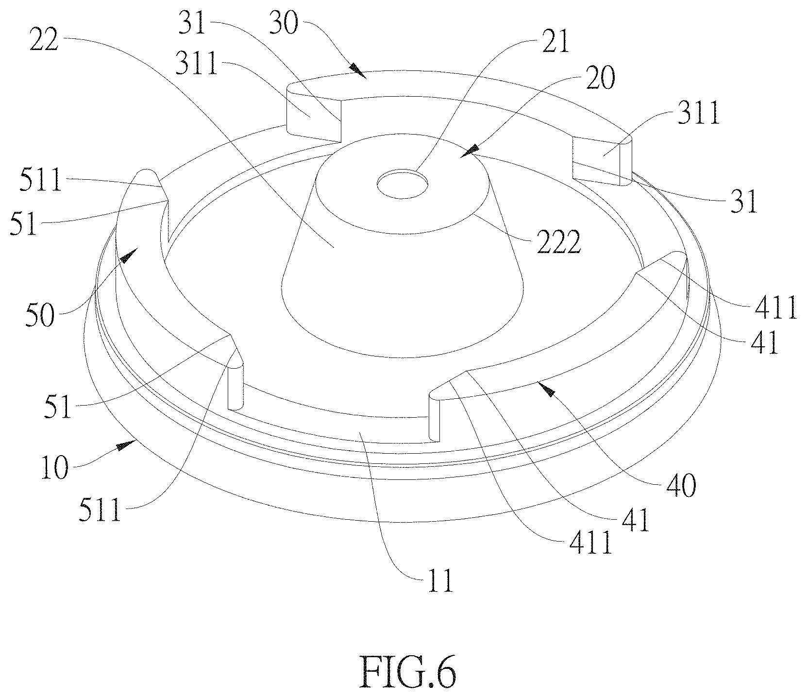
[0036] FIG. 6 is a first schematic view of the cup lid according to a third embodiment of the present disclosure;
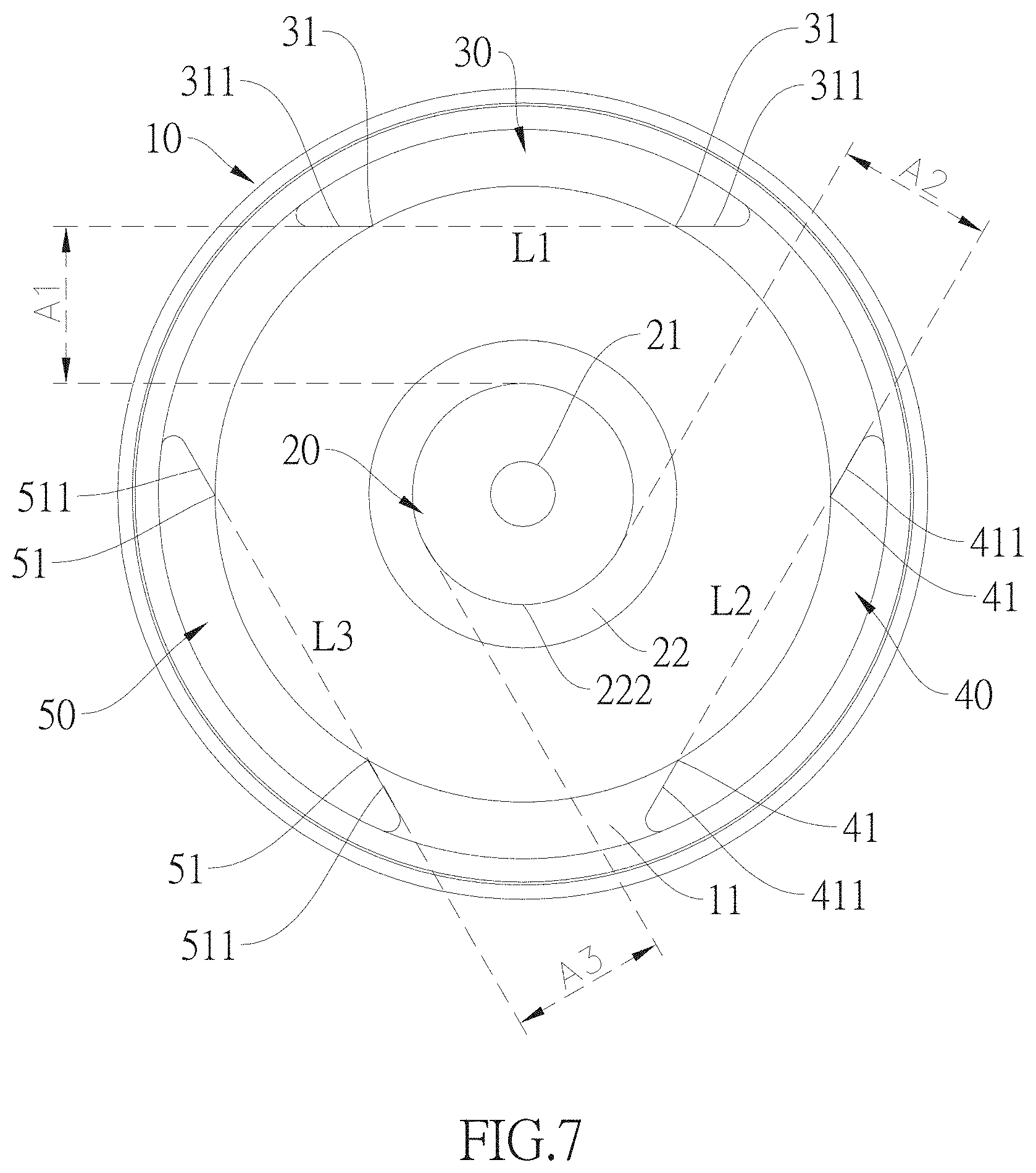
[0037] FIG. 7 is a second schematic view of the cup lid according to the third embodiment of the present disclosure;
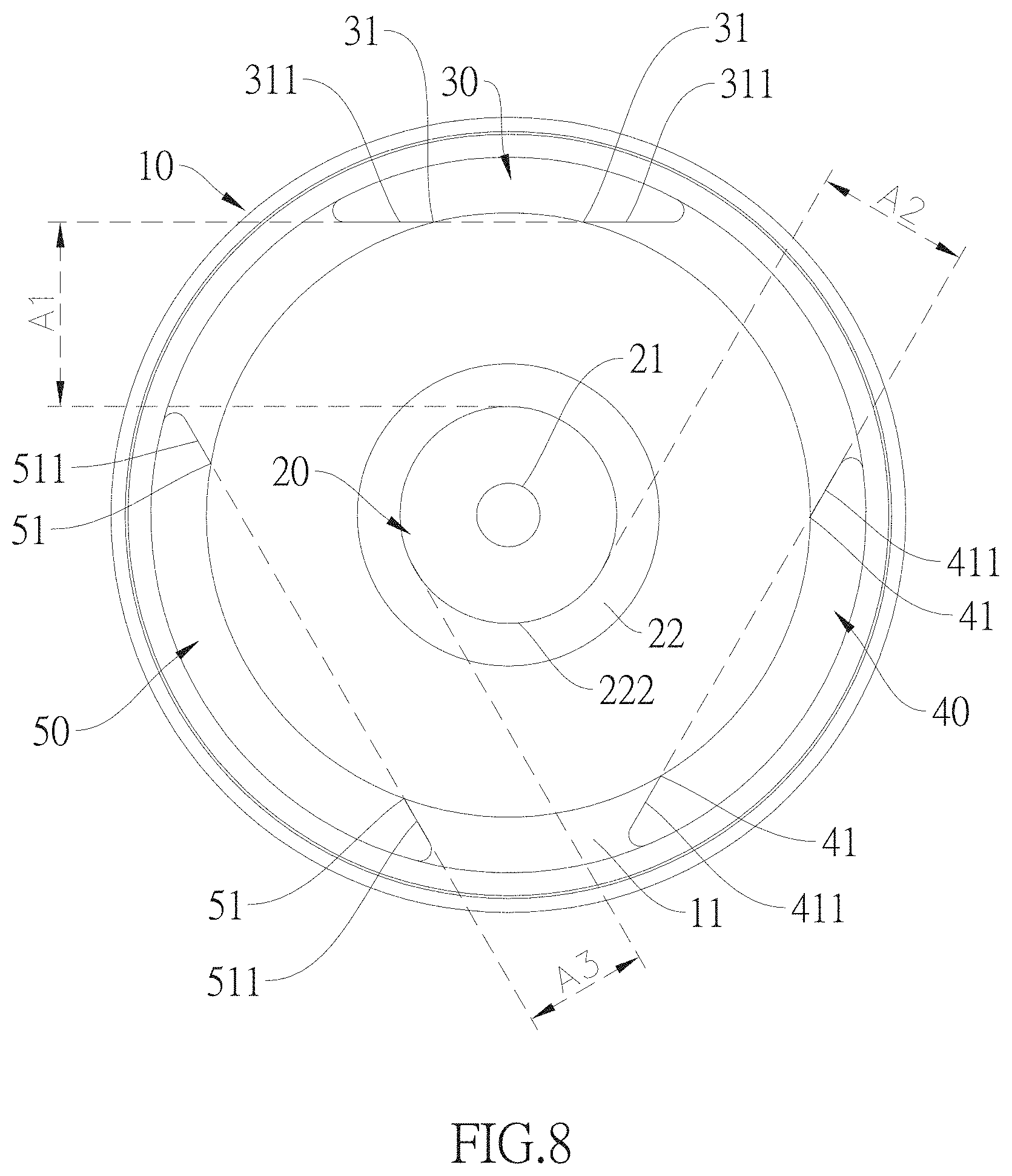
[0038] FIG. 8 is a schematic view of the cup lid according to a fourth embodiment of the present disclosure; and
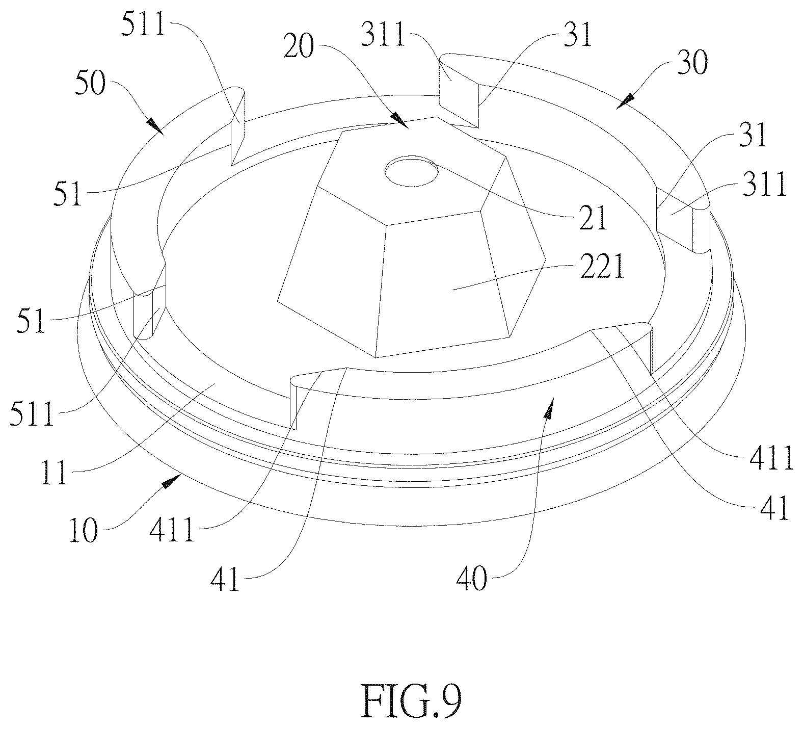
[0039] FIG. 9 is a schematic view of the cup lid according to a fifth embodiment of the present disclosure.
DETAILED DESCRIPTION OF THE EXEMPLARY EMBODIMENTS
[0040] The present disclosure is more particularly described in the following examples that are intended as illustrative only since numerous modifications and variations therein will be apparent to those skilled in the art. Other objectives and advantages related to the present disclosure will be illustrated in the subsequent descriptions and appended drawings.
First Embodiment
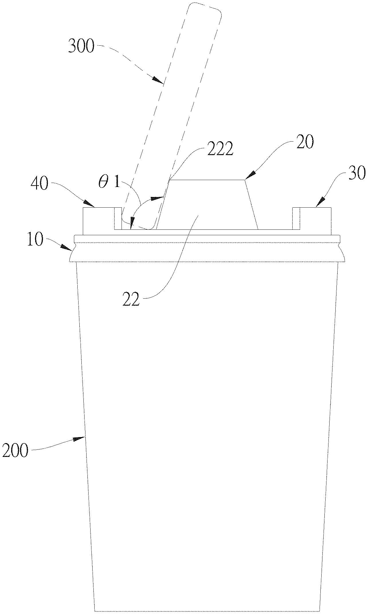
[0041] Referring to FIG. 1 to FIG. 3, which are a perspective view and a top view of a cup lid, and a side view of the cup lid on a cup according to the first embodiment of the present disclosure. The present disclosure provides a cup lid, which not only has a function of sealing an opening of a cup, but also an additional function of retaining a communication device, such as mobile phone, or tablet computer, in a propped-up state, so as to increase the value and the usable frequency of the cup lid. Therefore, the amount of disposed cup lid can be reduced to benefit the environment. As shown in FIG. 1, the cup lid includes a main body 10, a spout section 20, a first leaning seat 30 and a second leaning seat 40. The main body 10 of this embodiment has a top wall and a rim engaging portion to engage with a cup. The spout section 20 is disposed between the first leaning seat 30 and the second leaning seat 40. The first leaning seat 30, the second leaning seat 40, and the spout section 20 are spaced away from each other. It is preferable that the first leaning seat 30 and the second leaning seat 40 are symmetrical to each other. In addition, the first leaning seat 30 the second leaning seat 40 are symmetrical to each other about a center of the spout section 20. The spout section 20 is preferably disposed at a center of the top wall of the main body 10. The spout section 20 is protrudedly formed on the top wall of the main body 10 and has a supporting portion 22. The first leaning seat 30 is protrudedly formed on the top wall of the main body 10. Two ends of the first leaning seat 30 respectively have a first leaning end 31, and the two first leaning ends 31 are aligned in a first leaning line L1. A first clamping interval A1 is formed between the first leaning line L1 and the supporting portion 22. The second leaning seat 40 is protrudedly formed on the top wall of the main body 10. Two ends of the second leaning seat 40 respectively have a second leaning end 41, and the two second leaning ends 41 are aligned in a second leaning line L2. A second clamping interval A2 is formed between the second leaning line L2 and the supporting portion 22. The first clamping interval A1 or the second clamping interval A2 allows a user to put a communication device 300, such as a smartphone, to be retained in a prop-up state, as shown in FIG. 3. Therefore, the cup lid of the present disclosure allows the user to put a smartphone in a propped-up state in two different directions selectively, so as to show another user the screen of the smartphone, without rotating the cup lid or cup, to avoid spilling the cup. Preferably, the main body 10, the spout section 20, the first leaning seat 30 and the second leaning seat 40 are integrally formed in one piece. In addition, the spout section 20 is disposed between the first leaning line L1 and the second leaning line L2. The spout section 20 is formed with a drink-through hole 21, as shown in FIG. 4, to allow a suction tube inserted therein.
[0042] An additional note is that, the first clamping interval A1 and the second clamping interval A2 are varied according to the shapes and sizes of the spout section 20, the first leaning seat 30 and the second leaning seat 40, or varied according to the configurated positions of the spout section 20 on the main body 10. For example, when the first leaning seat 30 and the second leaning seat 40 have identical shape and size arranged annularly in an equidistant manner, and the spout section 20 of column-shaped is disposed on a center defined annularly by the first leaning seat 30 and the second leaning seat 40, the first clamping interval A1 and the second clamping interval A2 are identical.
[0043] The top wall of the main body 10 further has a protruded circumferential skirt 11. The spout section 20 is disposed in an inner region surrounded by the circumferential skirt 11. The first leaning seat 30 and the second leaning seat 40 are disposed on the circumferential skirt 11. The first leaning seat 30 and the second leaning seat 40 are arc-shaped. The two first leaning ends 31 of the arc-shaped first leaning seat 30 respectively are formed with a first chamfer surface 311, and an acute angle is defined between the first chamfer surface 311 and an inner edge of the circumferential skirt 11. The two second leaning ends 41 of the second leaning seat 40 respectively are formed with a second chamfer surface 411, and an acute angle is defined between the second chamfer surface 411 and an inner edge of the circumferential skirt 11. In addition, the spout section 20 can be designed as a cone with a planar top surface. An arc length of the first leaning seat 30 is the same as an arc length of the second leaning seat 40. The spout section 20 is disposed at a central position between the first leaning seat 30 and the second leaning seat 40. An supplementary note it that, the first chamfer surface 311 and the second chamfer surface 411 are provided to clamp a smartphone firmly.
[0044] Reference is made to FIG. 2 and FIG. 3. The communication device 300 can be clamped in the first clamping interval A1 or the second clamping interval A2 in different directions. A height of the spout section 20 is higher than a height of the first leaning seat 30, and is higher than a height of the second leaning seat 40, so that the communication device 300 is propped up in an inclination angle .theta.1 when being disposed in the first clamping interval A1 or the second clamping interval A2. Therefore, it is more conveniently for a user to watch the smartphone, when the cup lid is covered on a cup 200. The supporting portion 22 has an outer periphery 222. When the communication device 300 is disposed in the first clamping interval A1 or the second clamping interval A2, the outer periphery 222 provides the communication device 300 a supporting force, so that the communication device 300 can be propped up in the first clamping interval A1 or the second clamping interval A2. A length of the first clamping interval A1 is substantially equal to a length of the second clamping interval A2. In this condition, the communication device 300 can be arranged in the inclination angle .theta.1 identically, in the first clamping interval A1 and the second clamping interval A2. Specifically, the first clamping interval A1 is formed between the first leaning line L1 and the outer periphery 222, and the second clamping interval A2 is formed between the second leaning line L2 and the outer periphery 222. When the spout section 20 is a cone with a planar top surface, the outer periphery 222 is annular wall connected the planar top surface.
Second Embodiment
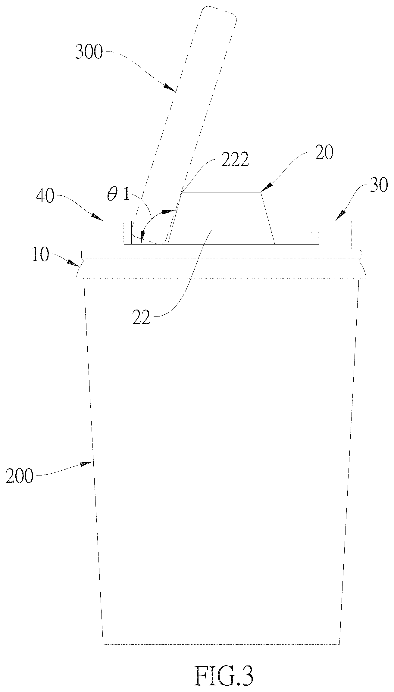
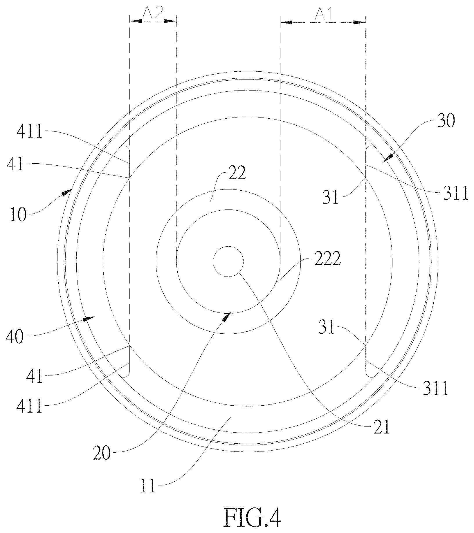
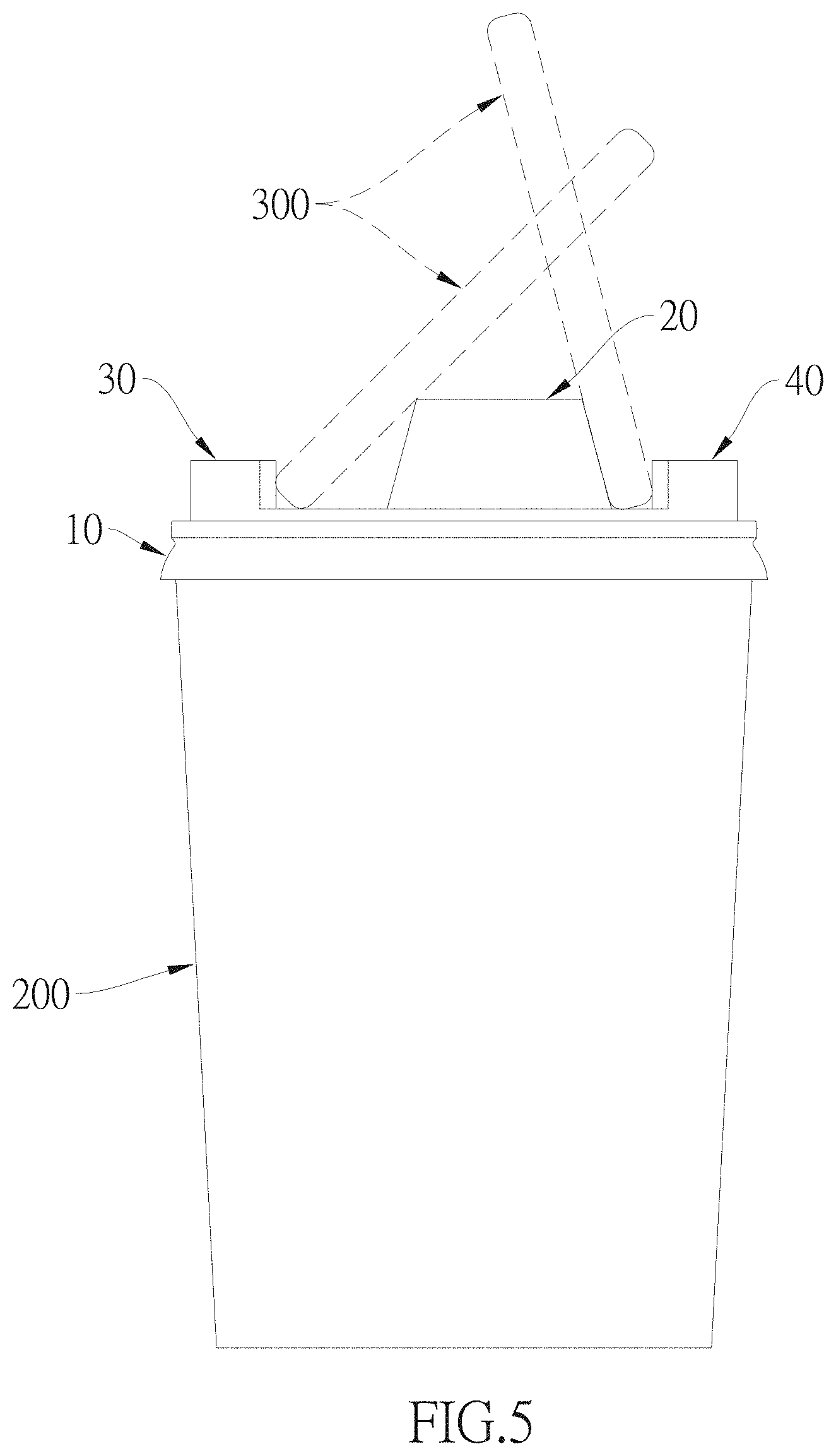
[0045] Referring to FIG. 4 to FIG. 5, which are a top view of a cup lid and a side view of the cup lid on a cup according to a second embodiment of the present disclosure. In the second embodiment, the spout section 20 is a cone with a planar top surface. The first leaning seat 30 and the second leaning seat 40 are arc-shaped with identical size, and are all disposed on the main body 10. The first leaning seat 30 and the second leaning seat 40 are formed on the circumferential skirt 11 and spaced away from each other. The spout section 20 is disposed on a non-central position of an inner region surrounded by the first leaning seat 30 and the second leaning seat 40. In addition, the spout section 20 is close to the second leaning seat 40, so that a length of the first clamping interval A1 is larger than a length of the second clamping interval A2. Accordingly, the communication device 300 can be propped up in different inclination angle, when the communication device 300 is respectively disposed in the first clamping interval A1 and the second clamping interval A2. For example, the communication device 300 is suitable for being watched, when the communication device 300 is disposed in the first clamping interval A1; or the communication device 300 is suitable for selfie photographing or video calling, when the communication device 300 is disposed in the second clamping interval A2. The cup lid of this embodiment can result in two different inclination angles, so that it increases the functionality of the cup lid and the additional value of the cup lid.
Third Embodiment
[0046] Referring to FIG. 6 and FIG. 7, which are a perspective view and a top view of the cup lid according to a third embodiment of the present disclosure. In the third embodiment, the spout section 20 is a cone with a planner top surface. The main body 10 has three arc-shaped leaning seats with identical size, which are the first leaning seat 30, the second leaning seat 40 and a third leaning seat 50. The third leaning seat 50 is protrudedly disposed on the top surface of the main body 10. Two ends of the third leaning seat 50 respectively have a third leaning end 51. The two third leaning ends 51 are aligned in a third leaning line L3. A third clamping interval A3 is formed between the third leaning line L3 and the supporting portion 22. The first leaning seat 30, the second leaning seat 40 and the third leaning seat 50 are arranged annularly in an equidistant manner. The two third leaning ends 51 of the third leaning seat 50 are respectively formed with a third chamfer surface 511, and an acute angle is formed between the third chamfer surface 511 and an inner edge of the circumferential skirt 11. The spout section 20 is disposed at a central position of a region surrounded by the first leaning seat 30, the second leaning seat 40 and the third leaning seat 50. A length of the first clamping interval A1, a length of the second clamping interval A2, and a length of the third clamping interval A3 are identical. The main body 10, the spout section 20, the first leaning seat 30, the second leaning seat 40 and the third leaning seat 50 are integrally formed in on piece. In this embodiment, the cup lid allows a user to dispose a smartphone in a propped-up state in three different directions without rotating the cup lid or cup, so as to selectively show another two users the screen of the smartphone.
Fourth Embodiment
[0047] Referring to FIG. 8, which is a top view of a cup lid according to a fourth embodiment of the present disclosure. In the fourth embodiment, the first leaning seat 30, the second leaning seat 40 and the third leaning seat 50 have different arc lengths, so that the first leaning seat 30, the second leaning seat 40 and the third leaning seat 50 are distributed in a ring in an equidistant manner or in an un-equidistant manner. Between the supporting portion 22 of the spout section 20 and the first leaning seat 30, the second leaning seat 40, and the third leaning seat 50 respectively forms the first clamping interval A1, the second clamping interval A2 and the third clamping interval A3 of different lengths. A length of the first clamping interval A1 is larger than a length of the second clamping interval A2. The length of the second clamping interval A2 is larger than a length of the third clamping interval A3. The cup lid of this embodiment allows a user to dispose the communication device 300 in the first clamping interval A1, the second clamping interval A2, or the third clamping interval A3 in three different inclination angles, respectively. Therefore, it increases the functionalities and the additional value of the cup lid. A special explanation is that, the third clamping interval A3 is formed between the third leaning line L3 and the outer periphery 222.
Fifth Embodiment
[0048] Referring to FIG. 9, which is a perspective view of the cup lid according to a fifth embodiment of the present disclosure. In the fifth embodiment, the spout section 20 is a polygon pyramid having a plurality of slanted lateral surfaces 221. The main body 10 has three arc-shaped leaning seats of identical size, which are the first leaning seat 30, the second leaning seat 40 and the third leaning seat 50. The first leaning seat 30, the second leaning seat 40 and the third leaning seat 50 are arranged annularly in an equidistant manner. The spout section 20 is disposed in a central position of a region surrounded by the first leaning seat 30, the second leaning seat 40 and the third leaning seat 50. The first leaning seat 30, the second leaning seat 40 and the third leaning seat 50 respectively face one of the slanted lateral surfaces 221. In addition, the slanted lateral surfaces 221 have different inclinations, so as to form different lengths of the first clamping interval A1, the second clamping interval A2 and the third clamping interval A3, respectively, between the spout section 20 and the first leaning seat 30, the second leaning seat 40, and the third leaning seat 50. Accordingly, the smartphone can be propped up in three different inclination angles. It therefore increases the functionalities and the additional value of the cup lid.
[0049] In conclusion, the cup lid of the present disclosure has the spout section and a plurality of leaning seats which are formed on the top wall of the main body and spacing away from each other, and forms a plurality of clamping intervals between the spout section and the leaning seats for retaining a communication device in a propped-up state, so as to shown a user the screen of the communication device. In addition, the present disclosure can provide different clamping intervals between the spout section and the leaning seats, respectively, so as to retain the mobile phone in different propped-up angles, to increase the convenience of use.
[0050] The foregoing description of the exemplary embodiments of the disclosure has been presented only for the purposes of illustration and description and is not intended to be exhaustive or to limit the disclosure to the precise forms disclosed. Many modifications and variations are possible in light of the above teaching.
[0051] The embodiments were chosen and described in order to explain the principles of the disclosure and their practical application so as to enable others skilled in the art to utilize the disclosure and various embodiments and with various modifications as are suited to the particular use contemplated. Alternative embodiments will become apparent to those skilled in the art to which the present disclosure pertains without departing from its spirit and scope.
* * * * *
D00000
D00001
D00002
D00003
D00004
D00005
D00006
D00007
D00008
D00009
XML
uspto.report is an independent third-party trademark research tool that is not affiliated, endorsed, or sponsored by the United States Patent and Trademark Office (USPTO) or any other governmental organization. The information provided by uspto.report is based on publicly available data at the time of writing and is intended for informational purposes only.
While we strive to provide accurate and up-to-date information, we do not guarantee the accuracy, completeness, reliability, or suitability of the information displayed on this site. The use of this site is at your own risk. Any reliance you place on such information is therefore strictly at your own risk.
All official trademark data, including owner information, should be verified by visiting the official USPTO website at www.uspto.gov. This site is not intended to replace professional legal advice and should not be used as a substitute for consulting with a legal professional who is knowledgeable about trademark law.