Drawn Cup-type Heat Exchanger
OKUBO; Atsushi ; et al.
U.S. patent application number 16/488160 was filed with the patent office on 2020-01-30 for drawn cup-type heat exchanger. The applicant listed for this patent is T.RAD Co., Ltd.. Invention is credited to Atsushi OKUBO, Taiji SAKAI.
| Application Number | 20200033065 16/488160 |
| Document ID | / |
| Family ID | 63370128 |
| Filed Date | 2020-01-30 |


| United States Patent Application | 20200033065 |
| Kind Code | A1 |
| OKUBO; Atsushi ; et al. | January 30, 2020 |
DRAWN CUP-TYPE HEAT EXCHANGER
Abstract
A structure of a drawn cup-type heat exchanger of improved pressure tightness is provided. A drawn cup-type heat exchanger is configured by stacking in plural number a long and thin tube element containing an inner fin inside a pair of cup plates. The cup plates have a flat containing portion containing the inner fin and a pair of cup portions communicating with both end portions of the containing portion; a circulation hole for communicating fluid into each of tube elements to be stacked is formed in the cup portions; and, to position both end portions in a longitudinal direction of the inner fin to be contained in front of the circulation hole of the cup portions, a corner portion is formed at at least one end portion in a width direction at both extremities in a longitudinal direction of the containing portion.
| Inventors: | OKUBO; Atsushi; (Tokyo, JP) ; SAKAI; Taiji; (Tokyo, JP) | ||||||||||
| Applicant: |
|
||||||||||
|---|---|---|---|---|---|---|---|---|---|---|---|
| Family ID: | 63370128 | ||||||||||
| Appl. No.: | 16/488160 | ||||||||||
| Filed: | February 28, 2018 | ||||||||||
| PCT Filed: | February 28, 2018 | ||||||||||
| PCT NO: | PCT/JP2018/008878 | ||||||||||
| 371 Date: | August 22, 2019 |
| Current U.S. Class: | 1/1 |
| Current CPC Class: | F28D 2021/0089 20130101; F28F 9/00 20130101; F28D 9/00 20130101; F28D 9/0043 20130101; F28F 3/025 20130101; F28F 2225/08 20130101; F28F 3/06 20130101; F28F 3/08 20130101; F28F 2275/04 20130101; F28F 21/084 20130101; F28F 3/027 20130101 |
| International Class: | F28D 9/00 20060101 F28D009/00; F28F 3/06 20060101 F28F003/06 |
Foreign Application Data
| Date | Code | Application Number |
|---|---|---|
| Mar 3, 2017 | JP | 2017-040870 |
Claims
1. A drawn cup-type heat exchanger configured by stacking in plural number a long and thin tube element containing an inner fin inside a pair of cup plates, wherein the cup plates have a fiat containing portion containing the inner fin and a pair of cup portions communicating with both end portions of the containing portion; a circulation hole for communicating fluid into each of tube elements to be stacked is formed in the cup portions; and, to position both end portions in a longitudinal direction of the inner fin to be contained in the containing portion in front of the circulation hole of the cup portions, a corner portion is formed at at least one end portion in a width direction at both extremities in a longitudinal direction of the containing portion.
2. The heat exchanger according to claim 1, wherein the corner portion is configured so that inner fin can be positioned in a state where an end portion thereof projects into an inside of the cup portion.
3. The heat exchanger according to claim 2, wherein cup portions in the pair of cup plates facing each other are joined in a state where side faces of circulation holes along a circulation direction in respective cup portions overlap each other.
4. The heat exchanger according to claim 3, wherein an end portion of the side face of the cup plate lying on the inside in the overlap does not project, exceeding a height of the inner fin, into the other cup plate side in a state where the pair of cup plates and the inner fin have been combined.
5. The heat exchanger according to claim 4, wherein a step portion is formed on the side face of the cup plate lying on the outside in the overlap and an end portion of the side face rising from the step portion is expanded outward, and joining has been performed in a state where an end portion of the side face of the cup plate lying on the inside in the overlap is in contact with a bottom surface of at least a part of the step portions.
6. The heat exchanger according to claim 1, wherein cup portions in the pair of cup plates facing each other are joined in a state where side faces of circulation holes along a circulation direction in respective cup portions overlap each other.
7. The heat exchanger according to claim 6, wherein an end portion of the side face of the cup plate lying on the inside in the overlap does not project, exceeding a height of the inner fin, into the other cup plate side in a state where the pair of cup plates and the inner fin have been combined.
8. The heat exchanger according to claim 7, wherein a step portion is formed on the side face of the cup plate lying on the outside in the overlap and an end portion of the side face rising from the step portion is expanded outward, and joining has been performed in a state where an end portion of the side face of the cup plate lying on the inside in the overlap is in contact with a bottom surface of at least a part of the step portions.
Description
TECHNICAL FIELD
[0001] The present invention relates to a drawn cup-type heat exchanger configured by stacking in plural number a tube element containing an inner fin inside a pair of cup plates.
BACKGROUND ART
[0002] Heat exchangers such as an oil cooler is utilized, for example, when an engine oil of an automobile is cooled with cooling water. As a heat exchanger, a heat exchanger of a drawn cup-type, which is configured by stacking in plural number a tube element containing an inner fin inside a pair of cup plates, is employed in many cases.
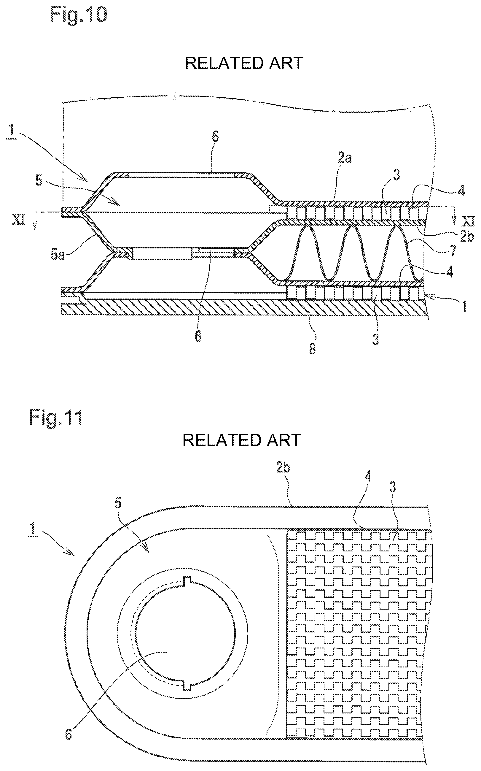
[0003] In FIG. 10, FIG. 11, there is shown an example of conventional usual tube element for use in a heat exchanger of a drawn cup-type. FIG. 10 illustrates a partial cross-sectional view showing a part of the tube element, and FIG. 11 illustrates a XI-XI arrow-seen plan view in FIG. 10.
[0004] In FIG. 10, FIG. 11, a long and thin tube element 1 is formed by brazing and joining rims of a pair of cup plates 2a, 2b that are disposed facing each other, and, in the internal space thereof, an inner fin 3 of an offset-type is contained. These cup plates 2a, 2b have a flat, long and thin containing portion 4 that contains the inner fin 3, and a cup portion 5 at both end portions of the containing portion 4. For the cup portion 5, a circulation hole 6 for causing fluid to communicate into each of the stacked tube elements 1 is formed.
[0005] Plural tube elements 1 are joined each other in a stacked state to form a core portion of the heat exchanger.
[0006] In FIG. 10, there is exemplified only the tube element 1 on the lowermost layer and a second tube element 1 stacked on the upper portion thereof. A third one and later are sequentially stacked in the same way in a range shown by a dashed one-dotted line, and furthermore an outer fin 7 is arranged between respective tube elements 1. Note that the tube element 1 on the lowermost layer is formed with the cup plate 2a on the upper side and with a bottom plate 8 on the lower side.
[0007] At both end portions in the longitudinal direction of the containing portion 4 of each of cup plates 2a, 2b, a pair of rectangular-circular cup portions 5 communicating in the stack direction are formed, and as shown in FIG. 10 the peripheral part thereof is raised by one step to form a step portion 5a. At the periphery of the step portion 5a, a small flange portion for joining, which extends horizontally and is even, is formed.
SUMMARY OF INVENTION
Technical Problem
[0008] In a case where stacked plural tube elements 1 are joined each other by brazing or the like to form a core portion of a heat exchanger, each of cup plates 2a, 2b, an inner fin 3 and an outer fin 7 are also joined at the same time. By joining the inner fin 3, whose entire shape in a plane is flat, with an internal surface of containing portions 4 of cup plates 2a, 2b, the upper surface thereof and the lower surface thereof facing each other, the whole of the tube element 1 is reinforced and pressure resistance strength is secured. For that purpose, it is necessary that each of these parts are arranged at predetermined mutual relative positions and are entirely joined while keeping the arranged state.
[0009] However, slight displacement often occurs in a temporary assembling process or a joining process. Displacement that occurs when the inner fin 3 is joined, in particular, affects the performance of an exchanger and largely affects the compressive strength thereof.
[0010] Therefore, until now, to prevent displacement of the inner fin 3 to be set to the cup plates 2a, 2b, a method is employed in which a dowel to be an obstacle for preventing movement is set up on a cup 5 side of the containing portion 4 in the cup plates 2a, 2b so that movement of the inner fin 3 toward a cup portion 5 side is prevented with the dowel.
[0011] However, the dowel position is at an inner side of the extremity in the longitudinal direction of the containing portion 4 and, on a side nearer to the extremity, there is no joining between an inner surface of the containing portion 4 and the upper/lower surface of the inner fin 3, and the strength of the entire tube element 1 is reduced and the pressure resistance strength is reduced.
[0012] In other words, the presence of this unjoined part increases the amount of change in shape relative to inner pressure and, since stress concentrates to the dowel fixed to the cup plates 2a, 2b, it is difficult to secure pressure resistance strength, particularly, in a heat exchanger for which a high specification about pressure proof is demanded.
[0013] To avoid this problem, one possible solution is to make the thickness of the cup plates 2a, 2b and/or the outer fin 7 larger, but this will bring about other problems such as weight increase and cost increase.
[0014] To join the cup plates 2a, 2b each other, if a small flange portion is formed on a periphery of the cup plate, in a case where the requirement is to secure the opening area of a circulation hole, the whole of a heat exchanger increases in size by the small flange portion. On the other hand, in a case where the requirement is to avoid the increase in size, the opening area of the circulation hole decreases by the small flange portion to increase circulation resistance to fluid.
[0015] Consequently, the present invention aims at providing a new heat exchanger with which these problems have been solved.
Solution to Problem
[0016] A first invention of the present inventions is a drawn cup-type heat exchanger configured by stacking in plural number a long and thin tube element containing an inner fin inside a pair of cup plates, in which the cup plates have a flat containing portion containing the inner fin and a pair of cup portions provided at both end portions of the containing portion; a circulation hole for communicating fluid into each of tube elements to be stacked is formed in the cup portions; and, to position both end portions of the inner fin to be contained in front of the circulation hole of the cup portions, a corner portion is formed at least one end portion in a width direction at both extremities in a longitudinal direction of the containing portion (claim 1).
[0017] In a second invention of the present inventions, in the first invention, the corner portion is configured so that the inner fin can be positioned in a state where an end portion thereof projects into an inside of the cup portion (claim 2).
[0018] In a third invention of the present inventions, in the first invention or in the second invention, cup portions in the pair of cup plates facing each other are joined in a state where side faces of circulation holes along a circulation direction in respective cup portions overlap each other (claim 3).
[0019] In a fourth invention of the present inventions, in the third invention, an end portion of a side face of the cup plate 2a lying on the inside in the overlap does not project, exceeding a height of the inner fin, into the other cup plate 2b side in a state where the pair of cup plates 2a, 2b and the inner fin have been combined (claim 4).
[0020] In a fifth invention of the present inventions, in the fourth invention, a step portion is formed on the side face of the cup plate lying on the outside in the overlap and an end portion of the side face rising from the step portion is expanded outward, and joining has been performed in a state where an end portion of the side face of the cup plate lying on the inside in the overlap is in contact with a bottom surface of at least a part of the step portions (claim 5).
Advantageous Effects of Invention
[0021] In the first invention, a corner portion 9 is formed, to position both end portions of an inner fin to be contained in a containing portion in front of circulation holes of the cup portion 5 of cup plates 2a, 2b, at at least one end portion in a width direction at both extremities in a longitudinal direction of the containing portion. As a consequence of this configuration, it is unnecessary to provide an obstacle such as a dowel inside the containing portion 4, and, by matching both end portions of the inner fin 3 with the corner portions 9 lying at the extremities of the containing portion 4, the inner fin 3 and the cup plates 2a, 2b can be positioned each other. Consequently, since parts not joined with the inner fin in a cup plate decrease, pressure tightness of the tube element 1 is improved and reduction in thickness of respective parts configuring the tube element 1 is possible.
[0022] In the second invention, the extremity of the inner fin 3 is projected into the inside of the cup portion 5 in a state where the end portion of an inner fin is abutted on the corner portion of the cup plates 2a, 2b. As a consequence of the configuration, a joining portion between the cup plates 2a, 2b and the inner fin 3 is broadened to improve the joining strength, and pressure tightness can be secured more certainly.
[0023] In the third invention, the joining between the cup portions 5 in a pair of cup plates 2a, 2b facing each other is performed in a state where a side face 10 along a circulation direction of the circulation hole in respective cup portions 5 overlap each other. As a consequence of this configuration, the small flange portion is unnecessary and, therefore, the opening area of the circulation hole can be secured without increasing the size of a heat exchanger.
[0024] In the fourth invention, the end portion of the side face 10 of the cup plate 2a lying on the inside in the overlap does not project into the other cup plate 2b side exceeding the height of the inner fin 3. As a consequence of this configuration, it is possible to conform the end face of the side face 10 of the cup plate 2a to the end face of the side face 10 of the containing portion 4 to make these uniform on an approximately the same plane over the entire circumference of the cup plate 2a to thereby improve molding processability and a material yield by press processing of the cup plate 2a.
[0025] In the fifth invention, a step portion is formed on the side face of the cup plate lying on the outside in the overlap and the end portion of a side face rising from the step portion is expanded outward, and joining has been performed in a state where an end portion of the side face of the cup plate lying on the inside in the overlap is in contact with a bottom surface of at least a part of the step portions. As a consequence of this expansion, the part functions as a guide when both cup plates are made to fit and the fitting is easy to improve workability. Moreover, by configuring so that joining such as brazing is performed in a state where the end portion of the other cup plate is in contact with the bottom surface of at least a part of step portions 11, even when a compressive load is applied in the stacking direction of respective cup plates 2a, 2b in a joining process, the load is supported with the step portion 11 to join soundly and airtightly the cup plates 2a, 2b paired vertically without generating displacement and/or deformation of the fitting portion.
BRIEF DESCRIPTION OF DRAWINGS
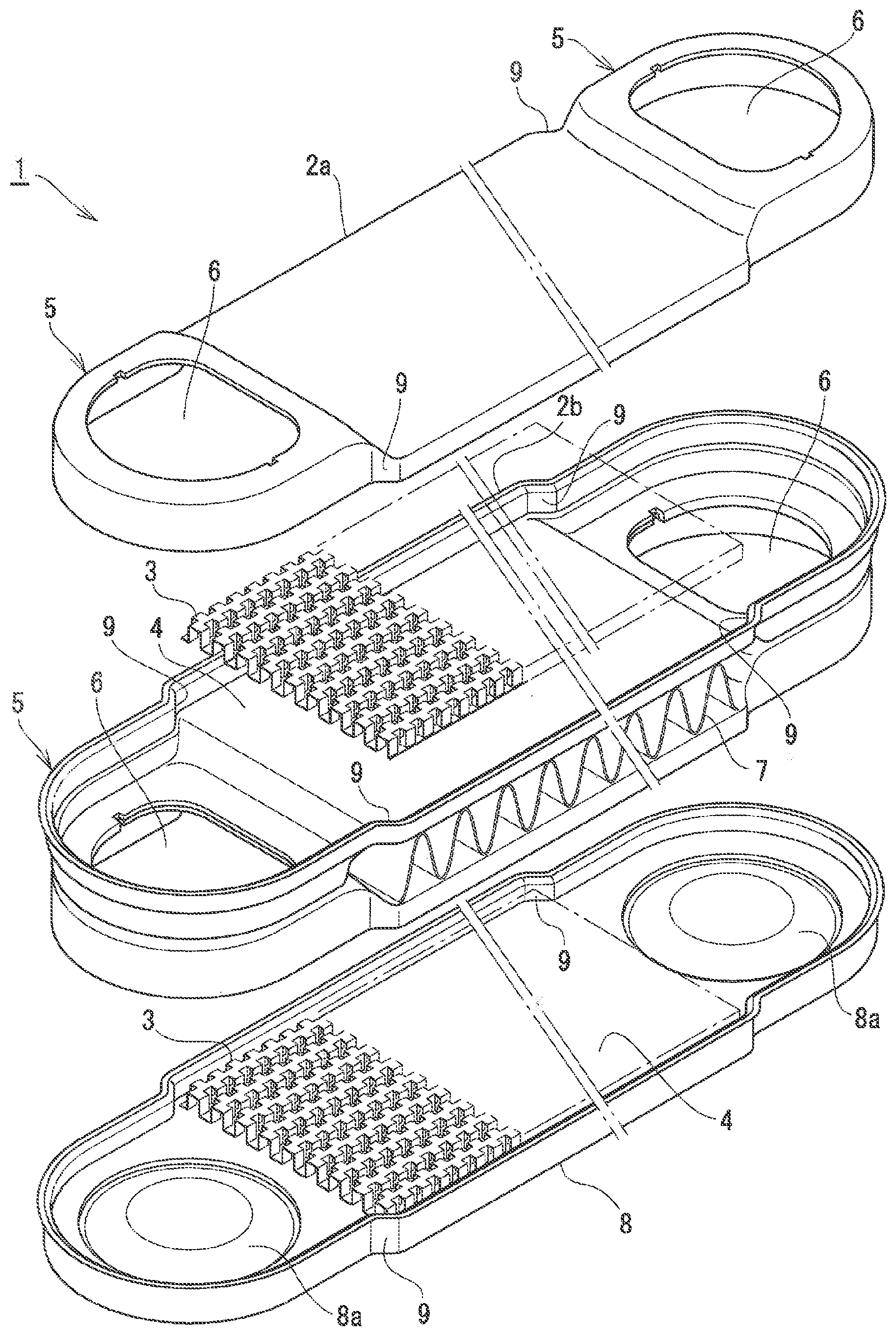
[0026] FIG. 1 illustrates a partially exploded perspective view showing in an exploded state a part of plural tube elements to be stacked, in an embodiment of the heat exchanger of the present invention.
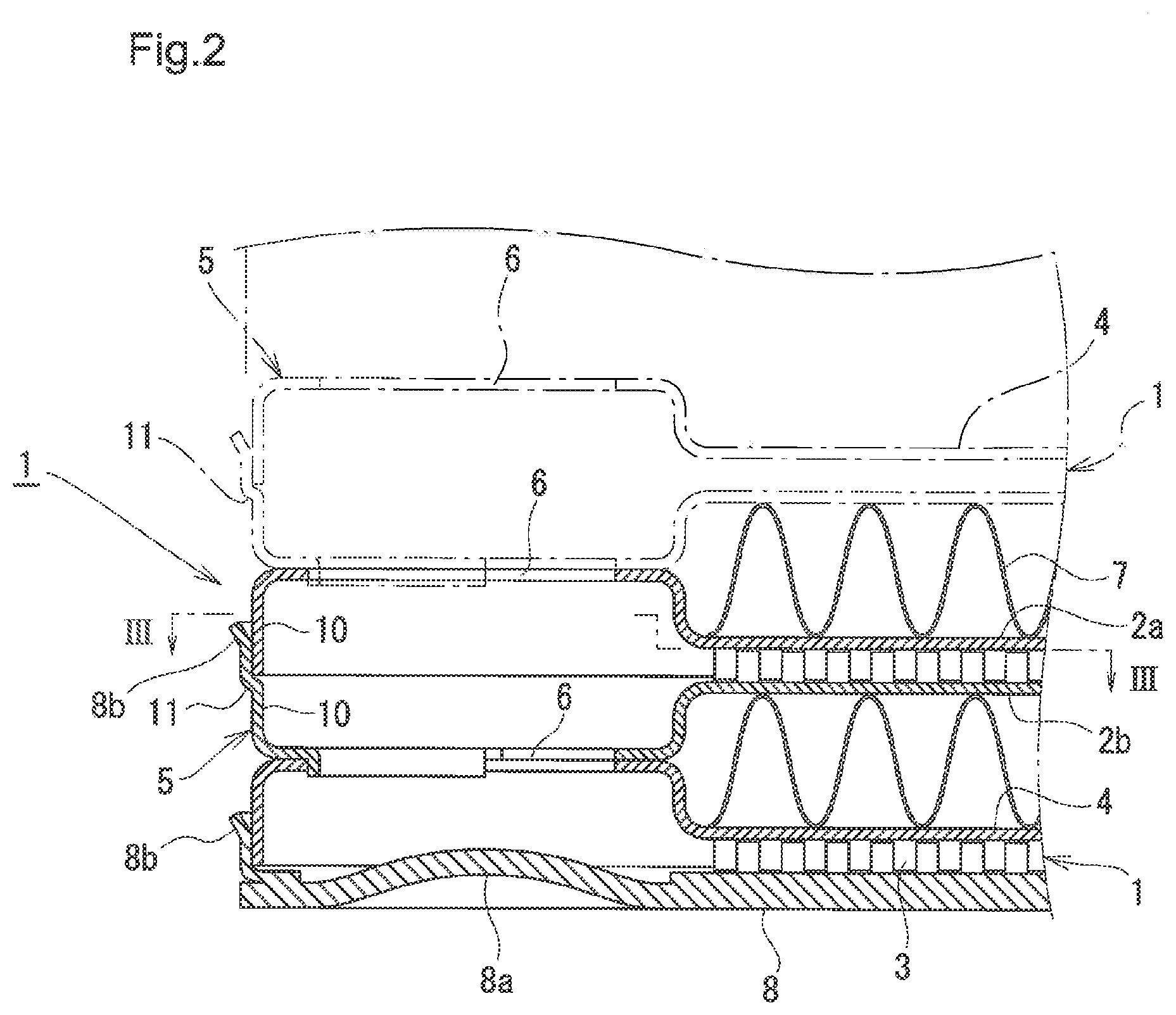
[0027] FIG. 2 illustrates a partial side cross-sectional view showing a state where respective tube elements in FIG. 1 are stacked each other.
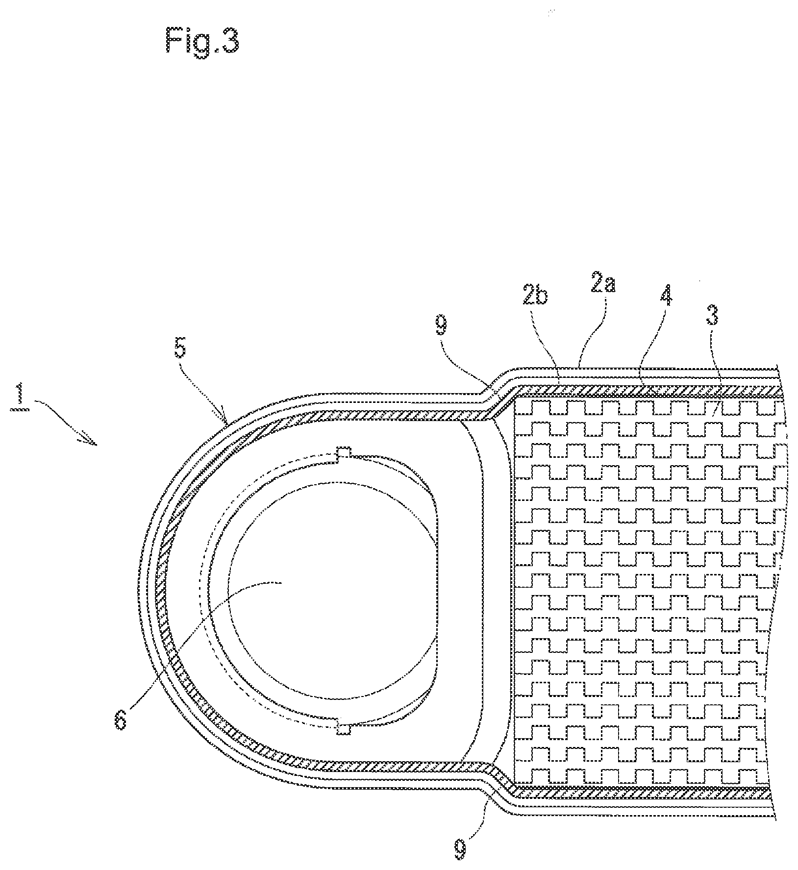
[0028] FIG. 3 illustrates a plan cross-sectional view seen along a arrow in FIG. 2.
[0029] FIG. 4 illustrates a partial side cross-sectional view showing a state where respective tube elements are stacked each other, which is a second embodiment of the heat exchanger of the present invention.
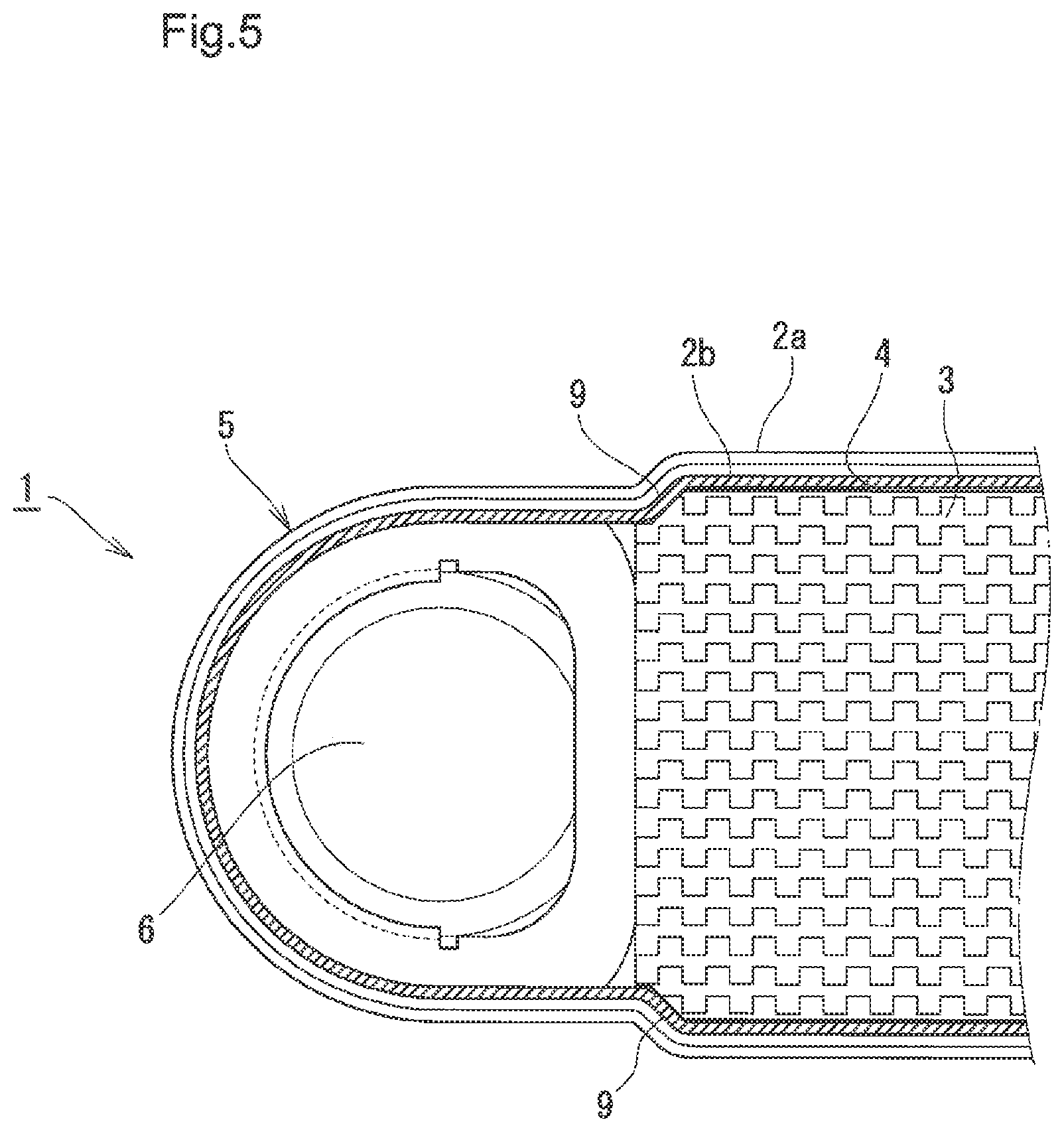
[0030] FIG. 5 illustrates a plan cross-sectional view seen along a V-V arrow in FIG. 4.
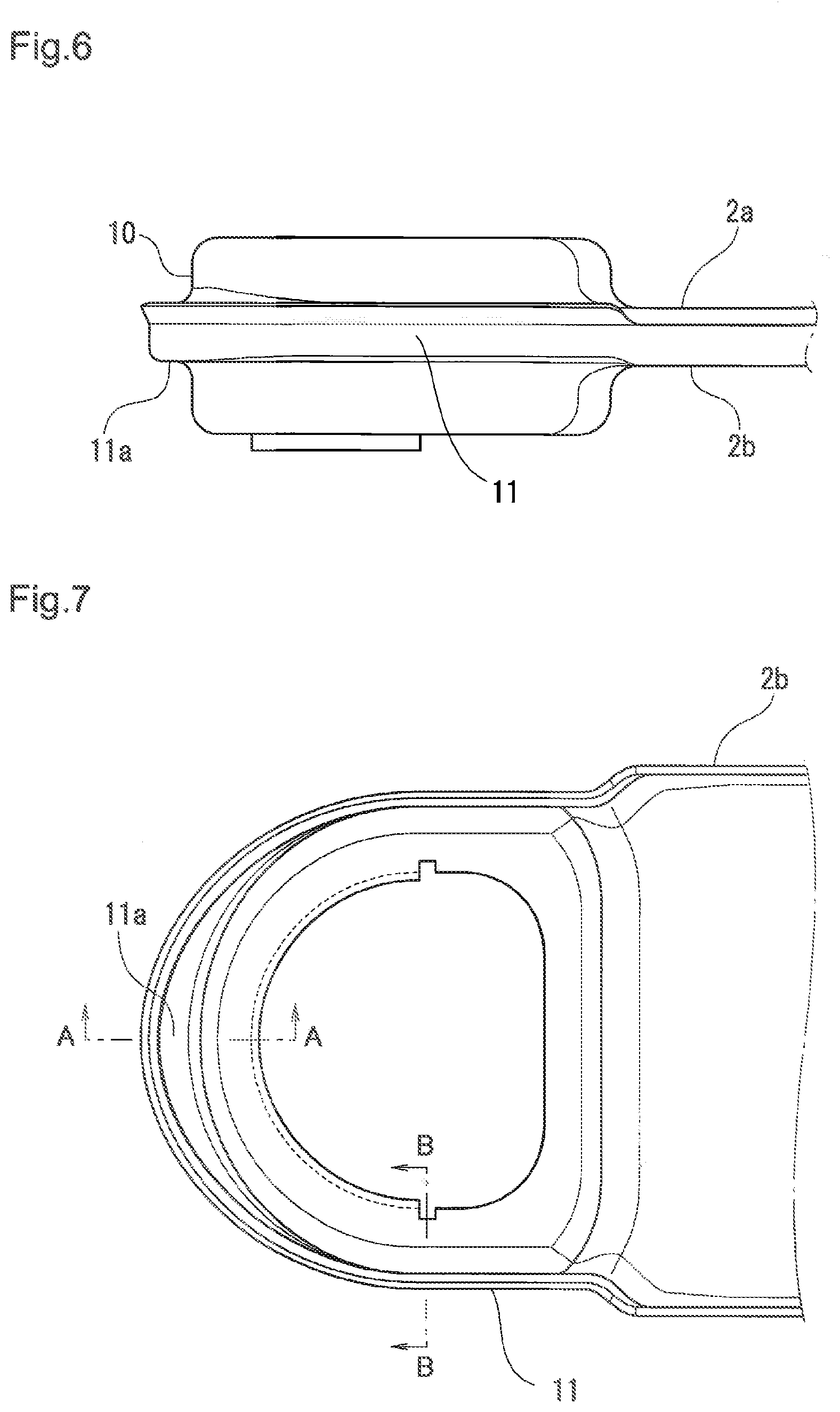
[0031] FIG. 6 illustrates a partial side view showing a third embodiment of the present invention.
[0032] FIG. 7 illustrates a plan view of the same.
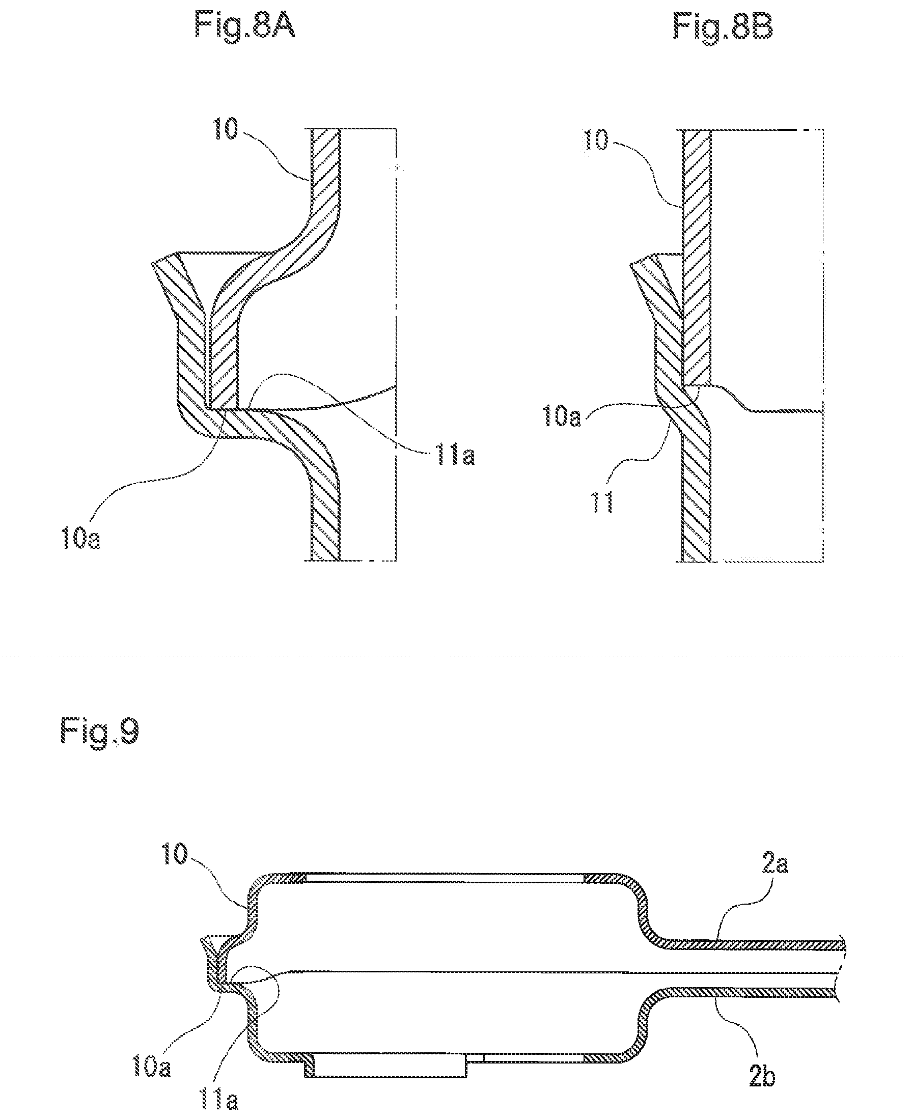
[0033] FIG. 8 illustrates a principal part-enlarged cross-sectional view of the same.
[0034] FIG. 9 illustrates a principal part cross-sectional view of the same.
[0035] FIG. 10 illustrates a partial side cross-sectional view showing a state where respective tube elements are stacked each other in a conventional heat exchanger.
[0036] FIG. 11 illustrates a plan cross-sectional view seen along a VII-VII arrow in FIG. 10.
DESCRIPTION OF EMBODIMENTS
[0037] Next, an embodiment of a tube element that is a component of the heat exchanger of the present invention will be explained on the basis of the drawings. FIG. 1 illustrates a partially exploded perspective view showing in an exploded state a part of plural tube elements to be stacked, and FIG. 2, FIG. 3 illustrate a state where the tube elements 1 in FIG. 1 are stacked. Meanwhile, in a case where respective members in each drawing in embodiments of the present invention are approximately the same as respective members in above-described FIG. 10, FIG. 11, the same symbols as those in FIG. 10, FIG. 11 are given and duplicated explanations will be omitted as far as possible.
[0038] In FIG. 1, the tube element 1 is configured of an upper side cup plate 2a and a lower side cup plate 2b, each of which is long and thin, and an inner fin 3 interposed between both cup plates 2a, 2b. Then, an outer peripheral edge of the cup plate 2a on the upper side is fitted to an inner peripheral of the cup plate 2b on the lower side. The peripheral edge of the cup plate 2b on the lower side is formed with a step and the outer peripheral edge of the peripheral edge expands outward, an expanding portion 8b guiding smoothly an edge portion of the cup plate 2a on the upper side. Furthermore, an outer fin 7 is arranged between respective tube elements 1 stacked vertically. Meanwhile, what is shown on the lowermost side is a bottom plate 8, which has the same planar shape as that of the cup plate 2b on the lower side. In this example, on a bottom surface of cup portions at both ends in the longitudinal direction of this bottom plate 8, a circular convex portion 8a is formed toward the upper direction in the stacking direction, but the circular convex portion 8a may be omitted. The cup plates 2a, 2b, the inner fin 3 and the outer fin 7 have metallic quality of material such as aluminum alloy or stainless steel, and, as to the shape of the inner fin 3, known fins such as an offset fin can be used.
[0039] In a state where a pair of cup plates 2a, 2b are arranged vertically while facing each other, a containing portion 4 having a square shape in plan view is formed at the central portion in the longitudinal direction of these, and at both end portions in the longitudinal direction thereof, a cup portion 5, which has a flat cup-like shape with a rectangular-circular planar shape and a height higher than the containing portion 4, is formed. The inner fin 3 is arranged inside the containing portion 4 of the cup plates 2a, 2b. Furthermore in the bottom of the cup portion 5, a circulation hole 6 in an approximately circular shape for circulating fluid in the stacking direction is formed. Note that the circulation hole 6 is formed coaxially for each of a vertical pair of the cup plates 2a, 2b.
[0040] The width of the containing portion 4 of the cup plates 2a, 2b is formed slightly larger than the width of the cup portions 5 communicating with both end portions thereof. Then corner portions 9 are formed in four portions at the boundary between both end portions in the longitudinal direction of the containing portion 4 and the rectangular portion of the rectangular-circular portion of the cup portion 5. In this embodiment, each of the corner portions 9 inclines relative to the longitudinal direction of the cup plates 2a, 2b, but the corner portion 9 may be formed orthogonally instead of the inclination.
[0041] As shown in FIG. 3, both portions in the width direction of extremities in the longitudinal direction of the inner fin 3 is positioned in a state of being in contact with a pair of corner portions 9 of the containing portion 4.
[0042] As shown in FIG. 2, the cup portions 5 facing each other are in a state where the side faces 10 along the circulation direction of the circulation hole 6 in respective cup portions 5 overlap each other. In the drawing, a step portion 11 is formed outward on the side face 10 of the cup portion 5 on the lower side, and the end portion of the side face 10 rising from the step portion 11 is expanded outward to form there the expanding portion 8b. Moreover, the end portion of the side face 10 of the cup plate 2a lying on the inside in the overlap does not project into the other cup plate 2b side exceeding the height of the inner fin 3. Note that, in FIG. 1, these step portions 11 and outward expansion of the end portion of the side face 10 are omitted for the purpose of avoiding complication of the drawing.
[0043] As a consequence of forming a state where the side faces 10 are overlapped each other as described above, the joining portion between the cup portions 5 is made to be small to configure a compact heat exchanger. Moreover, by expanding outward the end portion of the side face 10 to form the expanding portion 8b, it is possible to guide the edge portion of the side face 10 of the cup plate 2a on the upper side to the expanding portion 8b. Consequently, a fitting operation of the side faces 10 thereof is easy to improve the operating efficiency thereof.
[0044] Moreover, since the end portion of the side face 10 of the cup plate 2a does not project into the other cup plate 2b side exceeding the height of the inner fin 3, it is possible to make the end face of the side face 10 of the cup plate 2a even on an approximately the same plane over the entire circumference of the cup plate 2a, while making the same conform the end face of the side face 10 in the containing portion 4, to thereby improve molding processability by press processing and a material yield of the cup plate 2a.
[0045] In a state as positioned in FIG. 2, FIG. 3, each of members configuring the tube element 1, and the outer fin 7 etc. are joined integrally by brazing. In a case where a heat exchanger is configured of an aluminum material, a cladding material covered with a brazing material can be used as a plate.
[0046] FIG. 4, FIG. 5 illustrate, in accordance with FIG. 2, FIG. 3, a second embodiment of the tube element 1 in the heat exchanger of the present invention. A different point of this embodiment from the embodiment in FIG. 2, FIG. 3 is that both extremities in the longitudinal direction of the inner fin 3 contained in the containing portion 4 of the tube element 1 slightly project into the inside of the cup portion 5 from the containing portion 4, and the embodiment is formed while other points are in the same way as the above-described Example.
[0047] In this embodiment, a length in the longitudinal direction of the inner fin 3 is set to be slightly longer than the length in the longitudinal direction of the containing portion 4. Then as shown in FIG. 4, the extremity of the inner fin 3 projects into the inside of the cup portion 5 by the slightly longer amount. As a consequence of forming a fillet by brazing on the projecting part, joining areas between the cup plates 2a, 2b and the inner fin 3 increase more and stress concentration at the joining portion is relaxed to thereby improve pressure tightness more. As to the projecting amount, for example, in a case where an offset fin is used for the inner fin 3, several pitches or less of the offset pitch (dimension from a certain offset to the subsequent offset) suffice, and less than one pitch may be acceptable. The projecting part receives pressure of fluid, and therefore an excess projection causes snapping of the inner fin 3 at the part. Meanwhile, as another positioning method, four corners of the inner fin 3 may be formed in a shape conformed to the inclined face of the corner portions 9 of the cup plates 2a, 2b as shown in FIG. 5 to position the cup plates 2a, 2b and the inner fin 3 with both inclined faces.
[0048] Next, FIG. 6 illustrates a partial side view of a third embodiment of the present invention, FIG. 7 illustrates a plan view of the same, FIGS. 8(A), 8(B) illustrate a principal part-enlarged cross-sectional view of the same, and FIG. 9 illustrates a cross-sectional view along A-A in FIG. 7. Different points of this embodiment from the above-described embodiment are shapes of the step portion 11a and the side face 10 seated on it. In the A-A cross-sectional position in FIG. 7, the step portion 11a evaginates to the outside in a radius direction and is formed as in FIG. 8(A), on which a lower end face 10a of the side face 10 of the other cup plate is seated. In this case, the side face 10 evaginates outward so that the lower end face 10a thereof is aligned with the step portion 11a.
[0049] As a consequence of performing joining by brazing in a state where the lower end face 10a of the side face 10 of the other cup plate is in contact with the bottom of the step portion 11a as described above, even in a case where a compressive load is applied in the stacking direction of each of the cup plates 2a, 2b to secure the contact of these members in a joining process, the load is supported with the step portion 11a so as not to cause displacement or deformation in the fitting portion of the cup plates 2a, 2b that form vertically a pair with each other.
[0050] On the other hand, in the cross-sectional position of B-B in FIG. 7, the step portion 11 is formed, as in FIG. 8 (B), in the same shape as that in the embodiment in above-described FIG. 4.
[0051] As a consequence of forming the step portion 11a supporting the load only in a limited vicinity of the extremity in the longitudinal direction of the cup plate in this way, it is possible to make the evagination of the cup plate minimum and to secure sufficiently the opening area of the circulation hole, and a heat exchanger with a small size, low circulation resistance and good assemblability can be provided.
INDUSTRIAL APPLICABILITY
[0052] The present invention can be utilized for a heat exchanger of a drawn cup-type such as an oil cooler.
REFERENCE SIGNS LIST
[0053] 1: tube element
[0054] 2a: cup plate
[0055] 2b: cup plate
[0056] 3: inner fin
[0057] 4: containing portion
[0058] 5: cup portion
[0059] 5a: step portion
[0060] 6: circulation hole
[0061] 7: outer fin
[0062] 8: bottom plate
[0063] 8a: circular convex portion
[0064] 8b: expanding portion
[0065] 9: corner portion
[0066] 10: side face
[0067] 10a: lower end face
[0068] 11: step portion
[0069] 11a: step portion
* * * * *
D00000
D00001
D00002
D00003
D00004
D00005
D00006
D00007
D00008
XML
uspto.report is an independent third-party trademark research tool that is not affiliated, endorsed, or sponsored by the United States Patent and Trademark Office (USPTO) or any other governmental organization. The information provided by uspto.report is based on publicly available data at the time of writing and is intended for informational purposes only.
While we strive to provide accurate and up-to-date information, we do not guarantee the accuracy, completeness, reliability, or suitability of the information displayed on this site. The use of this site is at your own risk. Any reliance you place on such information is therefore strictly at your own risk.
All official trademark data, including owner information, should be verified by visiting the official USPTO website at www.uspto.gov. This site is not intended to replace professional legal advice and should not be used as a substitute for consulting with a legal professional who is knowledgeable about trademark law.