Method For Forming Plating
Sakamoto; Ichizo ; et al.
U.S. patent application number 16/490139 was filed with the patent office on 2020-01-09 for method for forming plating. This patent application is currently assigned to Omron Corporation. The applicant listed for this patent is Omron Corporation. Invention is credited to Yuhei Fujioka, Ichizo Sakamoto, Masafumi Suzuki.
| Application Number | 20200010971 16/490139 |
| Document ID | / |
| Family ID | 63522051 |
| Filed Date | 2020-01-09 |
| United States Patent Application | 20200010971 |
| Kind Code | A1 |
| Sakamoto; Ichizo ; et al. | January 9, 2020 |
METHOD FOR FORMING PLATING
Abstract
A plating is formed on one side of a cathode by applying a paste composed of particles mixed with a plating liquid to one side of the cathode, disposing a liquid holding member impregnated with the plating liquid on one side of an anode, opposing the cathode and the anode face, and then bringing the liquid holding member and the paste into contact with each other, and applying a voltage between the cathode and the anode.
| Inventors: | Sakamoto; Ichizo; (Kyoto, JP) ; Suzuki; Masafumi; (Kyoto, JP) ; Fujioka; Yuhei; (Kyoto, JP) | ||||||||||
| Applicant: |
|
||||||||||
|---|---|---|---|---|---|---|---|---|---|---|---|
| Assignee: | Omron Corporation Kyoto JP |
||||||||||
| Family ID: | 63522051 | ||||||||||
| Appl. No.: | 16/490139 | ||||||||||
| Filed: | December 13, 2017 | ||||||||||
| PCT Filed: | December 13, 2017 | ||||||||||
| PCT NO: | PCT/JP2017/044723 | ||||||||||
| 371 Date: | August 30, 2019 |
| Current U.S. Class: | 1/1 |
| Current CPC Class: | C25D 17/00 20130101; C25D 15/02 20130101; C25D 17/10 20130101; C25D 5/02 20130101 |
| International Class: | C25D 5/02 20060101 C25D005/02; C25D 15/02 20060101 C25D015/02; C25D 17/10 20060101 C25D017/10 |
Foreign Application Data
| Date | Code | Application Number |
|---|---|---|
| Mar 13, 2017 | JP | 2017-047763 |
Claims
1. A method for forming a plating, the method forming a plating on one side of a cathode by: applying, to the side of the cathode, a paste obtained by mixing particles with a plating liquid; disposing a liquid holding member impregnated with the plating liquid on one side of an anode; opposing the cathode and the anode, and then bringing the liquid holding member and the paste into contact with each other; and applying a voltage between the cathode and the anode, wherein the particles comprise either a metal or a resin.
2. The method according to claim 1, wherein the paste is mixed with a surfactant.
3. (canceled)
4. The method for forming a plating according to claim 1, wherein the particles have a particle size of 0.02 .mu.m or more and 0.6 .mu.m or less.
5. The method for forming a plating according to claim 1, wherein the particles are 10% by weight or more and 72% by weight or less with respect to the paste.
6. The method for forming a plating according to claim 1, wherein the liquid holding member is a sponge.
7. The method for forming a plating according to claim 2, wherein the particles have a particle size of 0.02 .mu.m or more and 0.6 .mu.m or less.
8. The method for forming a plating according to claim 2, wherein the particles are 10% by weight or more and 72% by weight or less with respect to the paste.
9. The method for forming a plating according to claim 4, wherein the particles are 10% by weight or more and 72% by weight or less with respect to the paste.
10. The method for forming a plating according to claim 2, wherein the liquid holding member is a sponge.
11. The method for forming a plating according to claim 4, wherein the liquid holding member is a sponge.
12. The method for forming a plating according to claim 5, wherein the liquid holding member is a sponge.
Description
TECHNICAL FIELD
[0001] The present disclosure relates to a method for forming a plating.
BACKGROUND ART
[0002] Patent Document 1 discloses a method for forming a plating, in such a way that for forming a plating film that has a fluorine resin film of 5 .mu.m or less in film thickness, on an electroless plating film or an electroless composite plating film, the fluorine resin film is formed with the use of a solution of fluorine resin particles dispersed in water with a cationic surfactant.
[0003] In addition, Patent Document 2 discloses a method for forming a plating, in such a way that with a cathode disposed at a vertically lower position in a plating tank, dispersed particles dispersed in a plating liquid are gradually precipitated toward the cathode, and deposited on the cathode.
PRIOR ART DOCUMENTS
Patent Documents
[0004] Patent Document 1: Japanese Unexamined Patent Publication No. 2007-39711
[0005] Patent Document 2: Japanese Unexamined Patent Publication No. 2016-141862
SUMMARY OF THE INVENTION
Problems to be Solved by the Invention
[0006] In the foregoing method for forming the plating, however, the base material or the electrode is immersed in the plating liquid contained in the plating tank in order to form the plating. For this reason, the method has the problem of large-scale and costly facility. In addition, it is necessary to maintain a large amount of plating liquid and treat the waste liquid, which also leads to an increase in cost.
[0007] In addition, in the latter method, the plating liquid may be stirred in order to replenish the plating metal consumed near the cathode, and the particles in the plating liquid will move, thereby making it difficult to form a high-concentration plating film. In addition, the configuration is significantly restricted, for example, the cathode has to be placed horizontally.
[0008] An object of the present disclosure is to provide a method for forming a plating, which is capable of forming a high-concentration plating film with a simple and inexpensive facility that uses a small amount of plating liquid.
Means for Solving the Problem
[0009] The present disclosure provides, as a means for solving the foregoing problems, a method for forming a plating, which forms a plating on one side of a cathode by:
[0010] applying, to the side of the cathode, a paste obtained by mixing particles with a plating liquid;
[0011] disposing a liquid holding member impregnated with the plating liquid on one side of an anode;
[0012] opposing the cathode and the anode, and then bringing the liquid holding member and the paste into contact with each other; and
[0013] applying a voltage between the cathode and the anode.
Effect of the Invention
[0014] According to the present disclosure, the liquid holding member is disposed on one side of the anode, and the paste is applied to one side of the cathode. Thus, a high-concentration plating film can be formed inexpensively without requiring a large-scale facility or a large amount of plating liquid.
BRIEF DESCRIPTION OF THE DRAWINGS
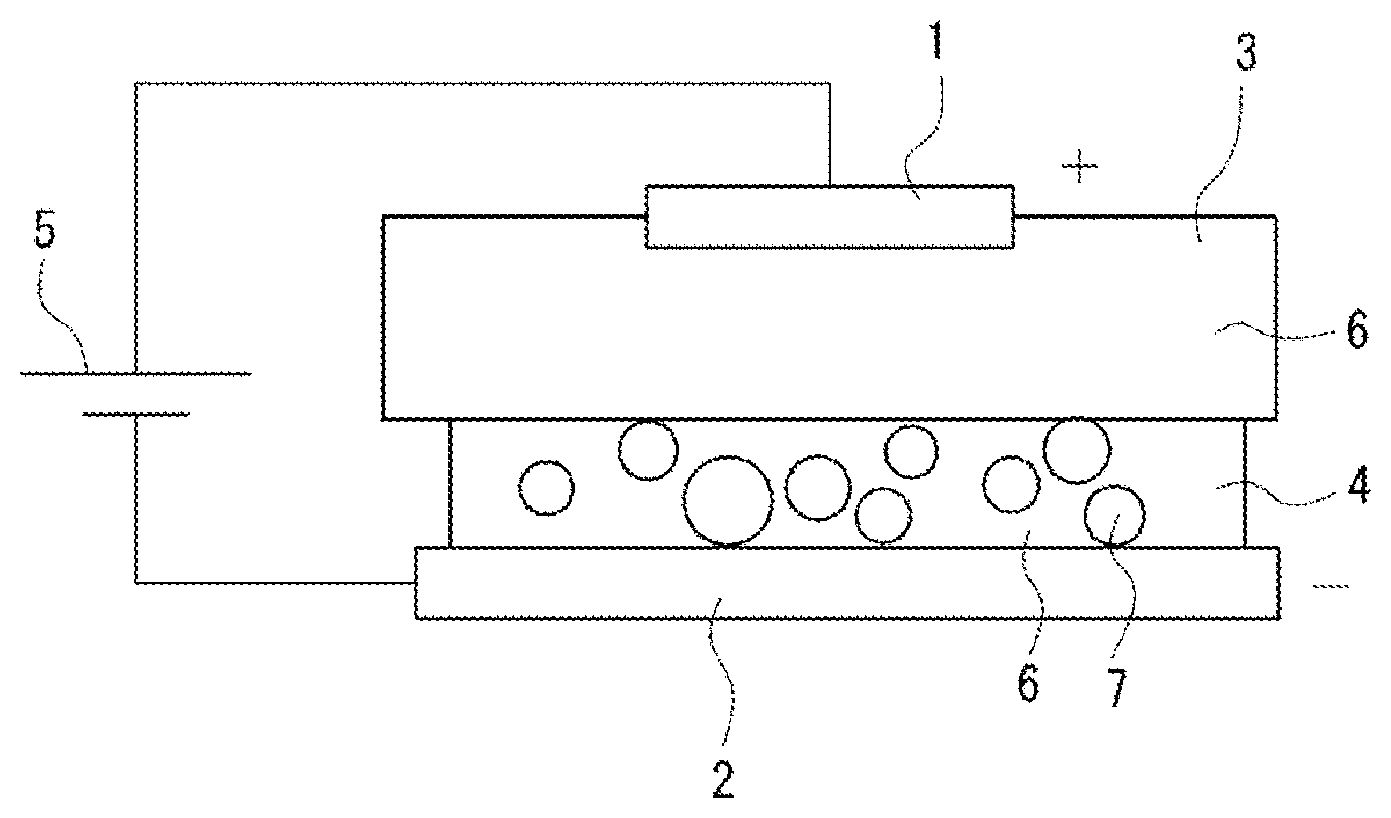
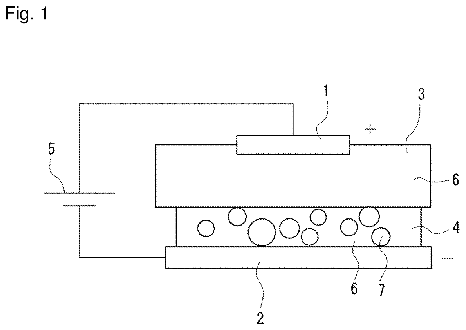
[0015] FIG. 1 is a schematic explanatory view of a plating forming device according to the embodiment.
MODE FOR CARRYING OUT THE INVENTION
[0016] Hereinafter, an embodiment according to the present disclosure will be described with reference to the accompanying drawing. It is to be noted that the following description is essentially considered by way of example only, and not to be considered intended to limit the present disclosure, applications thereof, or intended uses thereof. In addition, the drawing is considered schematic, and the ratios and the like between respective dimensions are different from actual ones.
[0017] FIG. 1 shows a plating forming device according to the embodiment. This plating forming device is configured such that a plate-shaped anode 1 and a plate-shaped cathode 2 are disposed to cause the plate surfaces to face each other, and a liquid holding member 3 impregnated with a plating liquid 6 is disposed on the surface of the anode 1 opposed to the cathode 2, a paste 4 is applied to the surface of the cathode 2 opposed to the anode to bring the liquid holding member 3 and the paste 4 into contact with each other.
[0018] For the anode 1, a flat plate made of a platinum insoluble anode is used. Although the insoluble anode 1 is used as the anode 1 herein, a soluble material such as Ag, Au, Pd, Rh, Ni, or Cr can also be used.
[0019] For the cathode 2, a flat plate made of a tough pitch copper (C1100) cathode is used. The surface area of one side (that is, the opposed surface) of the cathode 2 is larger than that of the anode 1.
[0020] A direct-current power supply 5 is connected between the anode 1 and the cathode 2.
[0021] A urethane sponge is used for the liquid holding member 3. The urethane sponge is flat in shape, has substantially the same area as the cathode 2, and is opposed to the cathode 2. In this case, the thickness of the liquid holding member 3 is adjusted to 10 mm or less. Thus, the current from the anode can be efficiently transmitted. The liquid holding member 3 is impregnated with a palladium-nickel plating liquid. However, the plating liquid 6 with which the member can be impregnated is not limited thereto, and various other plating liquids 6 such as an Ag plating liquid and an Au plating liquid can be used depending on the intended use.
[0022] For the paste 4, the plating liquid 6 mixed with particles 7 is used. More specifically, the paste 4 contains, as main components, the plating liquid 6 and the particles 7, which can be applied to the surface of the cathode 2 which is the object, maintains the applied shape even when a pressure is applied by a brush after the application, and has conductivity. For the plating liquid 6, the same liquid as that with which the liquid holding member 3 is impregnated can be used, and a palladium-nickel plating liquid is used herein. For the particles 7, a zinc oxide coated with silica is used. As for the particle sizes of the particles 7, the primary particle size is adjusted to 0.6 .mu.m or less. The particle sizes of the particles 7 are adjusted to 0.6 .mu.m or less in order to sufficiently increase the packing density of the particles in the plating film.
[0023] However, the particles 7 are not limited to the zinc oxide, and metal materials, synthetic resin materials such as fluorine resins, nylon, and polyethylene, graphite, and compounds such as graphite fluoride, molybdenum dioxide, and boron nitride may be used. In this case, for example, the use of a fluorine resin can impart wettability, in addition to the performance of conventional metal plating films.
[0024] In addition, the paste 4, the plating liquid 6, and the particles 7 are modified with a surfactant as a dispersion aid. Surfactants that can be used include a cationic surfactant, an amphoteric surfactant that exhibits a cationic property corresponding to the pH of the plating liquid 6, and a nonionic surfactant, for example. The use of the surfactant can improve the wettability of the plating surface, prevent plating defects such as non-plating and pits, and suppress the generation of mist from the plating liquid 6.
[0025] In the plating forming device configured as described previously, the liquid holding member 3 impregnated with the plating liquid 6 is disposed on one side (that is, the opposite surface) of the anode 1, and the paste 4 is applied to one surface (that is, the opposed surface) of the cathode 2. The paste 4 is applied by a dispenser, a squeegee or the like, and the thickness is adjusted to 0.1 mm to 0.5 mm. The current from the anode can be efficiently transmitted to the cathode 2 by setting the thickness of the paste 4 as just described.
[0026] Then, the anode 1 and the cathode 2 are disposed to be opposed to each other, and the liquid holding member 3 and the paste 4 are brought into surface contact with each other. In this case, the anode 1 and the cathode 2 may be opposed in the vertical direction, or may be opposed in other directions such as in the horizontal direction.
[0027] In this condition, the anode 1 and the cathode 2 are brought close to each other to pressurize the liquid holding member 3 and the paste 4. In addition, the anode 1 is vibrated to shake the paste 4 through the liquid holding member 3. Thus, the particles 7 in the paste 4 can be aggregated. Then, when a voltage is applied between the anode 1 and the cathode 2, a plating film is formed on the surface of the cathode 2. More specifically, the metal ions in the plating liquid 6 included in the paste 4 are reduced on the surface of the cathode 2, and the plating film is formed while taking the particles 7 in the paste 4 in by the current flow. In this case, the plating film formed has, in addition to the property of the metal in the plating liquid 6, a property derived from the incorporated particles 7, and has a feature as a composite plating film.
[0028] As just described, the paste 4 is applied to the cathode 2, whereas the liquid holding member 3 on the anode 1 is impregnated with the plating liquid 6, and the following advantages can be thus provided.
[0029] (1) Since the plating liquid 6 is included only in the paste 4 and the liquid holding member 3, the usage of the plating liquid 6 can be significantly reduced as compared with a conventional case of storing the plating liquid 6 in a plating tank. For this reason, the use of a large-scale facility is eliminated, and the maintenance of the plating liquid 6 and the waste liquid treatment can also be simplified.
[0030] (2) The plating liquid 6 mixed with the particles 7 is used for the paste 4, thus making it possible to form a high-concentration plating film.
[0031] (3) The plating film formed can also produce the effect achieved by the particles 7, in addition to the effect achieved by the composition of the plating liquid 6. For example, the combination of fluorine resin particles with a Ni plating that has high hardness can produce the effects of high wear resistance and low rolling resistance, and the combination can be thus used for machine sliders and bearings. In addition, the combination of metal material (for example, zinc oxide) particles that are low in sublimation temperature with an Ag plating that has a low electric resistance value is low in electric resistance, and capable of cooling and then extinguishing generated arc, and the combination can be thus used for electric contacts. The combination of fluorine resin particles with a Ni plating that has high hardness is high in abrasion resistance, and thus capable of decreasing the sliding resistance, and when the combination is used for a mold, excellent releasability can be achieved.
Example
[0032] An experiment of forming a plating film was conducted under the following conditions.
[0033] More specifically, a platinum insoluble anode, tough pitch copper (C1100), a urethane sponge, a commercially available Pd--Ni (palladium-nickel) plating liquid, and silica-coated zinc oxide were respectively used for the anode 1, the cathode 2, the liquid holding member 3, the plating liquid 6, and the particles 7. Further, as listed in Table 1 below, the plating liquid 6 for use in the paste 4 was 10 ml. Further, for the particles 7 to be mixed with the plating liquid 6, two types were prepared for 35 nm (0.035 .mu.m) and 20 nm (0.02 .mu.m) in terms of primary particle size, and four types were prepared in terms of weight in the range of 1.5 g to 8.5 g. The plating time was adjusted to any of 5, 10, and 15 minutes, and the current density between the anode 1 and the cathode 2 was adjusted to 5 to 25 A/dm.sup.2.
TABLE-US-00001 TABLE 1 Paste Current Composite plating Film Primary density Plating time particle thickness Plating liquid particle size Particle (A/dm2) (min) concentration (%) (.mu.m) 10 ml 35 nm 1.5 g 25 5 13% 1.8 2.5 g 25 5 16% 1.8 4.5 g 25 5 27% 1.8 8.5 g 12.5 5 41% 1 5 1.8 37.5 3.5 10 7.7 15 10.4 20 nm 2.5 g 25 5 58% 1.8 4.5 g 25 5 72% 1.8
[0034] As is clear from Table 1, the reduced primary particle sizes of the particles and the increased weight contained have successfully increased the composite plating particle concentration of the plating film formed. Moreover, the increased current density has successfully increased the film thickness of the plating film obtained.
[0035] While the various embodiments of the present disclosure have been described in detail with reference to the drawing, various aspects of the present disclosure will be finally described. It is to be noted that the following description will be, by way of example, described with reference symbols also attached.
[0036] The method for forming a plating according to a first aspect of the present disclosure forms a plating on one side of the cathode 2 by:
[0037] applying, to the side of the cathode 2, a paste 4 obtained by mixing the particles 7 with the plating liquid 6;
[0038] disposing the liquid holding member 3 impregnated with the plating liquid 6 on one side of the anode 1;
[0039] opposing the cathode 2 and the anode 1, and then bringing the liquid holding member 3 and the paste 4 into contact with each other; and
[0040] applying a voltage between the cathode 2 and the anode 1.
[0041] The method for forming a plating according to the first aspect can form a plating film just by disposing the liquid holding member 3 on one side of the anode 1 and applying the paste 4 on one side of the cathode 2. Thus, the plating film can be formed inexpensively without requiring a large-scale facility or a large amount of plating liquid 6.
[0042] In the method for forming a plating according to a second aspect of the present disclosure, the paste 4 is mixed with a surfactant.
[0043] The method for forming a plating according to the second aspect can improve the wettability of the plating surface, prevent plating defects such as non-plating and pits, and suppress the generation of mist from the plating liquid 6.
[0044] In the method for forming a plating according to a third aspect of the present disclosure, the particles 7 are composed of either a metal or a resin.
[0045] In the method forming a plating according to a fourth aspect of the present disclosure, the particles 7 have a particle size of 0.02 .mu.m or more and 0.6 .mu.m or less.
[0046] The method for forming a plating according to the fourth aspect achieves an effect of current flowing around into the particles, and thus flowing efficiently, because the particle sizes of the particles 7 are adapted to fall within the range of 0.02 .mu.m or more and 0.6 .mu.m or less.
[0047] In the method for forming a plating according to a fifth aspect of the present disclosure, the particles 7 are 10% by weight or more and 72% by weight or less with respect to the paste 4.
[0048] The method for forming a plating according to the fifth aspect can provide the paste 4 containing the particles 7 at a high concentration, thus allowing a high-concentration plating film to be formed.
[0049] In the method for forming a plating according to a sixth aspect of the present disclosure, a sponge is used as the liquid holding member 3.
[0050] It is to be noted that some embodiments or modifications of the foregoing various embodiments or modification examples are appropriately combined, thereby making it possible to achieve the effects of the respective embodiments or modification examples. Further, it is possible to combine the embodiments with each other, combine the examples with each other, or combine the embodiments with the examples, and it is also possible to combine the features in the different embodiments or examples.
[0051] While the present disclosure is fully described in connection with the preferred embodiments with reference to the accompanying drawing, various changes and modifications will be apparent to those skilled in the art. Such changes and modifications should be understood as included in the disclosure, without departing from the scope of the present disclosure as set forth in the appended claims.
INDUSTRIAL APPLICABILITY
[0052] The method for forming a plating according to the present disclosure can be used for forming a plating film on the surfaces of various materials such as machine sliders, electric contacts, and mold surfaces.
DESCRIPTION OF SYMBOLS
[0053] 1 anode [0054] 2 cathode [0055] 3 liquid holding member [0056] 4 paste [0057] 5 direct-current power supply [0058] 6 plating liquid [0059] 7 particle
* * * * *
D00000
D00001
XML
uspto.report is an independent third-party trademark research tool that is not affiliated, endorsed, or sponsored by the United States Patent and Trademark Office (USPTO) or any other governmental organization. The information provided by uspto.report is based on publicly available data at the time of writing and is intended for informational purposes only.
While we strive to provide accurate and up-to-date information, we do not guarantee the accuracy, completeness, reliability, or suitability of the information displayed on this site. The use of this site is at your own risk. Any reliance you place on such information is therefore strictly at your own risk.
All official trademark data, including owner information, should be verified by visiting the official USPTO website at www.uspto.gov. This site is not intended to replace professional legal advice and should not be used as a substitute for consulting with a legal professional who is knowledgeable about trademark law.