Heat Exchanger For Liquid Immersion Cooling
AOKI; Michimasa ; et al.
U.S. patent application number 16/439871 was filed with the patent office on 2019-12-19 for heat exchanger for liquid immersion cooling. This patent application is currently assigned to FUJITSU LIMITED. The applicant listed for this patent is FUJITSU LIMITED. Invention is credited to Michimasa AOKI, Masumi SUZUKI, Keizou Takemura.
| Application Number | 20190383559 16/439871 |
| Document ID | / |
| Family ID | 68839783 |
| Filed Date | 2019-12-19 |


| United States Patent Application | 20190383559 |
| Kind Code | A1 |
| AOKI; Michimasa ; et al. | December 19, 2019 |
HEAT EXCHANGER FOR LIQUID IMMERSION COOLING
Abstract
A heat exchanger for liquid immersion cooling includes a first coolant stored in a tank capable of accommodating an electronic component, and configured to cool the electronic component by immersion, an introduction pipe into which a second coolant is introduced from outside of the tank, a discharge pipe from which the second coolant is discharged to outside of the tank, and a plurality of connection pipes coupled between the introduction pipe and the discharge pipe and configured to flow the second coolant from the introduction pipe to the discharge pipe, wherein the heat exchanger is immersed in the first coolant and accommodated in the tank.
| Inventors: | AOKI; Michimasa; (Kawasaki, JP) ; SUZUKI; Masumi; (Kawasaki, JP) ; Takemura; Keizou; (Kawasaki, JP) | ||||||||||
| Applicant: |
|
||||||||||
|---|---|---|---|---|---|---|---|---|---|---|---|
| Assignee: | FUJITSU LIMITED Kawasaki-shi JP |
||||||||||
| Family ID: | 68839783 | ||||||||||
| Appl. No.: | 16/439871 | ||||||||||
| Filed: | June 13, 2019 |
| Current U.S. Class: | 1/1 |
| Current CPC Class: | F28D 1/0213 20130101; F28D 1/05366 20130101; F28D 1/05316 20130101; H05K 7/20236 20130101; F28D 1/0435 20130101; F28D 1/05383 20130101; F28D 2021/0028 20130101; H05K 7/20772 20130101; G06F 1/20 20130101; G06F 2200/201 20130101 |
| International Class: | F28D 1/053 20060101 F28D001/053; F28D 1/02 20060101 F28D001/02 |
Foreign Application Data
| Date | Code | Application Number |
|---|---|---|
| Jun 18, 2018 | JP | 2018-115355 |
Claims
1. A heat exchanger for liquid immersion cooling comprising: a first coolant stored in a tank capable of accommodating an electronic component, and configured to cool the electronic component by immersion; an introduction pipe into which a second coolant is introduced from outside of the tank; a discharge pipe from which the second coolant is discharged to outside of the tank; and a plurality of connection pipes coupled between the introduction pipe and the discharge pipe and configured to flow the second coolant from the introduction pipe to the discharge pipe, wherein the heat exchanger is immersed in the first coolant and accommodated in the tank.
2. The heat exchanger according to claim 1, wherein the plurality of connection pipes is arranged side by side in a plurality of rows in a direction intersecting a direction of gravity, arranged side by side in a plurality of stages in the direction of gravity.
3. The heat exchanger according to claim 1, wherein the plurality of connection pipes is arranged side by side in three rows or more in the direction intersecting the direction of gravity.
4. The heat exchanger according to claim 1, wherein the plurality of connection pipes have a cross-sectional shape having a longitudinal direction and a lateral direction, the direction of gravity is the longitudinal direction, the direction intersecting the direction of gravity is the lateral direction, and the plurality connection pipes are arranged side by side in a plurality of rows in the direction intersecting the direction of gravity and arranged side by side in a plurality of stages in the direction of gravity.
5. The heat exchanger according to claim 1, wherein an interior of each of the plurality of connection pipes is partitioned into a plurality of spaces.
6. The heat exchanger according to claim 1, wherein the plurality of connection pipes are arranged so as to be shifted with respect to the electronic component in a direction intersecting the direction of gravity.
7. The heat exchanger according to claim 1, wherein the first coolant and the second coolant are same type of coolant.
8. The heat exchanger according to claim 1, wherein the first coolant and the second coolant are different types of coolant.
9. The heat exchanger according to claim 8, wherein the first coolant is a fluorine-based insulating coolant and the second coolant is water or a propylene glycol coolant.
10. A heat exchanger system comprising: a tank storing a first coolant to cool an electronic component by immersion; and an heat exchanger immersed in the first coolant, the heat exchanger including an introduction pipe through which a second coolant flows from outside the tank; a discharge pipe through which the second coolant flows to outside of the tank; and a plurality of connection pipes through which the second coolant flows from the introduction pipe to the discharge pipe, the plurality of connection pipes being coupled between the introduction pipe and the discharge pipe and arranged in a plurality of stages of two or more connection pipes located side by side in a direction extending perpendicular to the introduction pipe and the discharge pipe, and each of the plurality of stages of two or more connection pipes arranged in a direction extending parallel to the introduction pipe and the discharge pipe.
11. The heat exchanger system according to claim 10, wherein an interior of each of the plurality of connection pipes is partitioned into a plurality of spaces.
12. The heat exchanger system according to claim 10, further comprising: a transfer pipe connecting a portion of the introduction pipe located outside of the tank to a portion of the discharge pipe located outside of the tank.
13. The heat exchanger system according to claim 12, further comprising: a pump connected to a portion of the transfer pipe, and an external heat exchanger connected to a portion of the transfer pipe, wherein the pump circulates the second coolant between the heat exchanger and the external heat exchanger via the transfer pipe.
Description
CROSS-REFERENCE TO RELATED APPLICATION
[0001] This application is based upon and claims the benefit of priority of the prior Japanese Patent Application No. 2018-115355, filed on Jun. 18, 2018, the entire contents of which are incorporated herein by reference.
FIELD
[0002] This application relates to a heat exchanger for liquid immersion cooling.
BACKGROUND
[0003] As a method for cooling electronic components, an immersion cooling method is known in which electronic components are immersed in a cooling liquid that is stored in a main tank body and cooled. In the liquid immersion cooling method, in some cases a heat exchanger for cooling the cooling liquid is immersed in the cooling liquid in order to suppress a deterioration in the cooling effect on electronic components due to a rise in the temperature of the cooling liquid in which the electronic components are immersed. However, even in a case where the heat exchanger is immersed in the cooling liquid, convection does not occur in the cooling liquid stored in the main tank body, and the cooling effect on the electronic components may not be improved in some cases. Therefore, by using a heat exchanger having a coolant elevating hole and a coolant descending hole, and providing a heat insulating member on the inner surface of the coolant elevating hole arranged directly above a heat generating member, convection of the cooling liquid is generated (For example, refer to Japanese Laid-open Patent Publication No. 3-50897).
SUMMARY
[0004] According to an aspect of the embodiments, a heat exchanger for liquid immersion cooling includes a first coolant stored in a tank capable of accommodating an electronic component, and configured to cool the electronic component by immersion, an introduction pipe into which a second coolant is introduced from outside of the tank, a discharge pipe from which the second coolant is discharged to outside of the tank, and a plurality of connection pipes coupled between the introduction pipe and the discharge pipe and configured to flow the second coolant from the introduction pipe to the discharge pipe, wherein the heat exchanger is immersed in the first coolant and accommodated in the tank.
[0005] The object and advantages of the invention will be realized and attained by means of the elements and combinations particularly pointed out in the claims.
[0006] It is to be understood that both the foregoing general description and the following detailed description are exemplary and explanatory and are not restrictive of the invention.
BRIEF DESCRIPTION OF DRAWINGS
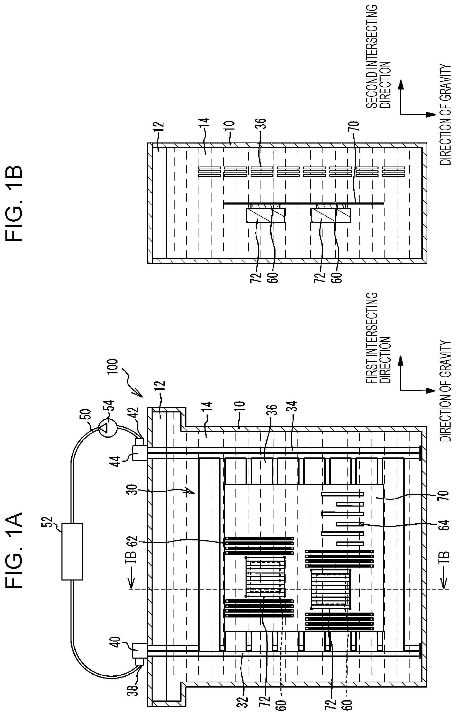
[0007] FIG. 1A is a see-through front view of an immersion tank according to a first embodiment, and FIG. 1B is a cross-sectional view taken along a line IB-IB of FIG. 1A;
[0008] FIG. 2A is a front view of a heat exchanger, and FIG. 2B is a bottom view;
[0009] FIG. 3A is a perspective view of the heat exchanger, and FIG. 3B is a cross-sectional view taken along a line IIIB-IIIB of FIG. 2A;
[0010] FIG. 4 is a see-through front view of an immersion tank according to a comparative example;
[0011] FIG. 5 is a cross-sectional view for explaining the effect of the immersion tank according to the first embodiment; and
[0012] FIG. 6A is a see-through front view of an immersion tank according to a second embodiment, and FIG. 6B is a cross-sectional view taken along a line VIB-VIB of FIG. 6A.
DESCRIPTION OF EMBODIMENTS
[0013] The method described in Japanese Laid-open Patent Publication No. 3-50897 leaves room for improvement from the aspect of improving the cooling performance by generating convection in the liquid coolant stored in the main tank body.
[0014] Hereinafter, embodiments will be described with reference to the drawings.
First Embodiment
[0015] FIG. 1A is a see-through front view of an immersion tank according to a first embodiment, and FIG. 1B is a cross-sectional view taken along a line IB-IB of FIG. 1A. As illustrated in FIG. 1A and FIG. 1B, an immersion tank 100 of the first embodiment includes a main tank body 10 and a heat exchanger 30 for liquid immersion cooling. The main tank body 10 has a space 12 inside. In the space 12, a coolant 14 is stored. The coolant 14 is a coolant having an electrical insulating property and thermal conductivity. The coolant 14 is a fluorine-based insulating coolant such as a fluorocarbon-based coolant, for example. The main tank body 10 is formed of plastic or stainless steel, for example.
[0016] In the main tank body 10, a wiring board 70 on which electronic components 60, 62, and 64 are mounted is accommodated while being immersed in the coolant 14. Since the coolant 14 has electrical insulating properties, the wiring board 70 on which the electronic components 60, 62, and 64 are mounted may be cooled by immersing in the coolant 14. The electronic component 60 is, for example, a central processing unit (CPU). The electronic components 62 and 64 are, for example, memories. The wiring board 70 is, for example, a printed wiring board. A heat sink 72 having a plurality of radiation fins may be provided on the main surface of the electronic component 60. As a result, the heat radiation area of the electronic component 60 is increased, so the electronic component 60 is effectively cooled. The heat sink 72 is formed of a material having a high thermal conductivity such as metal or the like, and is formed of, for example, aluminum.
[0017] The heat exchanger 30 is accommodated in the main tank body 10 and immersed in the coolant 14. The heat exchanger 30 is provided for cooling the coolant 14 stored in the main tank body 10. The heat exchanger 30 has an introduction pipe 32, a discharge pipe 34, and a plurality of connecting pipes 36 connecting between the introduction pipe 32 and the discharge pipe 34. The introduction pipe 32, the discharge pipe 34, and the connecting pipes 36 are formed of a material having high thermal conductivity such as metal or the like. As an example, the introduction pipe 32, the discharge pipe 34, and the connecting pipes 36 are formed of aluminum. The introduction pipe 32, the discharge pipe 34, and the connecting pipes 36 are not limited to a case where they are formed of the same material, and may be formed of different materials.
[0018] One each of the introduction pipe 32 and the discharge pipe 34 may be provided, however in the first embodiment, a case where a plurality of pipes is provided will be described as an example. The plurality of introduction pipes 32 is connected to a common introduction part 40 having one introduction port 38. The plurality of discharge pipes 34 is connected to a common discharge part 44 having one discharge port 42. The introduction port 38 and the discharge port 42 are connected to an external heat exchanger 52 such as a chiller or the like via a pipe 50 (e.g., a "transfer pipe"). A pump 54 is installed in the pipe 50.
[0019] A coolant (hereinafter referred to as circulating coolant) is sealed in the heat exchanger 30. When the pump 54 is driven, circulating coolant circulates between the heat exchanger 30 and the external heat exchanger 52. The heat exchanger 30 is immersed in the coolant 14 stored in the main tank body 10, so the circulating coolant flows in the heat exchanger 30, heat exchange occurs with the coolant 14, and the coolant 14 is cooled.
[0020] The introduction pipes 32 and the discharge pipes 34 extend perpendicular to the bottom surface of the main tank body 10, for example. The plurality of connecting pipes 36 extends in parallel to the bottom surface of the main tank body 10, for example. The term "extending perpendicular" is not limited to the case where the pipes extend completely perpendicularly to the bottom surface of the main tank body 10, and even a case where the pipes extend with a slight inclination with respect to the bottom surface of the main tank body 10 is included. Similarly, "extending in parallel" is not limited to the case where the pipes extend completely in parallel to the bottom surface of the main tank body 10, and even a case where the pipes extend with a slight inclination with respect to the bottom surface of the main tank body 10 is also included. In the first embodiment, the introduction pipes 32 and the discharge pipes 34 extend in the direction of gravity, and the plurality of connecting pipes 36 extends in the first intersecting direction intersecting (for example orthogonal to) the direction of gravity.
[0021] Here, the heat exchanger 30 will be described by using FIG. 2A to FIG. 3B together. FIG. 2A is a front view of the heat exchanger, and FIG. 2B is a bottom view. FIG. 3A is a perspective view of the heat exchanger, and FIG. 3B is a cross-sectional view taken along a line IIIB-IIIB of FIG. 2A. In FIG. 2B, the introduction pipes 32 and the discharge pipes 34 are illustrated while seeing through a part of the member. In FIG. 3A, the flow of the circulating coolant flowing through the heat exchanger 30 is indicated by arrows. The circulating coolant may be of the same type as the coolant 14 stored in the main tank body 10 or may be of a different type.
[0022] The plurality of introduction pipes 32 is in close proximity to each other and extend in parallel to each other in the gravity direction. The plurality of discharge pipes 34 is in close proximity to each other and extend in parallel to each other in the gravity direction. The plurality of connecting pipes 36 is connected between the introduction pipes 32 and the discharge pipes 34 and extend in the first intersecting direction intersecting the direction of gravity. For example, the plurality of connecting pipes 36 is such that the cross-sectional shape when cut in the direction of gravity is a flat shape whose longitudinal direction is the direction of gravity, however, may also be another shape such as a circular shape or the like The plurality of connecting pipes 36 is arranged in a plurality of rows in the second intersecting direction, with the second intersecting direction intersecting (for example orthogonal to) the direction of gravity and the first intersecting direction being the lateral direction of the flat shape. In addition, the plurality of connecting pipes 36 is arranged side by side in a plurality of stages also in the direction of gravity. Providing the plurality of connecting pipes 36 side by side in a plurality of stages in the direction of gravity is not limited to a case where the pipes are provided side by side in a plurality of stages completely in parallel to the direction of gravity, and a case of providing the pipes side by side in a plurality of stages that are slightly inclined with respect to the direction of gravity is also included. The width W in the lateral direction of the connecting pipes 36 is, for example, about 4 mm, and the length L in the longitudinal direction is, for example, about 45 mm. An interval D1 between the connecting pipes 36 arranged side by side in a plurality of rows is, for example, about 6 mm, and an interval D2 between the connecting pipes 36 arranged side by side in a plurality of stages is, for example, about 10 mm.
[0023] The connecting pipes 36 arranged side by side in a plurality of rows in the second intersecting direction are respectively connected between different introduction pipes 32 among the plurality of introduction pipes 32 and different discharge pipes 34 among the plurality of discharge pipes 34. For example, one of the plurality of rows in which the connecting pipes 36 are arranged is connected between one of the plurality of introduction pipes 32 and one of the plurality of discharge pipes 34. Another one of the plurality of rows of connecting pipes 36 is connected between another one of the plurality of introduction pipes 32 and another one of the plurality of discharge pipes 34.
[0024] The inside of a connecting pipe 36 is partitioned into a plurality of spaces 46, and a plurality of flow paths is formed. The circulating coolant flows inside the plurality of spaces 46 from the introduction pipe 32 side toward the discharge pipe 34 side. Here, the flow of the circulating coolant flowing through the heat exchanger 30 will be described with reference to FIG. 3A. The circulating coolant cooled by the external heat exchanger 52 (refer to FIG. 1A) is introduced into the introduction pipes 32 from the introduction port 38. The circulating coolant introduced into the introduction pipes 32 flows inside the introduction pipes 32 from the upper side to the lower side in the direction of gravity, and sequentially flows into the plurality of connecting pipes 36 in the process. The circulating coolant that has flowed into the connecting pipes 36 flows inside the spaces 46 formed in the connecting pipes 36 from the introduction pipe 32 side toward the discharge pipe 34 side and then flows into the discharge pipes 34. The circulating coolant that has flowed into the discharge pipes 34, flows inside the discharge pipes 34 from the lower side to the upper side in the direction of gravity, and then is discharged from the discharge port 42 toward the external heat exchanger 52.
[0025] In this way, the circulating coolant flows through the heat exchanger 30 and is not mixed with the coolant 14 stored in the main tank body 10. For example, it is conceivable that the coolant 14 stored in the main tank body 10 is circulated by a pump to an external heat exchanger provided outside the main tank body 10 to cool the coolant 14. In this case, when the wiring board 70 is put in and taken out from the main tank body 10, foreign matter may become mixed in the coolant 14, and the pump circulating the coolant 14 may fail. On the other hand, in the first embodiment, since the circulating coolant flowing through the heat exchanger 30 and the coolant 14 stored in the main tank body 10 are not mixed, even in a case where foreign matter is mixed in the coolant 14, failure of the pump 54 for circulating the circulating coolant may be suppressed.
[0026] Here, in explaining the effect of the immersion tank 100 of the first embodiment, an immersion tank of a comparative example will be described. FIG. 4 is a see-through front view of an immersion tank according to the comparative example. As illustrated in FIG. 4, in the immersion tank 500 of the comparative example, the heat exchanger 80 is immersed in the coolant 14 and accommodated in the main tank body 10. The heat exchanger 80 has an introduction pipe 82, a discharge pipe 84, and a flat plate member 86 in which a flow path is formed. A heat sink 88 having radiating fins may be provided on the main surface of the flat plate member 86. The flat plate member 86 is provided at a bottom portion positioned on the lower side in the direction of gravity of the main tank body 10. The wiring board 70 on which the electronic components 60, 62, and 64 are mounted is arranged on the upper side in the direction of gravity of the flat plate member 86. The introduction pipe 82 and the discharge pipe 84 are connected to an external heat exchanger 52 such as a chiller or the like via the pipe 50.
[0027] When the pump 54 is driven, the circulating coolant that is cooled by the external heat exchanger 52 is introduced into the introduction pipe 82. The circulating coolant introduced into the introduction pipe 82 flows through a flow path formed inside the flat plate member 86 and then is discharged from the discharge pipe 84 toward the external heat exchanger 52.
[0028] According to the comparative example, in order to cool the coolant 14 stored in the main tank body 10, the heat exchanger 80 is immersed in the coolant 14. The flat plate member 86 of the heat exchanger 80 is installed at a bottom portion of the main tank body 10, so the coolant 14 in the vicinity of the bottom portion of the main tank body 10 is cooled. However, the coolant 14 that is warmed by the electronic components 60, 62, and 64 tends to rise upward in the direction of gravity more than the electronic components 60, 62, and 64, while on the other hand, the coolant 14 that is cooled by the flat plate member 86 of the heat exchanger 80 tends to accumulate in the vicinity of the bottom portion positioned on the lower side in the direction of gravity of the main tank body 10. Therefore, the temperature difference between the circulating coolant flowing through the flat plate member 86 and the coolant 14 existing around the flat plate member 86 is small, and effective heat exchange is difficult to perform. In addition, it is difficult for convection to occur in the coolant 14. As a result, it is difficult to perform effective cooling of the electronic components 60, 62, and 64.
[0029] FIG. 5 is a cross-sectional view for explaining the effect of the immersion tank according to the first embodiment. As described using FIG. 1A and FIG. 1B, in the first embodiment, the heat exchanger 30 immersed in the coolant 14 has introduction pipes 32 and discharge pipes 34 extending in the direction of gravity and a plurality of connecting pipes 36 connected between the introduction pipes 32 and the discharge pipes 34. The plurality of connecting pipes 36 is arranged side by side in a plurality of rows in a second intersecting direction that intersects the direction of gravity and are arranged side by side in a plurality of stages in the direction of gravity. In this case, as illustrated in FIG. 5, the density of the coolant 14 that is warmed by the electronic component 60 is lower than that of the surrounding coolant 14, and as indicated by an arrow 90, rises toward the upward side in the direction of gravity. On the other hand, the coolant 14 that is cooled by the circulating coolant flowing in the connecting pipes 36 has a density higher than that of the surrounding coolant 14, and as indicated by an arrow 92, descends toward the lower side in the direction of gravity. At this time, the coolant 14 located between the connecting pipes 36 arranged side by side in a plurality of rows tends to be cooled by the circulating coolant flowing inside the connecting pipes 36, and because it is difficult for that coolant 14 to be affected by the coolant 14 existing outside the connecting pipes 36 arranged side by side in a plurality of rows, it is not easily warmed up. Therefore, a flow of coolant 14 descending toward the lower side in the direction of gravity as indicated by the arrow 92 tends to occur between the connecting pipes 36 arranged side by side in a plurality of rows.
[0030] Even when the connecting pipes 36 are arranged side by side in a plurality of stages in the direction of gravity, a flow of the coolant 14 descending toward the lower side in the direction of gravity as indicated by the arrow 92 tends to occur between the connecting pipes 36 arranged side by side in a plurality of rows. This is due to the following reason. For example, in a case where one large connecting pipe 36 extends in the direction of gravity from the upper end side to the lower end side of the introduction pipes 32 and the discharge pipes 34, the flow path resistance between the connecting pipes 36 arranged side by side in a plurality of rows becomes large. In this case, it becomes difficult for the coolant 14 to flow toward the lower side in the direction of gravity between the connecting pipes 36 arranged side by side in a plurality of rows. On the other hand, by providing connecting pipes 36 arranged side by side in a plurality of stages in the direction of gravity, the flow path resistance between the connecting pipes 36 arranged side by side in a plurality of rows becomes small. For this reason, a flow of the coolant 14 descending toward the lower side in the direction of gravity such as indicated by the arrow 92 tends to occur between the connecting pipes 36 arranged side by side in a plurality of rows.
[0031] By generating an upward flow and a downward flow in the coolant 14 stored in the main tank body 10 in this way, a flow in which the coolant 14 circulates inside the main tank body 10 is produced as indicated by arrows 90 to 96. As a result, the temperature difference of the coolant 14 stored in the main tank body 10 becomes small. Therefore, heat exchange between the circulating coolant flowing through the heat exchanger 30 and the coolant 14 stored in the main tank body 10 is effectively performed, and the electronic component 60 is effectively cooled.
[0032] According to the first embodiment, as illustrated in FIG. 1A, the heat exchanger 30 immersed in the coolant 14 includes introduction pipes 32 into which the circulating coolant is introduced, discharge pipes 34 for discharging the circulating coolant, and a plurality of connecting pipes 36 that connects between the introduction pipes 32 and the discharge pipes 34 and through which the circulating coolant flows from the introduction pipes 32 toward the discharge pipes 34. As illustrated in FIG. 3A and FIG. 3B, the plurality of connecting pipes 36 is arranged side by side in a plurality of rows in a second intersecting direction intersecting the direction of gravity and arranged side by side in a plurality of stages in the direction of gravity. By arranging the connecting pipes 36 side by side in a plurality of rows in the second intersecting direction intersecting the direction of gravity and side by side in a plurality of stages in the direction of gravity in this way, as described with reference to FIG. 5, a downward flow may be effectively generated in the coolant 14 stored in the main tank body 10. Therefore, convection may be effectively generated in the coolant 14 stored in the main tank body 10, coupled with an upward flow by the coolant 14 that is warmed by the electronic component 60 or the like, so the cooling performance may be improved.
[0033] As the number of rows of connecting pipes 36 arranged side by side in a plurality of rows in the second intersecting direction intersecting the direction of gravity increases, it becomes difficult for the coolant 14 existing between the connecting pipes 36 located inside the rows to be influenced by the coolant 14 existing further outside than the connecting pipes 36 arranged side by side in the plurality of rows. For example, as the number of rows of the connecting pipes 36 arranged side by side in a plurality of rows increases, it becomes easy for the coolant 14 existing between the connecting pipes 36 located inside the rows to be cooled. Therefore, a large downward flow tends to occur, and a large convection tends to occur in the coolant 14. For this reason, the number of rows of the connecting pipes 36 arranged side by side in a plurality of rows in the second intersecting direction is preferably three rows or more, and more preferably five rows or more, and even more preferably eight rows or more. From the aspect of suppressing the enlargement of the main tank body 10, the number of rows of the connecting pipes 36 arranged side by side in a plurality of rows in the second intersecting direction is preferably ten rows or less, and more preferably seven rows or less, and even more preferably four rows or less.
[0034] As illustrated in FIG. 3A and FIG. 3B, the plurality of connecting pipes 36 has a cross-sectional shape having a longitudinal direction and a lateral direction. The direction of gravity is taken to be the longitudinal direction and the second intersecting direction intersecting the direction of gravity is taken to be the lateral direction, and preferably the plurality of connecting pipes 36 is arranged side by side in a plurality of rows in the second intersecting direction and arranged side by side in a plurality of stages in the direction of gravity. As a result, the area where the connecting pipes 36 and the coolant 14 contact, among the connecting pipes 36 arranged side by side in a plurality of rows may be increased as compared with a case where the cross-sectional shape of the connecting pipes 36 is a circular shape, for example. Therefore, the coolant 14 may be effectively cooled by the circulating coolant flowing in the connecting pipes 36, and a downward flow may be effectively generated. Even in a case where the connecting pipes 36 are arranged side by side in a plurality of rows, the installation space may be reduced. Note that even when the cross-sectional shape of the connecting pipes 36 is a circular shape, the effect of improving the cooling performance by generating convection in the coolant 14 is obtained.
[0035] As illustrated in FIG. 3B, the interior of the connecting pipes 36 is preferably partitioned into a plurality of spaces 46. As a result, the circulating coolant flowing in the connecting pipes 36 may be suppressed from being biased toward a part inside the connecting pipes 36, and wall portions partitioning the interior of the connecting pipes 36 into a plurality of spaces 46 also contribute to cooling of the coolant 14 by the circulating coolant. Therefore, the cooling effect of the coolant 14 stored in the main tank body 10 may be improved. By partitioning the interior of the connecting pipes 36 into a plurality of spaces 46, the strength of the connecting pipes 36 may be improved as compared with a case where the connecting pipes 36 are not partitioned into a plurality of spaces but is a single space.
[0036] As illustrated in FIG. 1A and FIG. 1B, the case of arranging the plurality of connecting pipes 36 so as to be shifted in a direction intersecting the direction of gravity with respect to the wiring board 70 on which the electronic component 60 and the like are mounted is preferable. As a result, a circulating flow of the coolant 14 stored in the main tank body 10 may be effectively generated as described with reference to FIG. 5. In FIG. 1A and FIG. 1B, the wiring board 70 is arranged near the center of the connecting pipes 36 arranged side by side in a plurality of stages in the direction of gravity, but may also be biased toward the upper side or the lower side. In FIG. 1A and FIG. 1B, the plurality of connecting pipes 36 is arranged so as to be shifted in the second intersecting direction with respect to the wiring board 70, however, even in a case of being arranged so as to be shifted in the first intersecting direction, a flow in which the coolant 14 stored in the main tank body 10 circulates may be effectively generated. As illustrated in FIG. 1A and FIG. 1B, from the aspect of effectively creating a circulating flow of the coolant 14 stored in the main tank body 10, preferably the wiring board 70 is accommodated in the main tank body 10 so as to stand upright in the direction of gravity.
[0037] The coolant 14 stored in the main tank body 10 and the circulating coolant flowing through the heat exchanger 30 may be the same type of coolant or may be different kinds of coolant. Even in a case where the circulating coolant flowing through the heat exchanger 30 flows out to the main tank body 10 for some reason, by making the coolant 14 stored in the main tank body 10 and the circulating coolant flowing through the heat exchanger 30 be the same type of coolant, the adverse effects on the electronic component 60 and the like may be suppressed. In addition, by making the coolant 14 stored in the main tank body 10 and the circulating coolant flowing through the heat exchanger 30 be different types of coolant, a coolant having a high heat dissipating capacity suitable for cooling may be adopted as the circulating coolant. For example, the coolant 14 stored in the main tank body 10 may be a fluorine-based insulating coolant and the circulating coolant flowing through the heat exchanger 30 may be water or a propylene glycol-based coolant.
[0038] In the first embodiment, a case in which the introduction pipes 32 and the discharge pipes 34 extend in the direction of gravity was described as an example, however the technique is not limited to this case and these pipes may extend in a direction inclined from the direction of gravity.
Second Embodiment
[0039] FIG. 6A is a see-through front view of an immersion tank according to a second embodiment, and FIG. 6B is a cross-sectional view taken along a line VIB-VIB of FIG. 6A. In the case of the immersion tank 100 of the first embodiment, as illustrated in FIG. 1A and FIG. 1B, an example is described in which the wiring board 70 on which the electronic component 60 and the like are mounted is arranged on only one side with respect to the heat exchanger 30. However, as in the case of the immersion tank 200 of the second embodiment, the wiring board 70 on which the electronic component 60 and the like are mounted may be arranged on one side of the heat exchanger 30, and a wiring board 74 on which an electronic component 66 and the like are mounted may be arranged on the other side. In this case, the upward flow of the coolant 14 that is warmed by the electronic components 60 and 66 is increased, so convection of the coolant 14 stored in the main tank body 10 may be effectively generated.
[0040] Although embodiments have been described in detail above, the embodiments are not limited to the specific embodiments, and various modifications and changes may be made within the range of the gist of the embodiments described in the claims.
[0041] All examples and conditional language provided herein are intended for the pedagogical purposes of aiding the reader in understanding the invention and the concepts contributed by the inventor to further the art, and are not to be construed as limitations to such specifically recited examples and conditions, nor does the organization of such examples in the specification relate to a showing of the superiority and inferiority of the invention. Although one or more embodiments of the present invention have been described in detail, it should be understood that the various changes, substitutions, and alterations could be made hereto without departing from the spirit and scope of the invention.
* * * * *
D00000
D00001
D00002
D00003
D00004
D00005
D00006
XML
uspto.report is an independent third-party trademark research tool that is not affiliated, endorsed, or sponsored by the United States Patent and Trademark Office (USPTO) or any other governmental organization. The information provided by uspto.report is based on publicly available data at the time of writing and is intended for informational purposes only.
While we strive to provide accurate and up-to-date information, we do not guarantee the accuracy, completeness, reliability, or suitability of the information displayed on this site. The use of this site is at your own risk. Any reliance you place on such information is therefore strictly at your own risk.
All official trademark data, including owner information, should be verified by visiting the official USPTO website at www.uspto.gov. This site is not intended to replace professional legal advice and should not be used as a substitute for consulting with a legal professional who is knowledgeable about trademark law.