Radiator Fan
Eisen; Dennis ; et al.
U.S. patent application number 15/955419 was filed with the patent office on 2019-10-17 for radiator fan. The applicant listed for this patent is JARO THERMAL, INC.. Invention is credited to Yen-Yu Chen, Dennis Eisen, Wen-Dong Huang, Shih-Chieh Su, Ming-Yin Wang.
| Application Number | 20190316598 15/955419 |
| Document ID | / |
| Family ID | 68160785 |
| Filed Date | 2019-10-17 |

| United States Patent Application | 20190316598 |
| Kind Code | A1 |
| Eisen; Dennis ; et al. | October 17, 2019 |
Radiator Fan
Abstract
A radiator fan has a case, a stator assembly, and an impeller assembly. The stator assembly is assembled in the case. The impeller assembly is assembled in the case and has an impeller, a shaft, and a magnetic ring. The impeller has a hub and multiple blades. The hub has a hub diameter. The multiple blades are connected to the hub, are disposed around the hub at equal angular intervals, and have a blade span diameter. A ratio of the hub diameter to the blade span diameter is greater than or equal to 0.395 and is less than or equal to 0.515. The shaft is rotatably assembled to the case. The magnetic ring is fixed inside the hub, is disposed around the shaft, and is separated from the shaft by a gap.
| Inventors: | Eisen; Dennis; (Kaohsiung City, TW) ; Wang; Ming-Yin; (Kaohsiung City, TW) ; Su; Shih-Chieh; (Kaohsiung City, TW) ; Chen; Yen-Yu; (Kaohsiung City, TW) ; Huang; Wen-Dong; (Kaohsiung City, TW) | ||||||||||
| Applicant: |
|
||||||||||
|---|---|---|---|---|---|---|---|---|---|---|---|
| Family ID: | 68160785 | ||||||||||
| Appl. No.: | 15/955419 | ||||||||||
| Filed: | April 17, 2018 |
| Current U.S. Class: | 1/1 |
| Current CPC Class: | F04D 29/329 20130101; F04D 29/545 20130101; F04D 29/384 20130101; F04D 25/0613 20130101; F04D 29/667 20130101; F04D 25/08 20130101 |
| International Class: | F04D 29/38 20060101 F04D029/38; F04D 29/32 20060101 F04D029/32; F04D 29/54 20060101 F04D029/54; F04D 25/06 20060101 F04D025/06; F04D 29/66 20060101 F04D029/66; F04D 25/08 20060101 F04D025/08 |
Claims
1. A radiator fan comprising: a case; a stator assembly assembled in the case; and an impeller assembly assembled in the case and having an impeller having a hub having a hub diameter; multiple blades connected to the hub, disposed around the hub at equal angular intervals, and having a blade span diameter; and a ratio of the hub diameter to the blade span diameter being greater than or equal to 0.395 and being less than or equal to 0.515; a shaft rotatably assembled to the case; and a magnetic ring fixed inside the hub, disposed around the shaft, and separated from the shaft by a gap.
2. The radiator fan as claimed in claim 1, wherein the hub has a basal portion shaped as a tube with two opposite ends; and a cap portion formed at one of the two opposite ends of the basal portion and shaped as a hemisphere.
3. The radiator fan as claimed in claim 1, wherein the hub has a basal portion shaped as a tube with two opposite ends; and a cap portion formed at one of the two opposite ends of the basal portion and shaped as a cone.
4. The radiator fan as claimed in claim 1, wherein the hub has a basal portion shaped as a tube with two opposite ends; and a cap portion formed at one of the two opposite ends of the basal portion and shaped as a cone with a flat top.
5. The radiator fan as claimed in claim 1, wherein the ratio of the hub diameter to the blade span diameter is greater than or equal to 0.430 and is less than or equal to 0.480.
6. The radiator fan as claimed in claim 2, wherein the ratio of the hub diameter to the blade span diameter is greater than or equal to 0.430 and is less than or equal to 0.480.
7. The radiator fan as claimed in claim 3, wherein the ratio of the hub diameter to the blade span diameter is greater than or equal to 0.430 and is less than or equal to 0.480.
8. The radiator fan as claimed in claim 4, wherein the ratio of the hub diameter to the blade span diameter is greater than or equal to 0.430 and is less than or equal to 0.480.
9. The radiator fan as claimed in claim 1, wherein the radiator fan has a reference plane; the shaft has an axis being perpendicular to the reference plane of the radiator fan; each one of the multiple blades has an inside edge connected to a periphery of the hub and having a top end; and an outside edge being distal from the inside edge and having a top end; and a distance defined between the reference plane of the radiator fan and the top end of the inside edge is smaller than a distance defined between the top end of the outside edge and the reference plane of the radiator fan.
10. The radiator fan as claimed in claim 2, wherein the radiator fan has a reference plane; the shaft has an axis being perpendicular to the reference plane of the radiator fan; each one of the multiple blades has an inside edge connected to a periphery of the hub and having a top end; and an outside edge being distal from the inside edge and having a top end; and a distance defined between the reference plane of the radiator fan and the top end of the inside edge is smaller than a distance defined between the top end of the outside edge and the reference plane of the radiator fan.
11. The radiator fan as claimed in claim 3, wherein the radiator fan has a reference plane; the shaft has an axis being perpendicular to the reference plane of the radiator fan; each one of the multiple blades has an inside edge connected to a periphery of the hub and having a top end; and an outside edge being distal from the inside edge and having a top end; and a distance defined between the reference plane of the radiator fan and the top end of the inside edge is smaller than a distance defined between the top end of the outside edge and the reference plane of the radiator fan.
12. The radiator fan as claimed in claim 4, wherein the radiator fan has a reference plane; the shaft has an axis being perpendicular to the reference plane of the radiator fan; each one of the multiple blades has an inside edge connected to a periphery of the hub and having a top end; and an outside edge being distal from the inside edge and having a top end; and a distance defined between the reference plane of the radiator fan and the top end of the inside edge is smaller than a distance defined between the top end of the outside edge and the reference plane of the radiator fan.
13. The radiator fan as claimed in claim 9, wherein the case has a shroud having a space disposed inside the shroud; a first vent communicating with the space of the shroud; and a second vent communicating with the shroud; a base board disposed below the space of the shroud; and an axial tube portion disposed in the space and connected to the base board; the first vent and the second vent are disposed at two different sides of the shroud; the stator assembly is assembled to the base board and has multiple wire coils disposed around the axial tube portion; the impeller assembly is assembled in the space of the shroud; the shaft of the impeller assembly is rotatably assembled in the axial tube portion; the hub of the impeller has a chamber with an opening facing downward; and the magnetic ring is fastened to an inner surface of the chamber and disposed around the multiple wire coils.
14. The radiator fan as claimed in claim 10, wherein the case has a shroud having a space disposed inside the shroud; a first vent communicating with the space of the shroud; and a second vent communicating with the shroud; a base board disposed below the space of the shroud; and an axial tube portion disposed in the space and connected to the base board; the first vent and the second vent are disposed at two different sides of the shroud; the stator assembly is assembled to the base board and has multiple wire coils disposed around the axial tube portion; the impeller assembly is assembled in the space of the shroud; the shaft of the impeller assembly is rotatably assembled in the axial tube portion; the hub of the impeller has a chamber with an opening facing downward; and the magnetic ring is fastened to an inner surface of the chamber and disposed around the multiple wire coils.
15. The radiator fan as claimed in claim 11, wherein the case has a shroud having a space disposed inside the shroud; a first vent communicating with the space of the shroud; and a second vent communicating with the shroud; a base board disposed below the space of the shroud; and an axial tube portion disposed in the space and connected to the base board; the first vent and the second vent are disposed at two different sides of the shroud; the stator assembly is assembled to the base board and has multiple wire coils disposed around the axial tube portion; the impeller assembly is assembled in the space of the shroud; the shaft of the impeller assembly is rotatably assembled in the axial tube portion; the hub of the impeller has a chamber with an opening facing downward; and the magnetic ring is fastened to an inner surface of the chamber and disposed around the multiple wire coils.
16. The radiator fan as claimed in claim 12, wherein the case has a shroud having a space disposed inside the shroud; a first vent communicating with the space of the shroud; and a second vent communicating with the shroud; a base board disposed below the space of the shroud; and an axial tube portion disposed in the space and connected to the base board; the first vent and the second vent are disposed at two different sides of the shroud; the stator assembly is assembled to the base board and has multiple wire coils disposed around the axial tube portion; the impeller assembly is assembled in the space of the shroud; the shaft of the impeller assembly is rotatably assembled in the axial tube portion; the hub of the impeller has a chamber with an opening facing downward; and the magnetic ring is fastened to an inner surface of the chamber and disposed around the multiple wire coils.
17. The radiator fan as claimed in claim 13, wherein the first vent and the second vent are respectively disposed at a top portion of the shroud and a bottom portion of the shroud.
18. The radiator fan as claimed in claim 16, wherein the first vent and the second vent are respectively disposed at a top portion of the shroud and a bottom portion of the shroud.
19. The radiator fan as claimed in claim 13, wherein the first vent is disposed at a top portion of the shroud; and the second vent is laterally defined through the shroud.
20. The radiator fan as claimed in claim 16, wherein the first vent is disposed at a top portion of the shroud; and the second vent is laterally defined through the shroud.
Description
BACKGROUND OF THE INVENTION
1. Field of the Invention
[0001] The present invention relates to a radiator fan, and more particularly to a radiator fan that produces very low noise and is capable of generating sufficient airflow.
2. Description of Related Art
[0002] A conventional radiator fan is a device that is widely used for cooling. In general, the conventional radiator fan has a case, a stator assembly, and an impeller assembly. The stator assembly has multiple wire coils. The impeller assembly has a hub and a magnetic ring fixed inside the hub. The magnetic ring is mounted around the multiple wire coils and separated from the multiple wire coils by a gap. The stator assembly controls the multiple wire coils to shift the magnetic field, to attract or repel the magnetic ring, and to drive the impeller assembly. The impeller generates airflow for cooling during spinning.
[0003] In the field of radiator fans, sufficient airflow, high static pressure, and low noise are the key features for promoting performance of the radiator fans. Taking the radiator fan applied to a car audio for instance, in order to avoid the noise of the radiator fan from diminishing performing quality of the car audio, low noise is a crucial key feature for promoting the performance of the radiator fan.
[0004] However, as the noise of the radiator fan is lower, the airflow generated by the radiator fan may be more insufficient. How to promote volume of airflow in premise of lowering the noise of the radiator fan is an important problem to be solved in the design and configurations of the radiator fans.
[0005] To promote the performance of the conventional radiator fan, the present invention provides a radiator fan to mitigate or obviate the aforementioned problems.
SUMMARY OF THE INVENTION
[0006] The main objective of the present invention is to provide a radiator fan that has low noise and generates sufficient airflow during operation.
[0007] The radiator fan comprises a case, a stator assembly, and an impeller assembly. The stator assembly is assembled in the case. The impeller assembly is assembled in the case and has an impeller, a shaft, and a magnetic ring. The impeller has a hub and multiple blades. The hub has a hub diameter. The multiple blades are connected to the hub, are disposed around the hub at equal angular intervals, and have a blade span diameter. A ratio of the hub diameter to the blade span diameter is greater than or equal to 0.395 and is less than or equal to 0.515. The shaft is rotatably assembled to the case. The magnetic ring is fixed inside the hub, is disposed around the shaft, and is separated from the shaft by a gap.
[0008] Other objects, advantages, and novel features of the invention will become more apparent from the following detailed description when taken in conjunction with the accompanying drawings.
BRIEF DESCRIPTION OF THE DRAWINGS
[0009] FIG. 1 is a perspective view of a first embodiment of a radiator fan in accordance with the present invention;
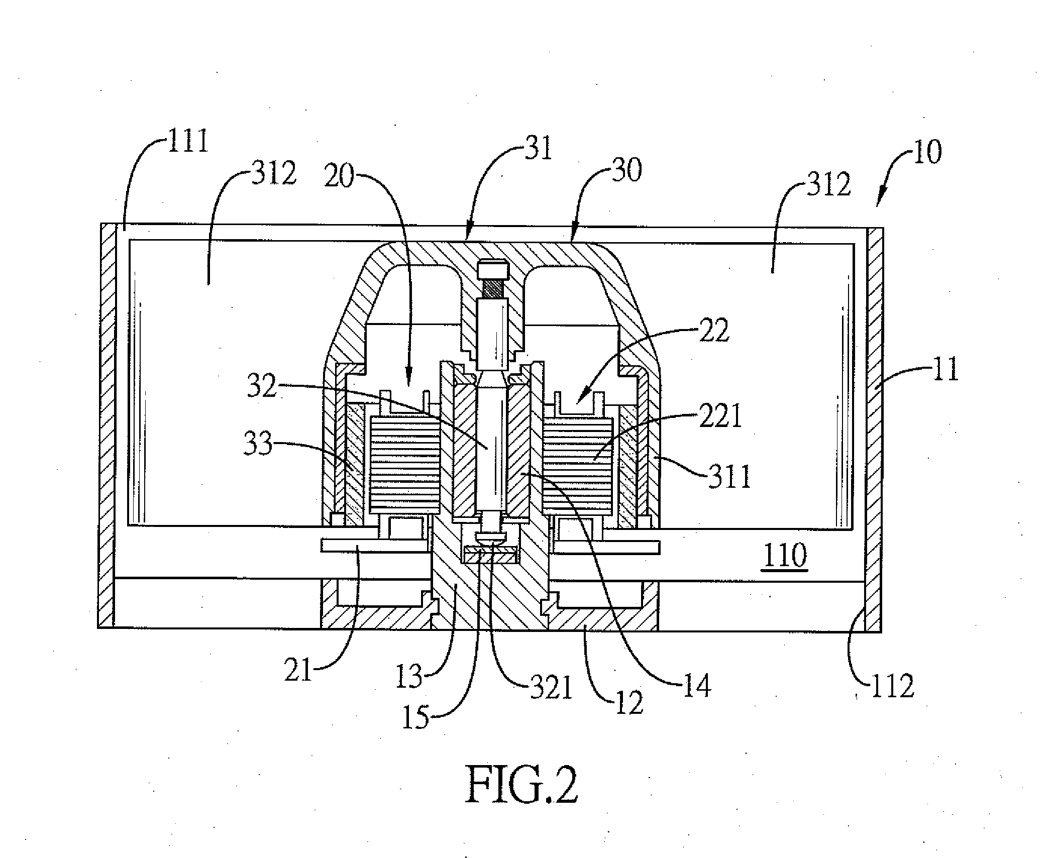
[0010] FIG. 2 is a side view in partial section of the radiator fan in FIG. 1;
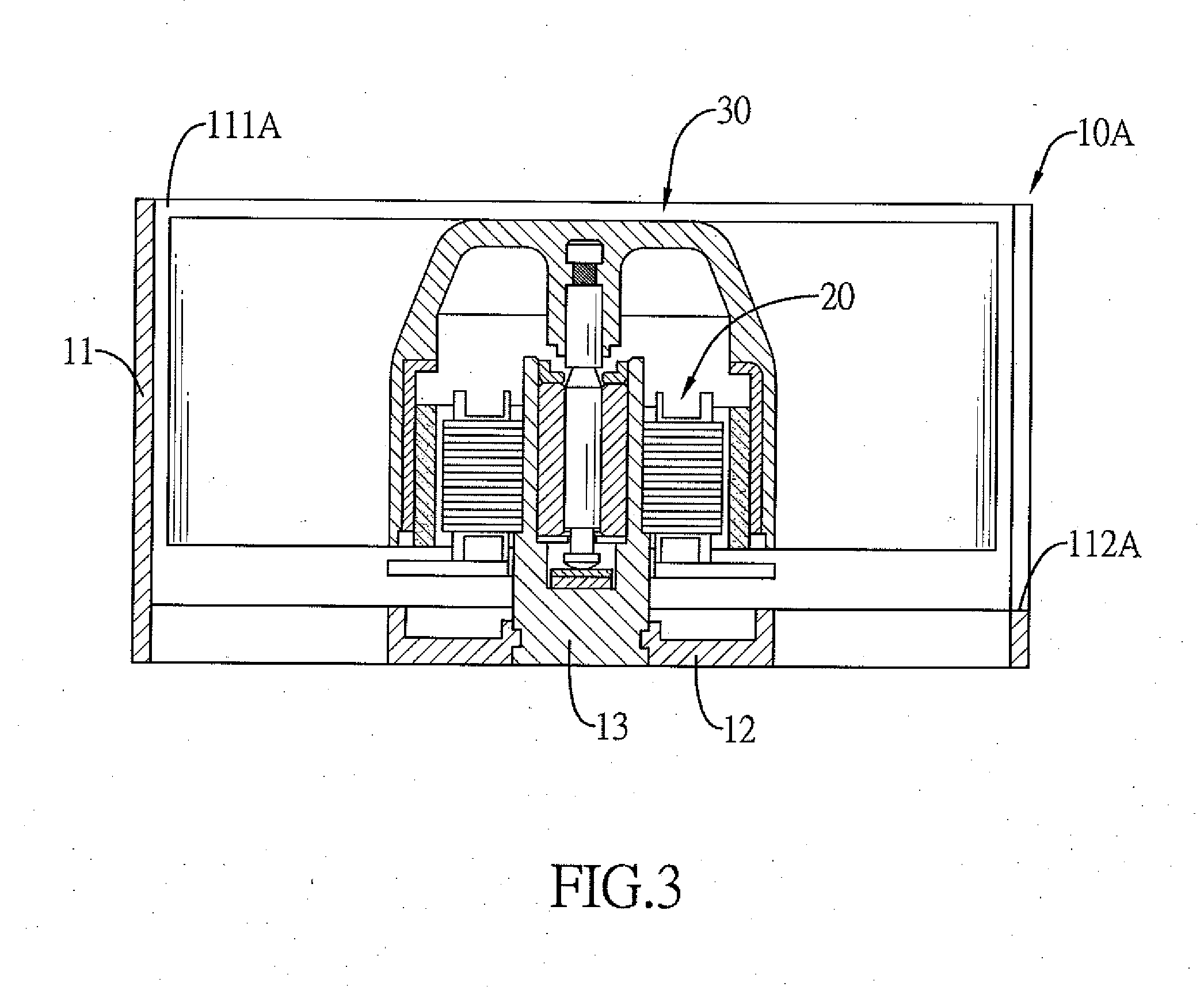
[0011] FIG. 3 is a side view in partial section of a second embodiment of a radiator fan in accordance with the present invention;
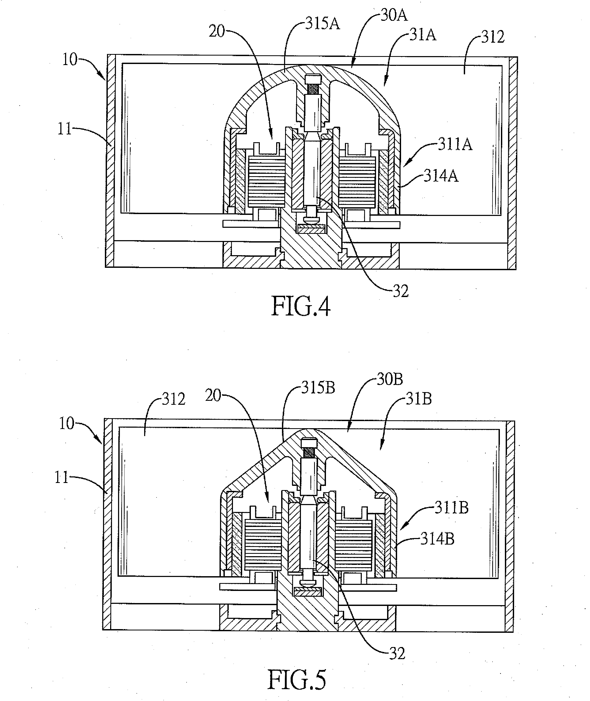
[0012] FIG. 4 is a side view in partial section of a third embodiment of a radiator fan in accordance with the present invention;
[0013] FIG. 5 is a side view in partial section of a fourth embodiment of a radiator fan in accordance with the present invention;
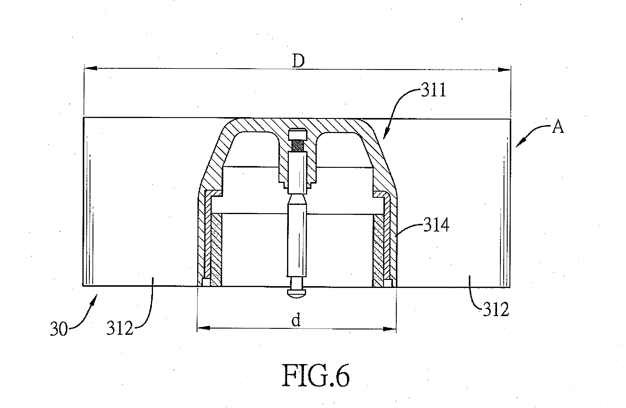
[0014] FIG. 6 is a side view in partial section of an impeller assembly in FIG. 3;
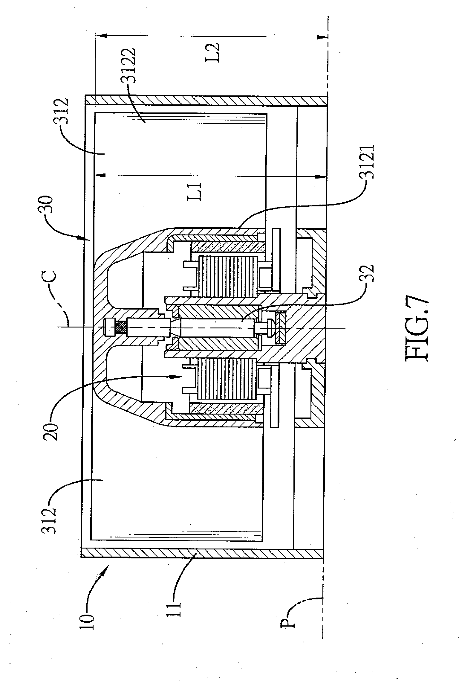
[0015] FIG. 7 is another side view in partial section of the radiator fan in FIG. 1; and
[0016] FIG. 8 is a side view in partial section of a fifth embodiment of a radiator fan in accordance with the present invention.
DETAILED DESCRIPTION OF PREFERRED EMBODIMENTS
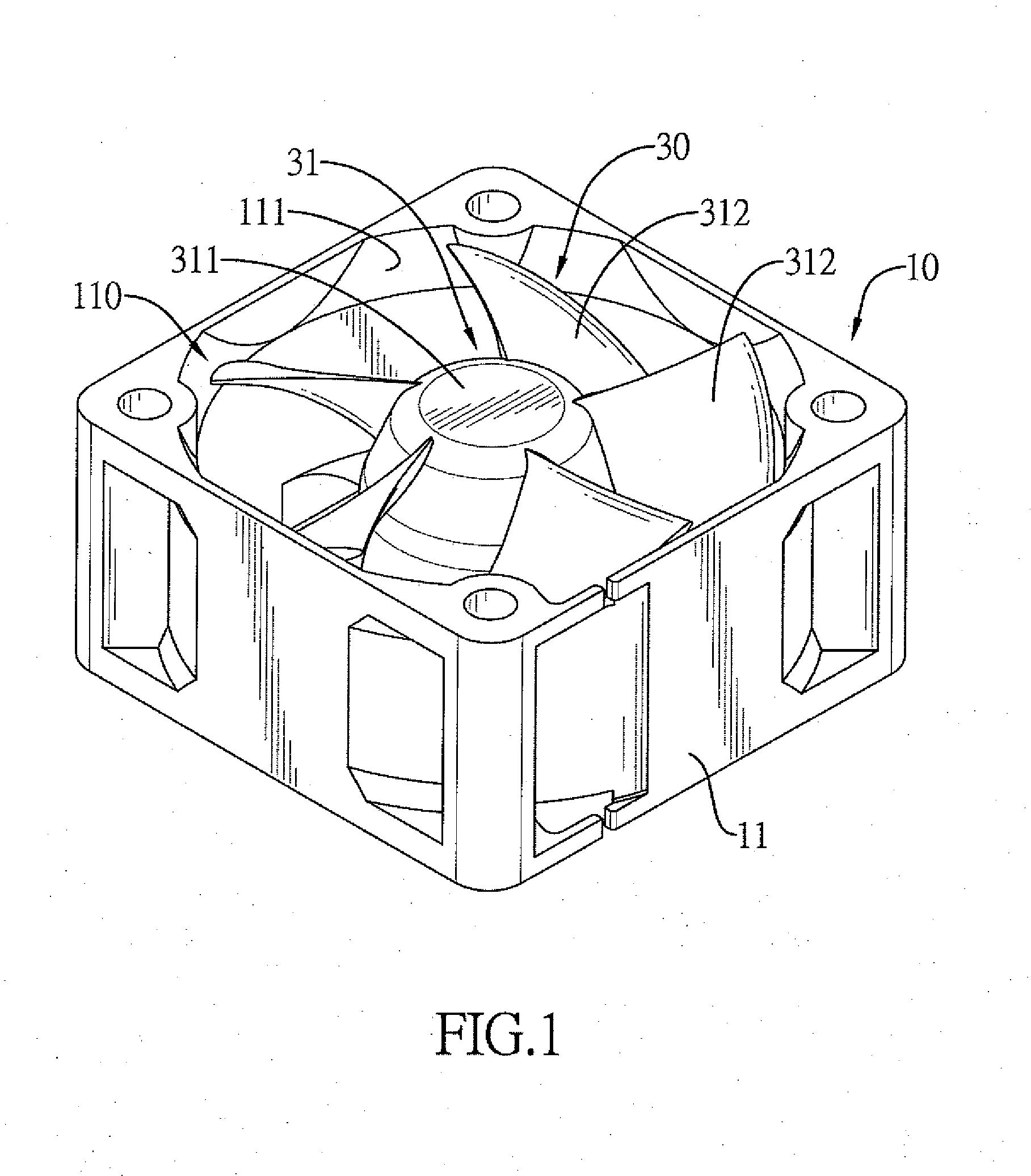
[0017] FIGS. 1 to 5 show multiple embodiments of a radiator fan in accordance with the present invention, and each embodiment of the radiator fan has a reference plane P, a case 10, 10A, a stator assembly 20, and an impeller assembly 30, 30A, 30B.
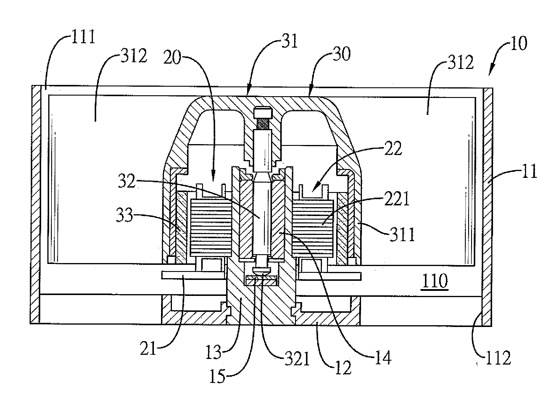
[0018] With reference to FIGS. 1 and 2, in the first embodiment of the present invention, the case 10 has a shroud 11, a base board 12, and an axial tube portion 13. The shroud 11 has a space 110, a first vent 111, and a second vent 112. The space 110 is disposed inside the shroud 11. The first vent 111 and the second vent 112 are respectively disposed at a top portion and a bottom portion of the shroud 11, and both communicate with the space 110. The base board 12 is disposed below the space 110. The axial tube portion 13 is disposed in the space 110 and is connected to the base board 12. With reference to FIG. 1, in the first embodiment of the present invention, the second vent 112 has multiple venting holes defined through the base board 12 and disposed around the axial tube portion 13.
[0019] With reference to FIG. 3, a second embodiment of a radiator fan in accordance with the present invention also has the case 10, the stator assembly 20, and the impeller assembly 30. In the second embodiment of the present invention, the first vent 111 is also disposed at the top portion of the shroud 11, but the second vent 112 is laterally defined through the shroud 11 of the case 10. The first vent 111 and the second vent 112 may each be an inlet or an outlet of airflow optionally.
[0020] With reference to FIGS. 2, 4, and 5, in the first, third, and fourth embodiments of the present invention, the stator assembly 20 is assembled in the case 10. The stator assembly 20 is assembled to the base board 12 of the case 10 and has a circuit board 21 and a stator 22 with multiple wire coils 221. The circuit board 21 is connected to a power supply by an electrical wire. The multiple wire coils 221 are disposed around the axial tube portion 13 of the case 10 and are electrically connected to the circuit board 21. The multiple wire coils 21 are controlled by the circuit board 21 to shift magnetic fields.
[0021] With reference to FIGS. 2, 4, and 5, the impeller assembly 30, 30A, 30B is assembled in the case 10. The impeller assembly 30, 30a, 30B has an impeller 31, 31A, 31B, a shaft 32, and a magnetic ring 33.
[0022] The impeller 31, 31A, 31B has an axial direction, a hub 311, 311A, 311B, and multiple blades 312. The axial direction of the impeller 31, 31A, 31B is perpendicular to the reference plane P of the radiator fan. The hub 311, 311A, 311B is disposed along the axial direction of the impeller 31, 31A, 31B, is hollow, has a hub diameter d, and a chamber with an opening facing downward. The multiple blades 312 are connected to the hub 311, 311A, 311B, are disposed around the hub 311, 311A, 311B, and have a blade span diameter D. A ratio d/D of the hub diameter d to the blade span diameter D is greater than or equal to 0.395 and is less than or equal to 0.515 (0.3958.ltoreq.d/D.ltoreq.0.515). Preferably, the ratio d/D of the hub diameter d to the blade span diameter D is greater than or equal to 0.430 and is less than or equal to 0.480 (0.430.ltoreq.d/D.ltoreq.0.480).
[0023] Each one of the multiple blades 312 has an inside edge 3121 connected to a periphery of the hub 311, 311A, 311B and an outside edge 3122 being distal from the inside edge 3121. The inside edge 3121 of each one of the multiple blades 312 has a top end. The outside edge 3122 of each one of the multiple blades 312 has a top end. With reference to FIG. 7, a distance L1 defined between the reference plane P of the radiator fan and the top end of the inside edge 3121 is smaller than a distance L2 defined between the top end of the outside edge 3122 and the reference plane P of the radiator fan. With reference to FIG. 8, the distance Li defined between the reference plane P of the radiator fan and the top end of the inside edge 3121 is smaller than the distance L2 defined between the top end of the outside edge 3122 and the reference plane P of the radiator fan.
[0024] The shaft 32 is assembled in the hub 311, 311A, 311B along the axial direction of the impeller 31, 31A, 31B and is rotatably assembled to the case 10. The magnetic ring 33 is made of a permanent magnet, is fixed inside the hub 311, 311A, 311B, is disposed around the shaft 32, and is separated from the shaft 32 by a gap. The magnetic ring 33 is fastened to an inner surface of the chamber of the hub 311, 311A, 311B. The gap between the shaft 32 and the magnetic ring 33 makes the stator assembly 20 magnetically drive the impeller assembly 30, 30A, 30B to spin.
[0025] With reference to FIGS. 2, 4, and 5, the impeller assembly 30, 30A, 30B is assembled in the space 110 of the shroud 11. The impeller 31, 31A, 31B is pivotally connected to the axial tube portion 13 of the case 10 by the shaft 32. A bearing 14 is mounted around the shaft 32 and is disposed between the shaft 32 and the axial tube portion 13 optionally. A wear-resisting pad 15 may be disposed inside the axial tube portion 13 and is disposed at a bottom end of the shaft 32. The bottom end of the shaft 32 may be curved to reduce a contact area between the bottom end of the shaft 32 and the wear-resisting pad 15, and lower down friction and noise during spinning of the impeller assembly 30, 30A, 30B.
[0026] With reference to FIGS. 1 and 2, the hub 311 has a basal portion and a cap portion. The basal portion is shaped as a tube with two opposite ends. The cap portion of the hub 311 is formed at one of the two opposite ends of the basal potion. With reference to FIGS. 1 to 3, the cap portion is shaped as a cone with a flat top. With reference to FIG. 4, the cap portion 315A is shaped as a hemisphere.
[0027] With reference to FIG. 5, the cap portion 315B is shaped as a cone. With reference to FIGS. 2 to 4, the circuit board 21 controls the multiple wire coils 221 to shift magnetic fields, to attract or repel the magnetic ring 33, and to drive the magnetic ring 33 to spin with the impeller 31, 31A, 31B.
[0028] By adjusting the ratio d/D of the hub diameter d to the blade span diameter D, the radiator fan in accordance with the present invention downsizes the hub 311, 311A, 311B and enlarges an area of each one of the multiple blades 312 in premise of lowing noise and generating sufficient airflow.
[0029] Even though numerous characteristics and advantages of the present invention have been set forth in the foregoing description, together with details of the structure and features of the invention, the disclosure is illustrative only. Changes may be made in the details, especially in matters of shape, size, and arrangement of parts within the principles of the invention to the full extent indicated by the broad general meaning of the terms in which the appended claims are expressed.
* * * * *
D00000
D00001
D00002
D00003
D00004
D00005
D00006
D00007
XML
uspto.report is an independent third-party trademark research tool that is not affiliated, endorsed, or sponsored by the United States Patent and Trademark Office (USPTO) or any other governmental organization. The information provided by uspto.report is based on publicly available data at the time of writing and is intended for informational purposes only.
While we strive to provide accurate and up-to-date information, we do not guarantee the accuracy, completeness, reliability, or suitability of the information displayed on this site. The use of this site is at your own risk. Any reliance you place on such information is therefore strictly at your own risk.
All official trademark data, including owner information, should be verified by visiting the official USPTO website at www.uspto.gov. This site is not intended to replace professional legal advice and should not be used as a substitute for consulting with a legal professional who is knowledgeable about trademark law.