Orthopedic Implant In The Form Of A Plate To Be Fixed Between Two Bone Parts
Prandi; Bernard ; et al.
U.S. patent application number 16/429834 was filed with the patent office on 2019-09-19 for orthopedic implant in the form of a plate to be fixed between two bone parts. The applicant listed for this patent is Stryker European Holdings I, LLC. Invention is credited to Bernard Prandi, Charles P. Wapner, Keith Wapner, Peter W. Wapner.
| Application Number | 20190282281 16/429834 |
| Document ID | / |
| Family ID | 40433892 |
| Filed Date | 2019-09-19 |
| United States Patent Application | 20190282281 |
| Kind Code | A1 |
| Prandi; Bernard ; et al. | September 19, 2019 |
Orthopedic Implant In The Form Of A Plate To Be Fixed Between Two Bone Parts
Abstract
The invention relates to a plate fixed between two bone parts by way of screws engaged in holes formed in the thickness of said plate. The plate comprises an angled member or rib which is inclined according to an angle of between about 30.degree. and 60.degree. in relation to the plane defined by the plate. The angled member or rib has a hole for engaging a screw and is located in the central part of the width, over a determined part of the length of the plate, so that the screw brings the two bone parts into a compressive position.
| Inventors: | Prandi; Bernard; (Rennes, FR) ; Wapner; Keith; (Philadelphia, PA) ; Wapner; Charles P.; (Media, PA) ; Wapner; Peter W.; (Media, PA) | ||||||||||
| Applicant: |
|
||||||||||
|---|---|---|---|---|---|---|---|---|---|---|---|
| Family ID: | 40433892 | ||||||||||
| Appl. No.: | 16/429834 | ||||||||||
| Filed: | June 3, 2019 |
Related U.S. Patent Documents
| Application Number | Filing Date | Patent Number | ||
|---|---|---|---|---|
| 15130147 | Apr 15, 2016 | 10349988 | ||
| 16429834 | ||||
| 14734676 | Jun 9, 2015 | 9333013 | ||
| 15130147 | ||||
| 14041706 | Sep 30, 2013 | 9078713 | ||
| 14734676 | ||||
| 12918071 | Oct 29, 2010 | 8556946 | ||
| PCT/FR2009/051879 | Oct 2, 2009 | |||
| 14041706 | ||||
| Current U.S. Class: | 1/1 |
| Current CPC Class: | A61B 17/8061 20130101; A61B 17/8052 20130101; A61B 17/8014 20130101; A61B 17/846 20130101; A61B 17/8057 20130101; A61B 17/809 20130101; A61B 2017/681 20130101; A61B 17/8004 20130101; A61B 17/808 20130101 |
| International Class: | A61B 17/80 20060101 A61B017/80; A61B 17/84 20060101 A61B017/84 |
Foreign Application Data
| Date | Code | Application Number |
|---|---|---|
| Oct 2, 2008 | FR | 0856694 |
Claims
1. An orthopedic system comprising: a bone plate having a length that extends across a fracture or joint line between first and second bone parts, the bone plate having a proximal face and a bone contacting distal face, the bone plate including a first hole having a first hole axis that crosses the fracture or joint line, and a bone screw having a screw head and a threaded portion placed through the first hole such that the threaded portion extends through the first and second bone parts across the fracture or joint line and the entire screw head is below the proximal face of the bone plate.
2. The orthopedic system of claim 1, wherein the bone plate includes a first pin hole that is circular and has a diameter corresponding substantially to a diameter of a first guide pin, and a second pin hole that is an elongate slot and has a width corresponding substantially to a diameter of a second guide pin, the first and second pin holes extending from the proximal face to the distal face.
3. The orthopedic system of claim 2, wherein the bone plate includes a second hole having a diameter and the second pin hole has a length that is less than the diameter of the second hole.
4. The orthopedic system of claim 1, wherein the first hole axis is angled by about between 30.degree. and 60.degree. relative to the proximal face.
5. The orthopedic system of claim 1, wherein the first hole is positioned on an extension of the bone plate, at least a portion of the extension is positioned below the distal face, and wherein a fixation pathway extends through the bone plate above the extension and terminates at the first hole.
6. The orthopedic system of claim 5, wherein the fixation pathway is bounded by non-threaded side walls extending through the proximal and distal faces of the plate, the side walls being dimensioned to allow insertion of the bone screw through the fixation pathway and into the first hole.
7. The orthopedic system of claim 5, wherein an angle of the extension relative to the bone plate is adjustable.
8. The orthopedic system of claim 1, wherein the bone plate further comprises a second hole having an axis extending only into the first bone part during use, and a third hole having an axis extending only into the second bone part during use.
9. The orthopedic system of claim 8, wherein the second and third holes are locking holes.
10. An orthopedic system comprising: a bone plate having a length that extends across a fracture or joint line between first and second bone parts, the bone plate having a proximal face and a bone contacting distal face, the bone plate including first and second holes defining first and second hole axes extending through the first and second bone parts respectively, a third hole located between the first and second holes along the length of the bone plate, the third hole defining a third hole axis crossing the fracture or joint line, and a bone screw having a screw head and a threaded portion, wherein when the bone screw is placed through the third hole, the threaded portion extends from the first to the second bone part across the fracture or joint line such that the entire screw head is below the proximal face of the bone plate.
11. The orthopedic system of claim 10, wherein the bone plate includes a first pin hole that is circular and has a diameter corresponding substantially to a diameter of a first guide pin, and a second pin hole that is an elongate slot and has a width corresponding substantially to a diameter of a second guide pin, the first and second pin holes extending from the proximal face to the distal face.
12. The orthopedic system of claim 10, wherein the second pin hole has a length that is less than the diameter of the second hole.
13. The orthopedic system of claim 10, wherein the third hole axis is angled by about between 30.degree. and 60.degree. relative to the proximal face.
14. The orthopedic system of claim 10, wherein the third hole is positioned on an extension of the bone plate, at least a portion of the extension is positioned below the distal face, and wherein a fixation pathway extends through the bone plate above the extension and terminates at the third hole.
15. The orthopedic system of claim 14, wherein the fixation pathway is bounded by non-threaded side walls extending through the proximal and distal faces of the bone plate, the side walls being dimensioned to allow insertion of the bone screw through the fixation pathway and into the third hole.
16. The orthopedic system of claim 14, wherein an angle of the extension relative to the bone plate is adjustable.
17. The orthopedic system of claim 10, wherein the first and second holes are locking holes.
18. An orthopedic system comprising: a bone plate having a length that extends across a fracture or joint line between first and second bone parts, the bone plate having a proximal face and a bone contacting distal face, the bone plate including a first hole having a first hole axis crossing the fracture or joint line, and a bone screw having a screw head and a threaded portion, wherein when the bone screw is placed through the angled hole, the threaded portion extends from the first to the second bone part across the fracture or joint line such that the entire screw head is below the distal face of the bone plate.
19. The orthopedic system of claim 18, wherein the bone plate includes a first pin hole that is circular and has a diameter corresponding substantially to a diameter of a first guide pin, and a second pin hole that is an elongate slot and has a width corresponding substantially to a diameter of a second guide pin, the first and second pin holes extending from the proximal face to the distal face.
20. The orthopedic system of claim 18, wherein the first hole is angled by about between 30.degree. and 60.degree. relative to the proximal face.
Description
CROSS-REFERENCE TO RELATED APPLICATIONS
[0001] This application is a continuation of U.S. application Ser. No. 15/130,147, filed Apr. 15, 2016, which is a continuation of U.S. application Ser. No. 14/734,676, filed Jun. 9, 2015 and now U.S. Pat. No. 9,333,013, which is a continuation of U.S. application Ser. No. 14/041,706, filed Sep. 30, 2013 and now U.S. Pat. No. 9,078,713, which is a continuation of U.S. application Ser. No. 12/918,071, filed Oct. 29, 2010 and now U.S. Pat. No. 8,556,946, which is a national phase entry under 35 U.S.C. .sctn. 371 of International Application No. PCT/FR2009/051879, filed Oct. 2, 2009, published in French, which claims priority from French Patent Application No. 0856694, filed Oct. 2, 2008, all of which are incorporated herein by reference in their entireties.
BACKGROUND OF THE INVENTION
[0002] The invention relates to the technical field of orthopedic implants.
[0003] More particularly, the invention relates to a plate for arthrodesis or osteosynthesis adapted to be fixed between two bone parts.
[0004] In a manner known to one having ordinary skill in the art, this type of plate generally has holes for engaging screws, allowing arthrodesis between two bones or osteosynthesis between two bone fragments. This is, for example, the case for bones of the hand or foot, without however excluding other applications, particularly in the field of the spine. Depending on the pathology to be treated, these plates can have a general rectilinear or other geometric shapes.
[0005] From this state of the art, one of the objects the invention proposes to attain is to improve, in a sure and efficient manner, compression in a precise direction between the bone parts subjected to the plate.
[0006] To attain the given object to enhance the compression between the two relative bone parts, according to the invention, the plate has a formation that orients at least one screw at an angle with respect to a plane defined by the plate, the angle being between about 30.degree. and 60.degree..
[0007] According to an advantageous embodiment, the formation is a tab that is angled according to an angle between 30.degree. and 60.degree., and having a hole for engaging the screw. The angled tab results from a cut out and a deformation of a portion of the plate.
[0008] In another embodiment, the formation is a hole angled at an angle between 30.degree. and 60.degree. for engaging the screw.
[0009] Considering the problem to be solved, the formation is located on a determined portion of the length of the plate so that the screw ensures the compression of the two bone parts.
BRIEF DESCRIPTION OF THE DRAWINGS
[0010] The invention is described hereinafter in more detail, with reference to the attached drawings in which:
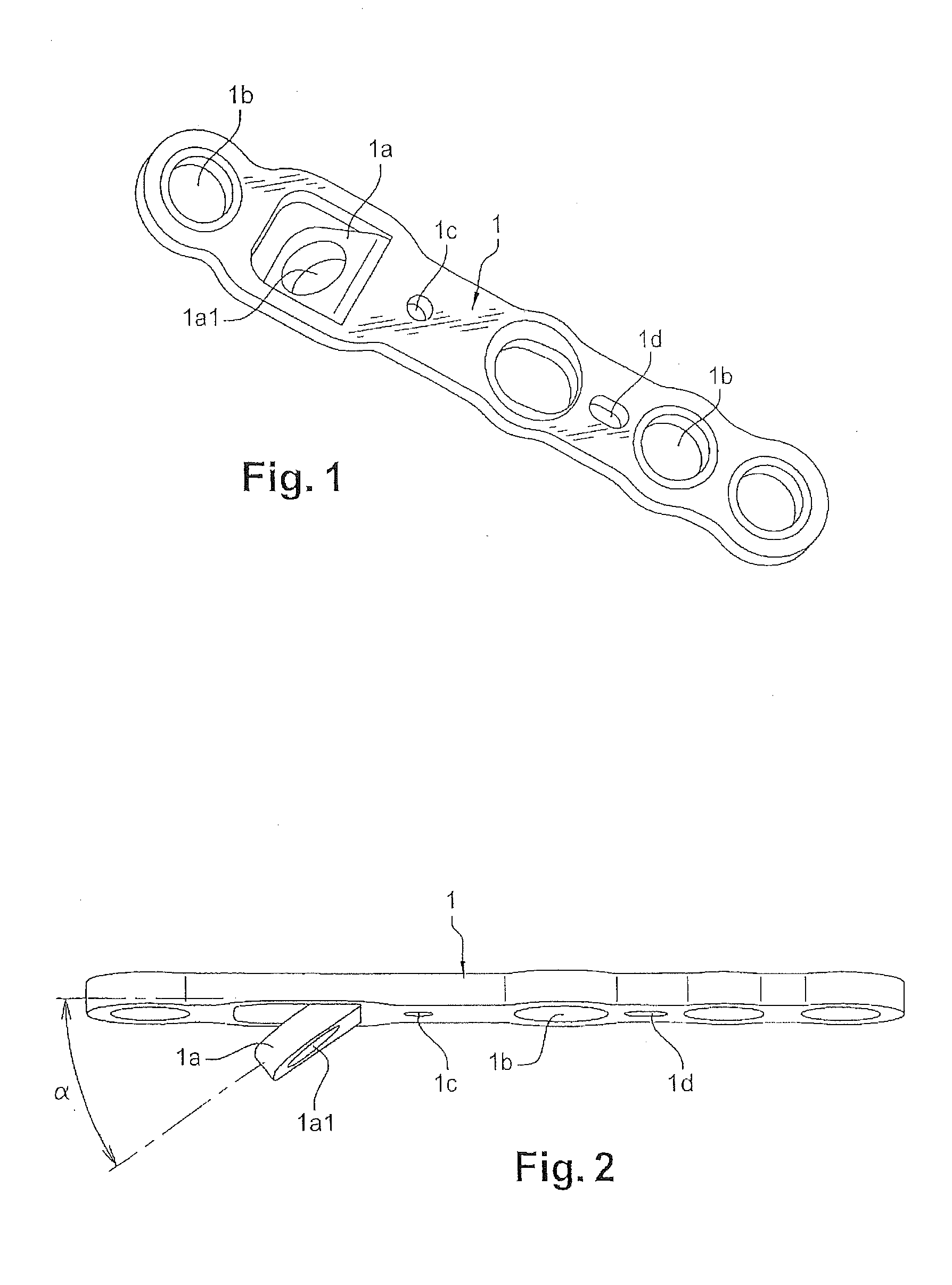
[0011] FIG. 1 is a perspective view of an embodiment of the plate;
[0012] FIG. 2 is a side view of the plate;
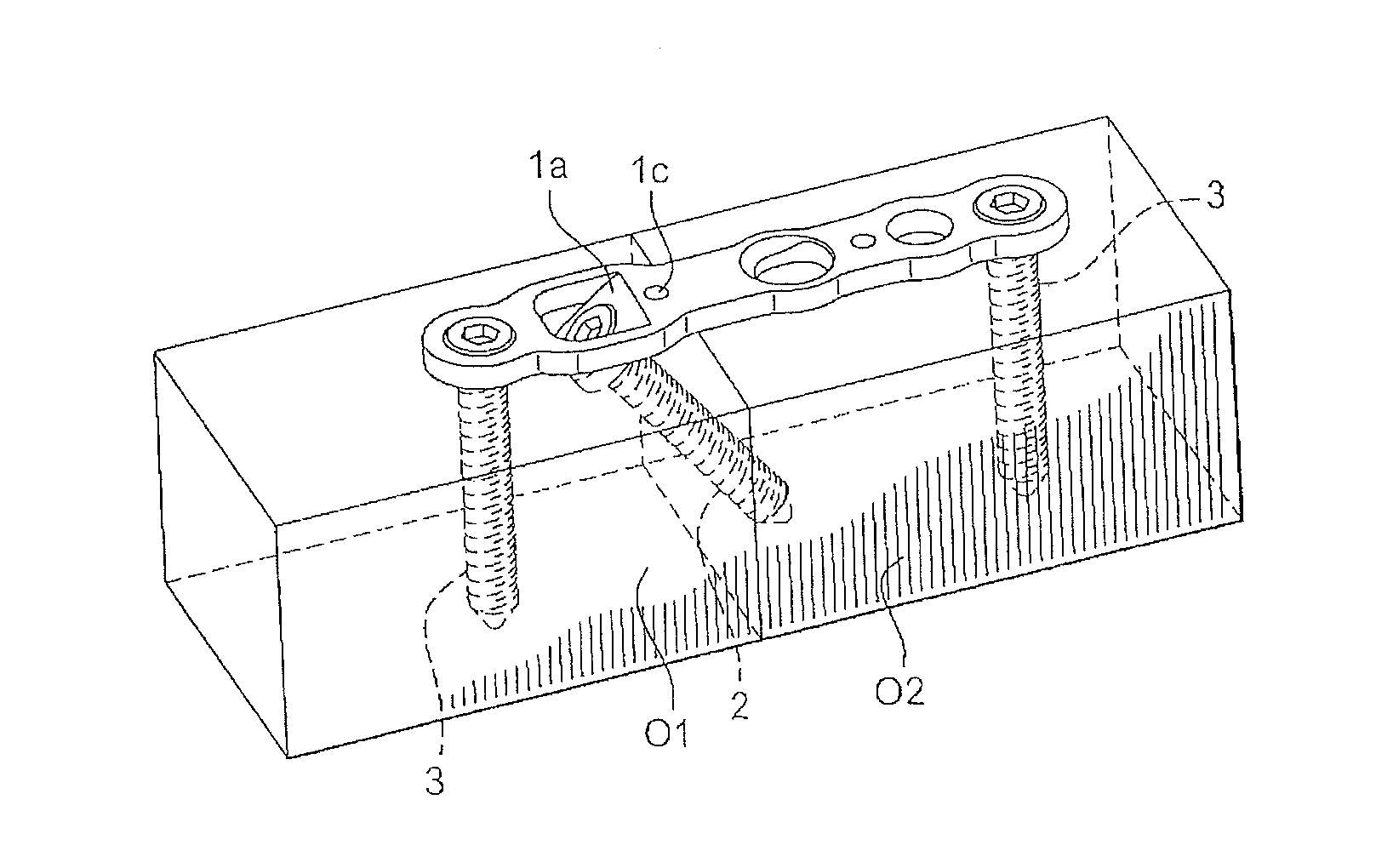
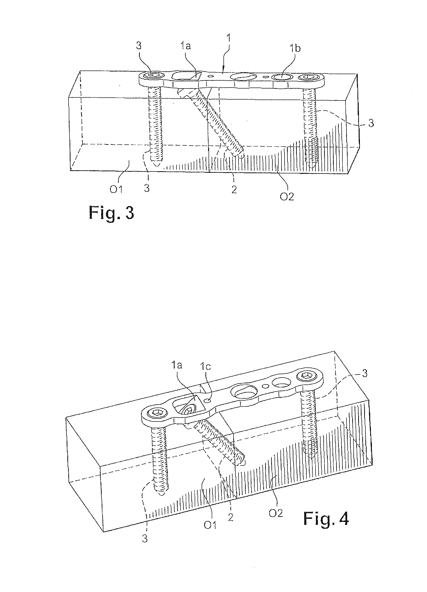
[0013] FIGS. 3 and 4 are perspective views showing the mounting of the plate between two bone parts and their orientation by means of the plate according to the invention, the bone parts being shown schematically.
DETAILED DESCRIPTION
[0014] According to the invention, the plate 1 has at least one formation 1a adapted to enable the positioning of at least one screw 2, at an angle .alpha. of between 30.degree. and 60.degree. with respect to a plane of the plate (FIG. 2).
[0015] In one embodiment, the formation 1a is an angled tab cut out and deformed from the plate. For example, the deformation is made with a cutting-punching operation. This angled tab has a hole 1a1 for screw 2. The angled tab 1a is positioned along the length of the plate so that after the screw 2 is fitted to it, the screw ensures the compression together of the two bone parts, as indicated below in the description.
[0016] In another embodiment, to allow for an angular orientation of the screw 2 according to an angle between about 30.degree. and 60.degree., the formation 1a can be formed as an angled hole. It must be noted that the tab 1a enables adaptation of the angle as a function of the pathology to be treated, given that it is possible to deform this tab at will. In other words, the angle can be adjusted over a few degrees directly by the surgeon in the operating room, using an appropriate tool.
[0017] With reference to FIGS. 3 and 4 that show the positioning of the plate 1 between two bone parts O1 and O2:
[0018] Once the osteotomies have been carried out, a template of the plate, which does not have a guide formation, enables the position of the tab to be determined.
[0019] After determining the position of the tab, the surgeon makes a corresponding recess with the appropriate rasp.
[0020] Once the plate having the tab has been positioned, the surgeon sets one or two screws 3, on a side of the site of the osteosynthesis or the arthrodesis toward the tab. A temporary fastening pin can, possibly, be positioned in a complementary lug.
[0021] The screw 2 is then engaged in the hole 1a1 of the tab 1a to place the fracture in compression.
[0022] Once the compression has been done, the surgeon can screw one or several other additional fastening screws 3 and remove the temporary pin.
[0023] In a known manner, this plate 1 has smooth and/or threaded holes for the fastening screws 3 set in the bone parts O1 and O2 to engage in, as shown in FIGS. 3 and 4.
[0024] Similarly, the plate 1 can have at least one hole 1c for a pin for temporarily positioning the plate 1. Advantageously, the plate 1 can have a guide 1c for the insertion of a pin on the side of one of the bone parts O1 and another guide 1d for the insertion of another pin on the side of the other bone part O2.
[0025] Considering the effect of the desired compression, such as indicated above, the guide 1c is a circular hole whose diameter corresponds substantially to that of the pin, whereas the other guide 1d can be an elongated slot.
[0026] These provisions thus enable the bone to slide under the plate 1 as the screws are set, while ensuring compression along a precise direction, generally axially or parallel to the plate. The pins are of any known and appropriate type, and perfectly known to one having ordinary skill in the art.
[0027] The plate 1 can have several shapes, so that the holes 1a in particular can be aligned or arrayed, all or in part, according to the corners of a triangle or of a quadrilateral. These provisions, in triangle or in quadrilateral, of the screws, improve the stability of the mounting.
[0028] It must be noted also that the plate 1, no matter its shape, can be longitudinally bent so as to adapt to the curvature of the bone, consequently enabling the screws to form an angle between them.
[0029] The advantages are readily apparent from the description.
* * * * *
D00000
D00001
D00002
XML
uspto.report is an independent third-party trademark research tool that is not affiliated, endorsed, or sponsored by the United States Patent and Trademark Office (USPTO) or any other governmental organization. The information provided by uspto.report is based on publicly available data at the time of writing and is intended for informational purposes only.
While we strive to provide accurate and up-to-date information, we do not guarantee the accuracy, completeness, reliability, or suitability of the information displayed on this site. The use of this site is at your own risk. Any reliance you place on such information is therefore strictly at your own risk.
All official trademark data, including owner information, should be verified by visiting the official USPTO website at www.uspto.gov. This site is not intended to replace professional legal advice and should not be used as a substitute for consulting with a legal professional who is knowledgeable about trademark law.