Multi-wavelength Pulse Steering In Lidar Systems
ZHANG; Rui ; et al.
U.S. patent application number 16/283577 was filed with the patent office on 2019-08-29 for multi-wavelength pulse steering in lidar systems. The applicant listed for this patent is Innovusion Ireland Limited. Invention is credited to Junwei BAO, Yimin LI, Rui ZHANG.
| Application Number | 20190265337 16/283577 |
| Document ID | / |
| Family ID | 67685065 |
| Filed Date | 2019-08-29 |
| United States Patent Application | 20190265337 |
| Kind Code | A1 |
| ZHANG; Rui ; et al. | August 29, 2019 |
MULTI-WAVELENGTH PULSE STEERING IN LIDAR SYSTEMS
Abstract
A LiDAR system includes a steering system and a light source. In some cases, the steering system includes a rotatable polygon with reflective sides and/or a dispersion optic. The light source produces light signals, such as light pulses. In some cases, the light sources products light pulses at different incident angles and/or different wavelengths. The steering system scans the light signals. In some cases, the light pulses are scanned based on the wavelength of the light pulses.
| Inventors: | ZHANG; Rui; (Los Altos, CA) ; LI; Yimin; (Los Altos, CA) ; BAO; Junwei; (Los Altos, CA) | ||||||||||
| Applicant: |
|
||||||||||
|---|---|---|---|---|---|---|---|---|---|---|---|
| Family ID: | 67685065 | ||||||||||
| Appl. No.: | 16/283577 | ||||||||||
| Filed: | February 22, 2019 |
Related U.S. Patent Documents
| Application Number | Filing Date | Patent Number | ||
|---|---|---|---|---|
| 62634665 | Feb 23, 2018 | |||
| Current U.S. Class: | 1/1 |
| Current CPC Class: | G01S 17/10 20130101; G01S 7/484 20130101; G01S 7/4815 20130101; G01S 7/4865 20130101; G01S 7/4817 20130101; G01S 7/487 20130101; G01S 7/4818 20130101; G01S 17/42 20130101; G01S 17/89 20130101 |
| International Class: | G01S 7/481 20060101 G01S007/481; G01S 17/10 20060101 G01S017/10; G01S 17/89 20060101 G01S017/89; G01S 7/487 20060101 G01S007/487; G01S 7/486 20060101 G01S007/486; G01S 7/484 20060101 G01S007/484 |
Claims
1. A light detection and ranging (LiDAR) system comprising: a rotatable polygon having a plurality of reflective sides including a first reflective side; a first light source configured to guide a first pulse signal of a first plurality of pulse signals to the first reflective side of the rotatable polygon, the first pulse signal having a first incident angle on the first reflective side and having a first wavelength; and a second light source configured to guide a second pulse signal of a second plurality of pulse signals to the first reflective side of the rotatable polygon, the second pulse signal having a second incident angle on the first reflective side and having a second wavelength.
2. The system of claim 1 further comprising: a mirror configured to scan the first plurality of pulse signals along a first direction and the second plurality of pulse signals along the first direction.
3. The system of claim 1 wherein the first direction is parallel to an axis of rotation for the rotatable polygon.
4. The system of claim 1, wherein a scan area associated with the first plurality of pulses is different than a scan area associated with the second plurality of pulses.
5. The system of claim 1, wherein a scan area associated with the first plurality of pulses does not overlap with a scan area associated with the second plurality of pulses.
6. The system of claim 1, wherein the first pulse has a higher power than the second pulse.
7. The system of claim 1, wherein the first plurality of pulses have a higher repetition rate than the second plurality of pulses.
8. The system of claim 1, wherein the rotatable polygon is configured to scan the first plurality of pulses and the second plurality of pulses in a vertical direction.
9. The system of claim 1, further comprising: a third light source configured to guide a third pulse signal of a third plurality of pulse signals to the first reflective side of the rotatable polygon, the third pulse signal having a third incident angle on the first reflective side and having a third wavelength different than the first wavelength and the second wavelength.
10. The system of claim 1, wherein the first light source includes a first fiber positioned to deliver the first plurality of pulse signals to the rotatable polygon.
11. The system of claim 1, wherein the second light source includes a second fiber positioned to deliver the first plurality of pulse signals to the rotatable polygon.
12. The system of claim 1, wherein the first light source and the second light source share one or more components.
13. The system of claim 1, wherein the first light source and the second light source share are distinct and separate.
14. The system of claim 1, wherein the first and second incident angles are different.
15. The system of claim 1, wherein the first and second incident angles are the same.
16. The system of claim 1, wherein the first and second wavelengths are the same.
17. The system of claim 1, wherein the first and second wavelengths are different.
18. A light detection and ranging (LiDAR) system comprising: a light source configure to produce first plurality of pulses including a first pulse and a second plurality of pulses including a second pulse, wherein the first plurality of pulses have a first wavelength and the second plurality of pulses have a second wavelength different than the first wavelength; and a pulse steering system having a dispersion optic configured to receive along a receive path the first pulse and the second pulse from the light source and to direct the first pulse along a first scan path and the second pulse along a second scan path different than the first scan path.
19. The system of claim 18, wherein the pulse steering system further includes a rotatable polygon having a plurality of reflective sides.
20. The system of claim 19, wherein the rotatable polygon has an axis of rotation parallel to a direction of dispersion of the dispersion optic.
21. The system of claim 18, wherein the pulse steering system further includes a scanning mirror.
22. The system of claim 21, wherein the scanning mirror is a mirror galvanometer.
23. The system of claim 18, wherein the dispersion optic is a prism or an optical grating.
24. The system of claim 18, wherein the light source includes a tunable seed laser.
25. The system of claim 18, wherein the light source includes a fiber configured to deliver the first plurality of light pulses and the second plurality of light pulses to the dispersion optic.
26. The system of claim 18, wherein the light source is further configured to produce a third plurality of pulses, wherein the third plurality of pulses have a third wavelength different than the first wavelength and the second wavelength.
27. The system of claim 18, wherein the light source is configured to provide light pulses of at least 50 different wavelengths.
28. The system of claim 18, wherein the light source is configured to provide light pulses of at least 300 different wavelengths.
29. The system of claim 18, wherein the light source is configured to provide light pulses having wavelengths that differ by less than 1 nm.
Description
CROSS-REFERENCE TO RELATED APPLICATIONS
[0001] This application claims priority to U.S. Provisional Patent Application Ser. No. 62/634,665, filed Feb. 23, 2018, entitled "Multi-wavelength Pulse Steering in LiDAR Systems," the content of which is hereby incorporated by reference for all purposes.
FIELD
[0002] This disclosure relates generally to laser scanning and, more particularly, to using steering pulses in laser scanning systems based on pulse wavelength.
BACKGROUND
[0003] Light detection and ranging (LiDAR) systems use light pulses to create an image or point cloud of the external environment. Some typical LiDAR systems include a light source, a pulse steering system, and light detector. The light source generates light pulses that are directed by the pulse steering system in particular directions when being transmitted from the LiDAR system. When a transmitted light pulse is scattered by an object, some of the scattered light is returned to the LiDAR system as a returned pulse. The light detector detects the returned pulse. Using the time it took for the returned pulse to be detected after the light pulse was transmitted and the speed of light, the LiDAR system can determine the distance to the object along the path of the transmitted light pulse. The pulse steering system can direct light pulses along different paths to allow the LiDAR system to scan the surrounding environment and produce an image or point cloud. LiDAR systems can also use techniques other than time-of-flight and scanning to measure the surrounding environment
SUMMARY
[0004] An embodiment of a LiDAR system includes a rotatable polygon having a plurality of reflective sides including a first reflective side. A first light source guides a first pulse signal of a first plurality of pulse signals to the first reflective side of the rotatable polygon. The first pulse signal has a first incident angle on the first reflective side and having a first wavelength. A second light source guides a second pulse signal of a second plurality of pulse signals to the first reflective side of the rotatable polygon. The second pulse signal has a second incident angle on the first reflective side and having a second wavelength.
[0005] Another embodiment of a LiDAR system includes a light source configure to produce first plurality of pulses including a first pulse and a second plurality of pulses including a second pulse. The first plurality of pulses has a first wavelength and the second plurality of pulse has a second wavelength different than the first wavelength. A pulse steering system includes a dispersion optic configured to receive along a receive path the first pulse and the second pulse from the light source and to direct the first pulse along a first scan path and the second pulse along a second scan path different than the first scan path.
BRIEF DESCRIPTION OF THE DRAWINGS
[0006] The present application can be best understood by reference to the figures described below taken in conjunction with the accompanying drawing figures, in which like parts may be referred to by like numerals.
[0007] FIGS. 1-3 illustrate an exemplary LiDAR system using pulse signal to measure distances to points in the outside environment.
[0008] FIG. 4 depicts a logical block diagram of the exemplary LiDAR system.
[0009] FIG. 5 depicts a light source of the exemplary LiDAR system.
[0010] FIG. 6 depicts a light detector of the exemplary LiDAR system.
[0011] FIGS. 7A-7E depict components for implementing an embodiment of a pulse steering system using light sources producing pulses of different wavelengths.
[0012] FIG. 8 depicts components for implementing an embodiment of a pulse steering system using a dispersion optic to scan pulses in a direction.
[0013] FIG. 9 depicts a portion of the scan pattern generated by the embodiment from FIG. 8.
[0014] FIG. 10 depicts components for implementing another embodiment of a pulse steering system using a dispersion optic to scan pulses in a direction.
[0015] FIG. 11 depicts components for implementing another embodiment of a pulse steering system using a dispersion optic to receive pulses from various directions.
DETAILED DESCRIPTION
[0016] In the following description of examples, reference is made to the accompanying drawings which form a part hereof, and in which it is shown by way of illustration specific examples that can be practiced. It is to be understood that other examples can be used and structural changes can be made without departing from the scope of the disclosed examples.
[0017] Some light detection and ranging (LiDAR) systems using a single light source to produce pulse of a single wavelength that scan the surrounding environment. The pulses are scanned using steering systems direct the pulses in one or two dimensions to cover an area of the surround environment (the scan area). When these systems use mechanical means to direct the pulses, the system complexity increases because more moving parts are required. Additionally, only a single pulse can be emitted at any one time because two or more identical pulses would introduce ambiguity in returned pulses. In some embodiments of the present technology, these disadvantages and/or others are overcome.
[0018] For example, some embodiments of the present technology use two light sources that produce pulses of different wavelengths. These light sources provide the pulses to a pulse steering system at different angles so that the scan area for each light source is different. This allows for tuning the light source to appropriate powers and the possibility of having overlapping scan areas that cover scans of different distances. Longer ranges can be scanned with pulses having higher power and/or slower repetition rate. Shorter ranges can be scanned with pulses having lower power and/or high repetition rate to increase point density.
[0019] As another example, some embodiments of the present technology use pulse steering systems with one or more dispersion elements (e.g., gratings, optical combs, prisms, etc.) to direct pulses based on the wavelength of the pulse. A dispersion element can make fine adjustments to a pulse's optical path, which may be difficult or impossible with mechanical systems. Additionally, using one or more dispersion elements allows the pulse steering system to use few mechanical components to achieve the desired scanning capabilities. This results in a simpler, more efficient (e.g., lower power) design that is potentially more reliable (due to few moving components).
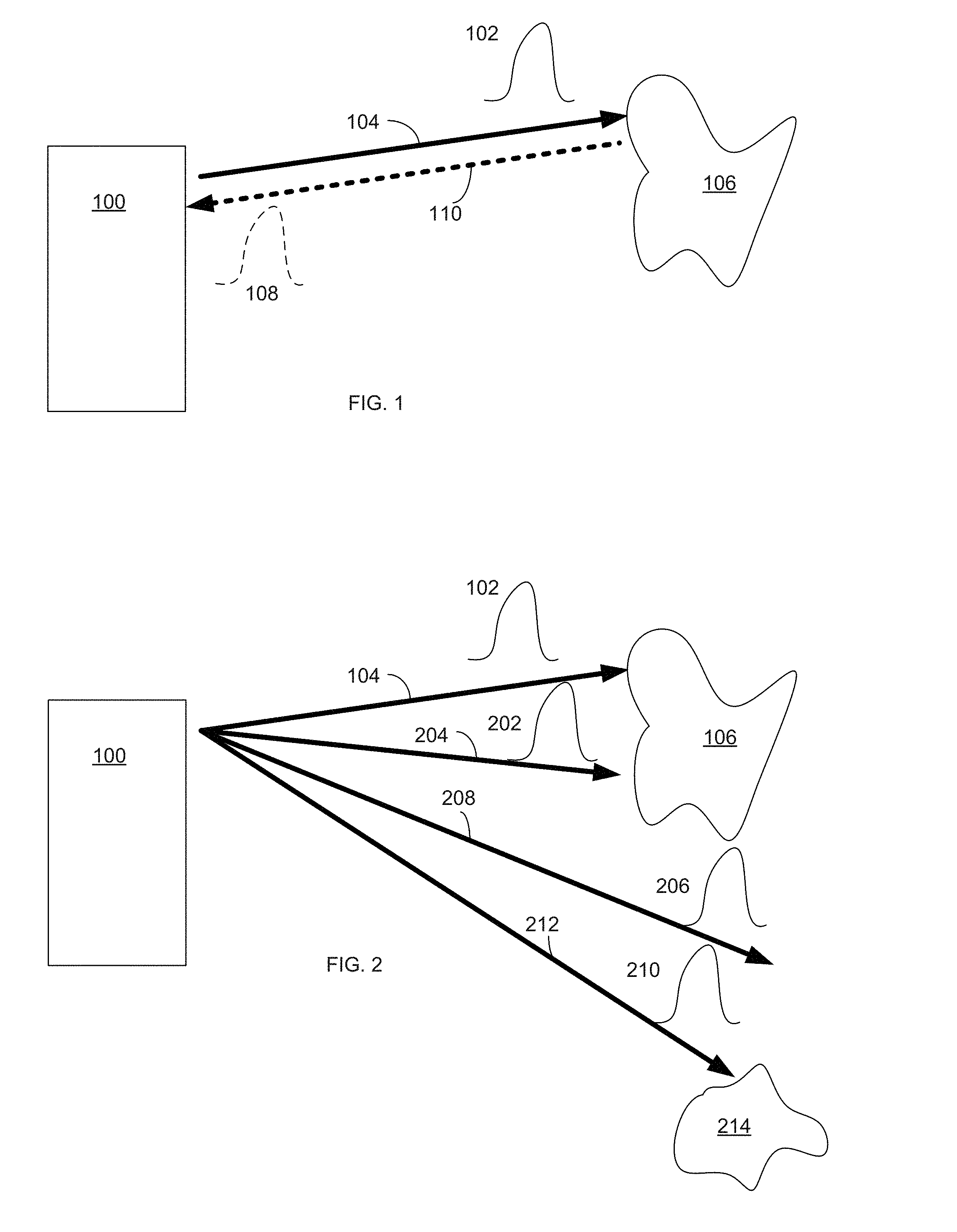
[0020] Some LiDAR systems use the time-of-flight of light signals (e.g., light pulses) to determine the distance to objects in the path of the light. For example, with respect to FIG. 1, an exemplary LiDAR system 100 includes a laser light source (e.g., a fiber laser), a steering system (e.g., a system of one or more moving mirrors), and a light detector (e.g., a photon detector with one or more optics). LiDAR system 100 transmits light pulse 102 along path 104 as determined by the steering system of LiDAR system 100. In the depicted example, light pulse 102, which is generated by the laser light source, is a short pulse of laser light. Further, the signal steering system of the LiDAR system 100 is a pulse signal steering system. However, it should be appreciated that LiDAR systems can operate by generating, transmitting, and detecting light signals that are not pulsed and/use derive ranges to object in the surrounding environment using techniques other than time-of-flight. For example, some LiDAR systems use frequency modulated continuous waves (i.e., "FMCW"). It should be further appreciated that any of the techniques described herein with respect to time-of-flight based systems that use pulses also may be applicable to LiDAR systems that do not use one or both of these techniques.
[0021] Referring back to FIG. 1 (a time-of-flight LiDAR system that uses light pulses) when light pulse 102 reaches object 106, light pulse 102 scatters and returned light pulse 108 will be reflected back to system 100 along path 110. The time from when transmitted light pulse 102 leaves LiDAR system 100 to when returned light pulse 108 arrives back at LiDAR system 100 can be measured (e.g., by a processor or other electronics within the LiDAR system). This time-of-flight combined with the knowledge of the speed of light can be used to determine the range/distance from LiDAR system 100 to the point on object 106 where light pulse 102 scattered.
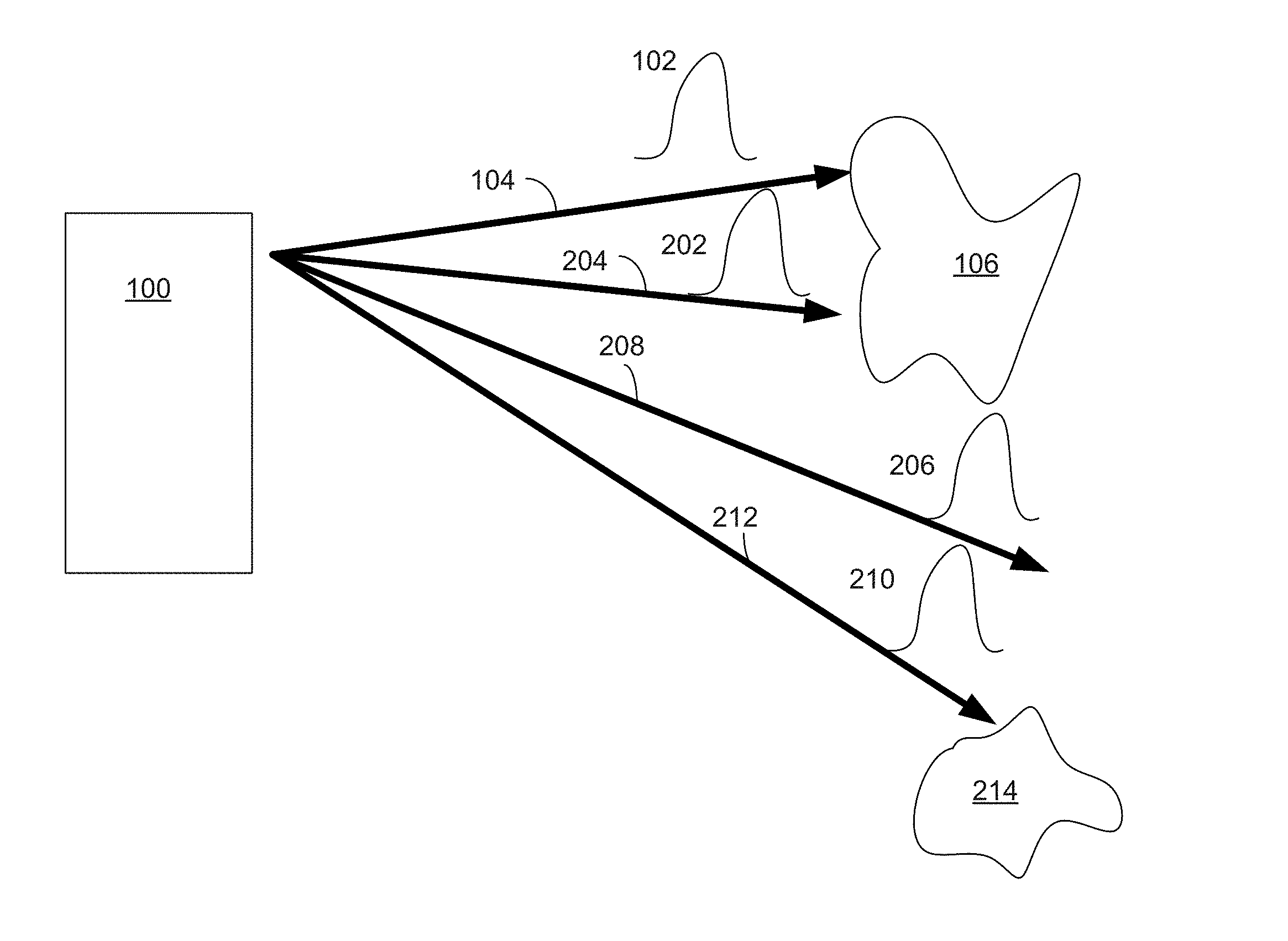
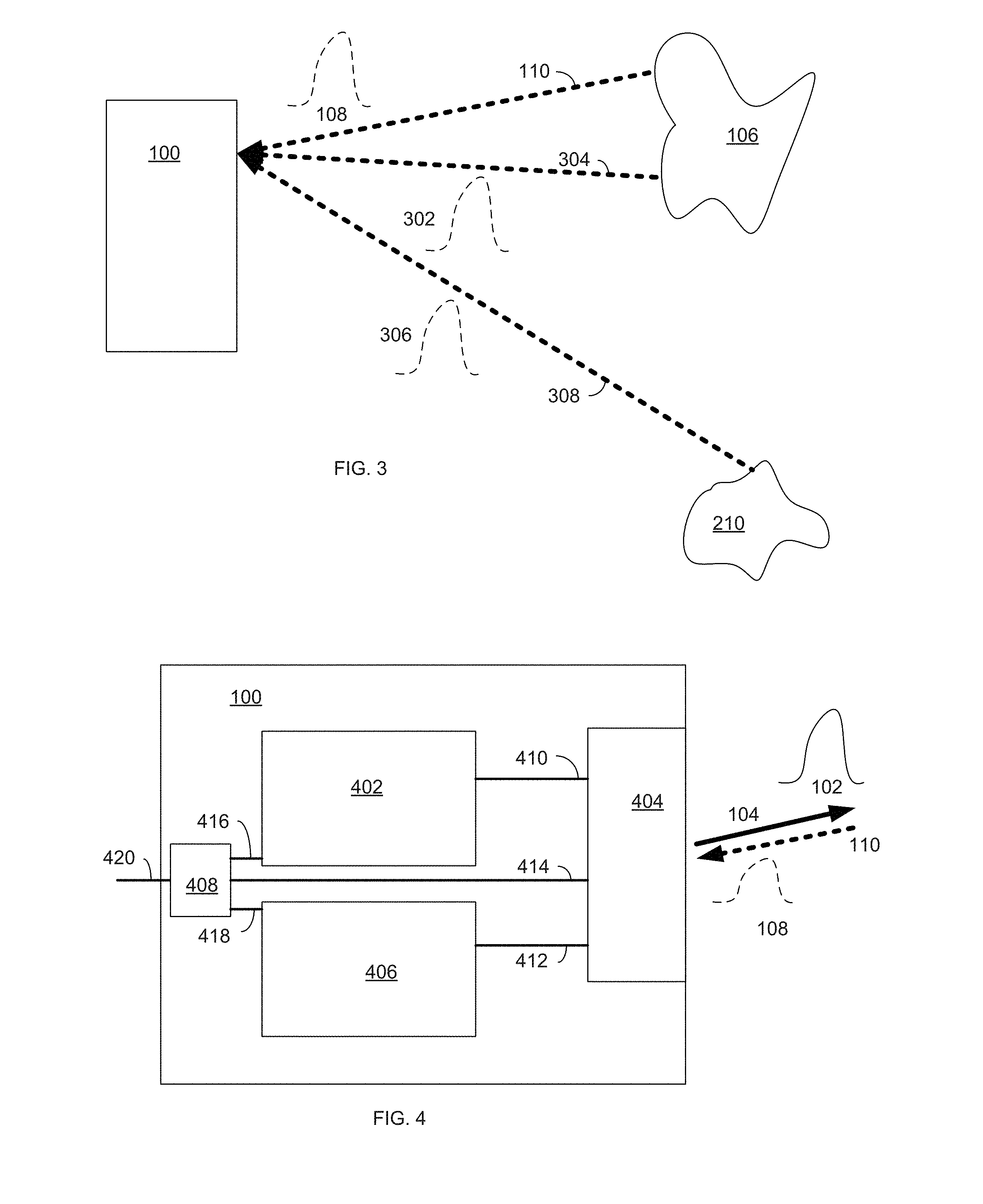
[0022] By directing many light pulses, as depicted in FIG. 2, LiDAR system 100 scans the external environment (e.g., by directing light pulses 102, 202, 206, 210 along paths 104, 204, 208, 212, respectively). As depicted in FIG. 3, LiDAR system 100 receives returned light pulses 108, 302, 306 (which correspond to transmitted light pulses 102, 202, 210, respectively) back after objects 106 and 214 scatter the transmitted light pulses and reflect pulses back along paths 110, 304, 308, respectively. Based on the direction of the transmitted light pulses (as determined by LiDAR system 100) as well as the calculated range from LiDAR system 100 to the points on objects that scatter the light pulses (e.g., the points on objects 106 and 214), the surroundings within the detection range (e.g., the field of view between path 104 and 212, inclusively) can be precisely plotted (e.g., a point cloud or image can be created).
[0023] If a corresponding light pulse is not received for a particular transmitted light pulse, then it can be determined that there are no objects within a certain range of LiDAR system 100 (e.g., the max scanning distance of LiDAR system 100). For example, in FIG. 2, light pulse 206 will not have a corresponding returned light pulse (as depicted in FIG. 3) because it did not produce a scattering event along its transmission path 208 within the predetermined detection range. LiDAR system 100 (or an external system communication with LiDAR system 100) can interpret this as no object being along path 208 within the detection range of LiDAR system 100.
[0024] In FIG. 2, transmitted light pulses 102, 202, 206, 210 can be transmitted in any order, serially, in parallel, or based on other timings with respect to each other. Additionally, while FIG. 2 depicts a 1-dimensional array of transmitted light pulses, LiDAR system 100 optionally also directs similar arrays of transmitted light pulses along other planes so that a 2-dimensional array of light pulses is transmitted. This 2-dimensional array can be transmitted point-by-point, line-by-line, all at once, or in some other manner. The point cloud or image from a 1-dimensional array (e.g., a single horizontal line) will produce 2-dimensional information (e.g., (1) the horizontal transmission direction and (2) the range to objects). The point cloud or image from a 2-dimensional array will have 3-dimensional information (e.g., (1) the horizontal transmission direction, (2) the vertical transmission direction, and (3) the range to objects).
[0025] The density of points in point cloud or image from a LiDAR system 100 is equal to the number of pulses divided by the field of view. Given that the field of view is fixed, to increase the density of points generated by one set of transmission-receiving optics, the LiDAR system should fire a pulse more frequently, in other words, a light source with a higher repetition rate is needed. However, by sending pulses more frequently the farthest distance that the LiDAR system can detect may be more limited. For example, if a returned signal from a distant object is received after the system transmits the next pulse, the return signals may be detected in a different order than the order in which the corresponding signals are transmitted, thereby causing ambiguity if the system cannot correctly correlate the returned signals with the transmitted signals. To illustrate, consider an exemplary LiDAR system that can transmit laser pulses with a repetition rate between 500 kHz and 1 MHz. Based on the time it takes for a pulse to return to the LiDAR system and to avoid mix-up of returned pulses from consecutive pulses in conventional LiDAR design, the farthest distance the LiDAR system can detect may be 300 meters and 150 meters for 500 kHz and 1 MHz, respectively. The density of points of a LiDAR system with 500 kHz repetition rate is half of that with 1 MHz. Thus, this example demonstrates that, if the system cannot correctly correlate returned signals that arrive out of order, increasing the repetition rate from 500 kHz to 1 MHz (and thus improving the density of points of the system) would significantly reduce the detection range of the system.
[0026] FIG. 4 depicts a logical block diagram of LiDAR system 100, which includes light source 402, signal steering system 404, pulse detector 406, and controller 408. These components are coupled together using communications paths 410, 412, 414, 416, and 418. These communications paths represent communication (bidirectional or unidirectional) among the various LiDAR system components but need not be physical components themselves. While the communications paths can be implemented by one or more electrical wires, busses, or optical fibers, the communication paths can also be wireless channels or open-air optical paths so that no physical communication medium is present. For example, in one exemplary LiDAR system, communication path 410 is one or more optical fibers, communication path 412 represents an optical path, and communication paths 414, 416, 418, and 420 are all one or more electrical wires that carry electrical signals. The communications paths can also include more than one of the above types of communication mediums (e.g., they can include an optical fiber and an optical path or one or more optical fibers and one or more electrical wires).
[0027] LiDAR system 100 can also include other components not depicted in FIG. 4, such as power buses, power supplies, LED indicators, switches, etc. Additionally, other connections among components may be present, such as a direct connection between light source 402 and light detector 406 so that light detector 406 can accurately measure the time from when light source 402 transmits a light pulse until light detector 406 detects a returned light pulse.
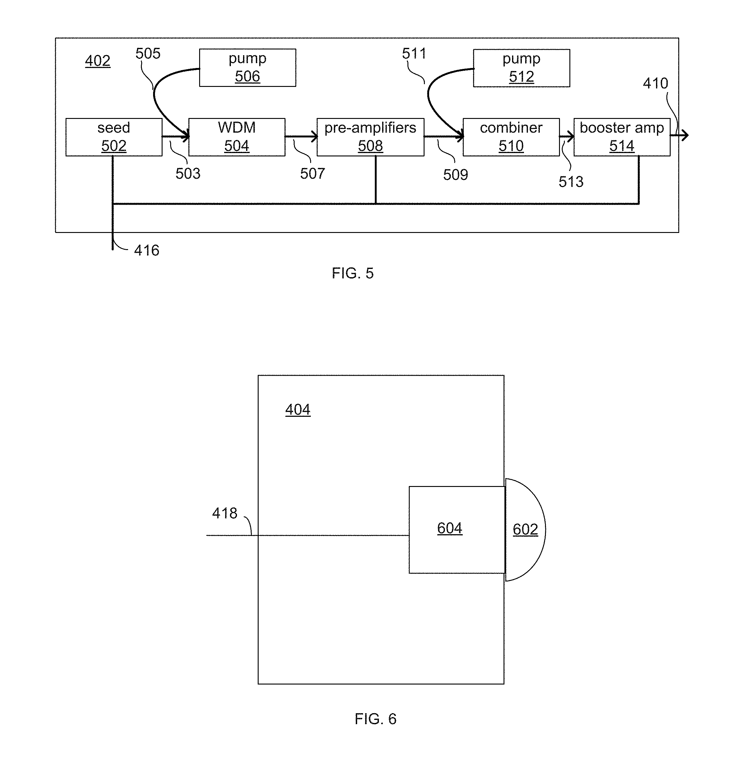
[0028] FIG. 5 depicts a logical block diagram of one example of light source 402 that is based on a laser fiber, although any number of light sources with varying architecture could be used as part of the LiDAR system. Light source 402 uses seed 502 to generate initial light pulses of one or more wavelengths (e.g., 1550 nm), which are provided to wavelength-division multiplexor (WDM) 504 via fiber 503. Pump 506 also provides laser power (of a different wavelength, such as 980 nm) to WDM 504 via fiber 505. The output of WDM 504 is provided to pre-amplifiers 508 (which includes one or more amplifiers) which provides its output to combiner 510 via fiber 509. Combiner 510 also takes laser power from pump 512 via fiber 511 and provides pulses via fiber 513 to booster amplifier 514, which produces output light pulses on fiber 410. The outputted light pulses are then fed to steering system 404. In some variations, light source 402 can produce pulses of different amplitudes based on the fiber gain profile of the fiber used in the source. Communication path 416 couples light source 402 to controller 408 (FIG. 4) so that components of light source 402 can be controlled by or otherwise communicate with controller 408. Alternatively, light source 402 may include its own controller. Instead of controller 408 communicating directly with components of light source 402, a dedicated light source controller communicates with controller 408 and controls and/or communicates with the components of light source 402. Light source 402 also includes other components not shown, such as one or more power connectors, power supplies, and/or power lines.
[0029] Some other light sources include one or more laser diodes, short-cavity fiber lasers, solid-state lasers, and/or tunable external cavity diode lasers, configured to generate one or more light signals at various wavelengths. In some examples, light sources use amplifiers (e.g., pre-amps or booster amps) include a doped optical fiber amplifier, a solid-state bulk amplifier, and/or a semiconductor optical amplifier, configured to receive and amplify light signals.
[0030] Returning to FIG. 4, signal steering system 404 includes any number of components for steering light signals generated by light source 402. In some examples, signal steering system 404 may include one or more optical redirection elements (e.g., mirrors or lens) that steer light pulses (e.g., by rotating, vibrating, or directing) along a transmit path to scan the external environment. For example, these optical redirection elements may include MEMS mirrors, rotating polyhedron mirrors, or stationary mirrors to steer the transmitted pulse signals to different directions. Signal steering system 404 optionally also includes other optical components, such as dispersion optics (e.g., diffuser lenses, prisms, or gratings) to further expand the coverage of the transmitted signal in order to increase the LiDAR system 100's transmission area (i.e., field of view). An example signal steering system is described in U.S. patent application Ser. No. 15/721,127 filed on Sep. 29, 2017, entitled "2D Scanning High Precision LiDAR Using Combination of Rotating Concave Mirror and Beam Steering Devices," the content of which is incorporated by reference in its entirety herein for all purposes. In some examples, signal steering system 404 does not contain any active optical components (e.g., it does not contain any amplifiers). In some other examples, one or more of the components from light source 402, such as a booster amplifier, may be included in signal steering system 404. In some instances, signal steering system 404 can be considered a LiDAR head or LiDAR scanner.
[0031] Some implementations of signal steering systems include one or more optical redirection elements (e.g., mirrors or lens) that steers returned light signals (e.g., by rotating, vibrating, or directing) along a receive path to direct the returned light signals to the light detector. The optical redirection elements that direct light signals along the transmit and receive paths may be the same components (e.g., shared), separate components (e.g., dedicated), and/or a combination of shared and separate components. This means that in some cases the transmit and receive paths are different although they may partially overlap (or in some cases, substantially overlap).
[0032] FIG. 6 depicts a logical block diagram of one possible arrangement of components in light detector 404 of LiDAR system 100 (FIG. 4). Light detector 404 includes optics 604 (e.g., a system of one or more optical lenses) and detector 602 (e.g., a charge coupled device (CCD), a photodiode, an avalanche photodiode, a photomultiplier vacuum tube, an image sensor, etc.) that is connected to controller 408 (FIG. 4) via communication path 418. The optics 604 may include one or more photo lenses to receive, focus, and direct the returned signals. Light detector 404 can include filters to selectively pass light of certain wavelengths. Light detector 404 can also include a timing circuit that measures the time from when a pulse is transmitted to when a corresponding returned pulse is detected. This data can then be transmitted to controller 408 (FIG. 4) or to other devices via communication line 418. Light detector 404 can also receive information about when light source 402 transmitted a light pulse via communication line 418 or other communications lines that are not shown (e.g., an optical fiber from light source 402 that samples transmitted light pulses). Alternatively, light detector 404 can provide signals via communication line 418 that indicate when returned light pulses are detected. Other pulse data, such as power, pulse shape, and/or wavelength, can also be communicated.
[0033] Returning to FIG. 4, controller 408 contains components for the control of LiDAR system 100 and communication with external devices that use the system. For example, controller 408 optionally includes one or more processors, memories, communication interfaces, sensors, storage devices, clocks, ASICs, FPGAs, and/or other devices that control light source 402, signal steering system 404, and/or light detector 406. In some examples, controller 408 controls the power, rate, timing, and/or other properties of light signals generated by light source 402; controls the speed, transmit direction, and/or other parameters of light steering system 404; and/or controls the sensitivity and/or other parameters of light detector 406.
[0034] Controller 408 optionally is also configured to process data received from these components. In some examples, controller determines the time it takes from transmitting a light pulse until a corresponding returned light pulse is received; determines when a returned light pulse is not received for a transmitted light pulse; determines the transmitted direction (e.g., horizontal and/or vertical information) for a transmitted/returned light pulse; determines the estimated range in a particular direction; and/or determines any other type of data relevant to LiDAR system 100.
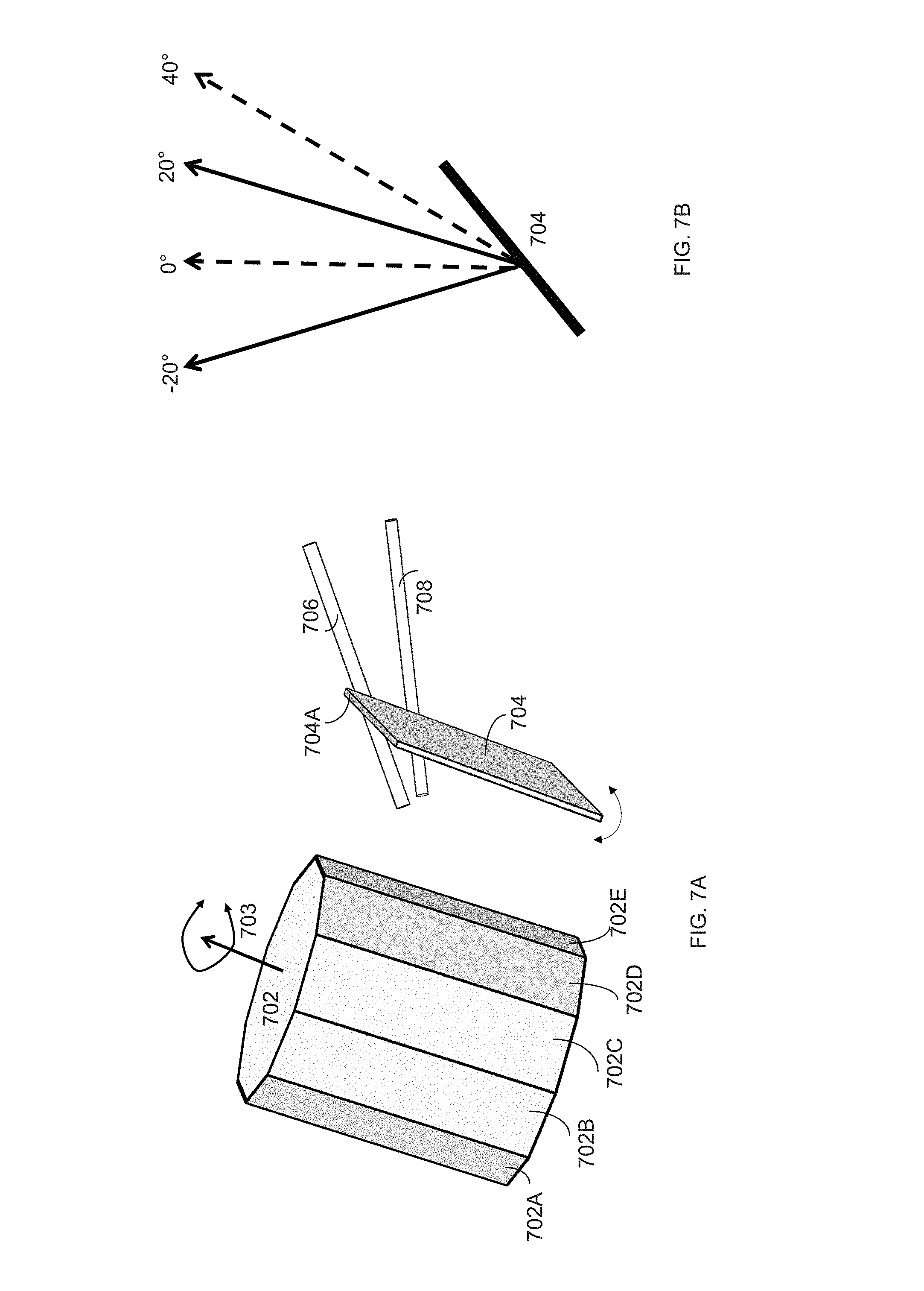
[0035] FIG. 7A depicts part of a pulse steering system (e.g., pulse steering system 404 of FIG. 4) according to some embodiments of the present technology. Polygon 702 has ten reflective sides (sides 702A-702E are visible in FIG. 7A) but can have any number of reflective sides. Polygon 702 rotates about axis 703 based on a drive motor (not shown) to scan pulses from fiber 706 and 708 along a direction perpendicular to axis of rotation 703 (see FIGS. 7C-7E).
[0036] Mirror 704 is positioned next to polygon 702 so that pulses emitted from fiber 706 and 708 that are reflected off rotating polygon 702 are reflected again along a desired optical path. Mirror 704 tilts so as to scan pulses from fiber 706 and 708 in a direction different than the direction that polygon 702 scans pulses (e.g., edge 704A tilts towards and away from polygon 702 so as to scan pulses along a path that is parallel to the axis of rotation of polygon 702). In some examples, polygon 702 is responsible for scanning pulses in the vertical direction of the LiDAR system and mirror 704 is responsible for scanning pulses in the horizontal direction. In some other examples, polygon 702 and mirror 704 are configured in the reverse manner.
[0037] In some cases, fiber 706 and fiber 708 provide pulses of different wavelengths (e.g., fiber 706 only provides pulses of a wavelength that is different than the wavelength of pulses provided from fiber 708). For example, the fibers may be connected to different light sources that are designed/tuned to provide pulses of different wavelengths or the fibers may be connected to the same light source that is capable of producing pulses of different wavelengths). In some systems, the power for pulses of each wavelength are tuned based on the distances anticipated in the scan area covered by those pulses. In other cases, fiber 706 and fiber 708 provide light signals of the same wavelength (e.g., fiber 706 and fiber 708 are connected to the same light source that only provides one wavelength). Fiber 706 and fiber 708 are positioned to provide their respective pulses to polygon 702 at different incident angles, which results in the pulses having different reflection angles from polygon 702. This causes the scan area provided by the pulses from the two fibers to have different scan areas, as illustrated in the example of FIG. 7B. Because fiber 706 and fiber 708 are positioned to provide pulses at different angle to polygon 702, the scan areas (the scan area for fiber 706 is represented by the two dotted lines and the scan area for fiber 708 is represented by the two solid lines) are also different. In FIG. 7B, the scan areas overlap. In some other embodiments, the scan areas do not overlap.
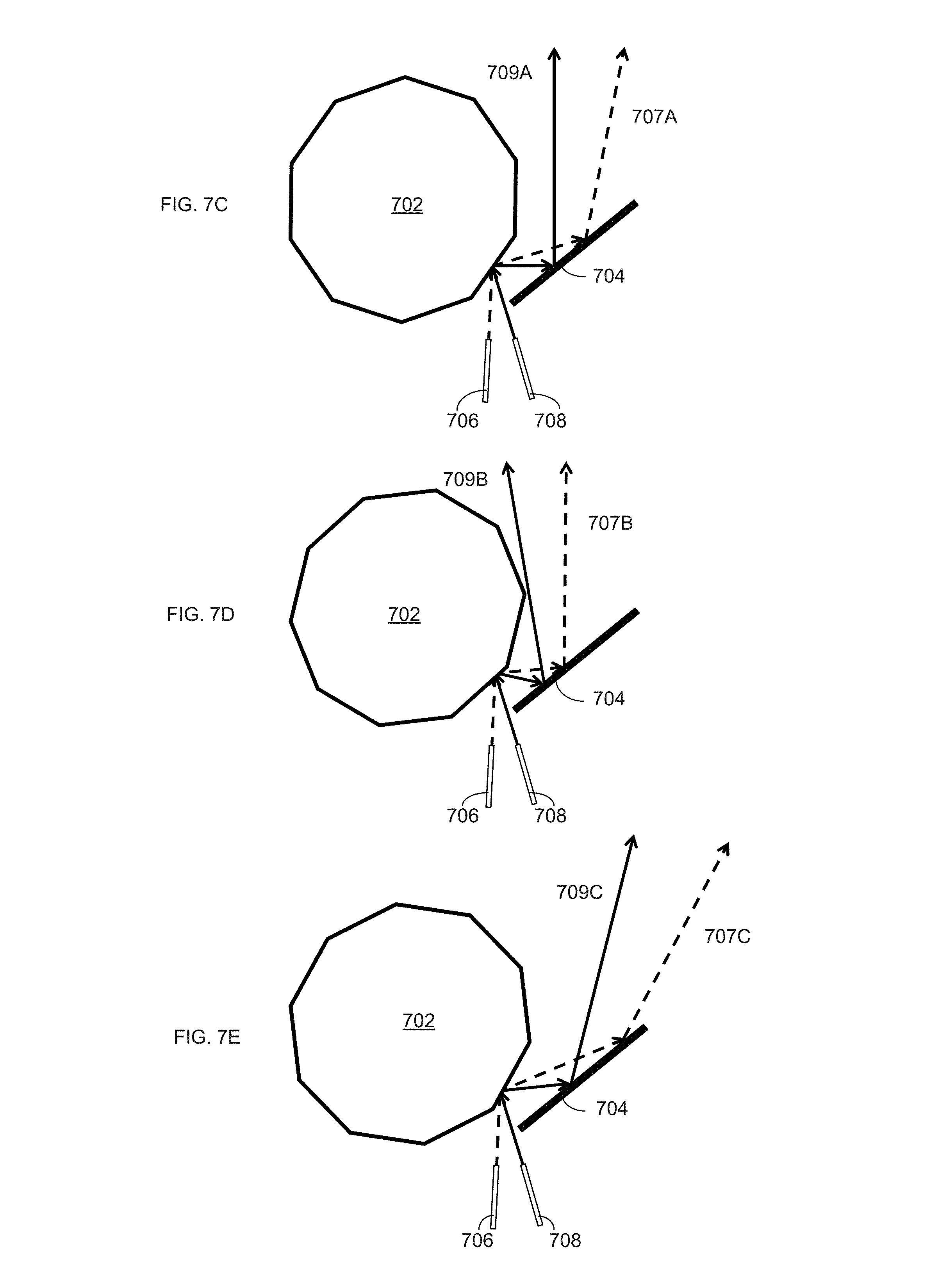
[0038] FIGS. 7C-7E further illustrate the different scan areas produced by fiber 706 versus fiber 708. In FIG. 7C, fiber 706 and 708 are configured to provide pulses to polygon 702 at different incident angles. The rotation of polygon 702 allows for the scanning of the pulses in a direction perpendicular to the axis of rotation (which is perpendicular to the page in FIGS. 7C-7E). When polygon 702 is in the position depicted in FIG. 7C, pulses from fiber 706 will be directed along optical path 707A while pulses from fiber 708 will be directed along optical path 709A. When polygon 702 is in the position depicted in FIG. 7D, pulses from fiber 706 will be directed along optical path 707B while pulses from fiber 708 will be directed along optical path 709B. When polygon 702 is in the position depicted in FIG. 7E, pulses from fiber 706 will be directed along optical path 707C while pulses from fiber 708 will be directed along optical path 709C.
[0039] Because pulses from fiber 706 and fiber 708 have different wavelengths, they can be triggered without regard to each other (e.g., triggered at the same time, in close proximity to each other, at different rates, at the same rate, synchronously, asynchronously, etc.). The wavelength of a returned pulse will indicate to the LiDAR system along which optical path the pulse traveled. The pulses of each fiber can have other different properties as well. For example, pulses from fiber 706 might have a slow repetition rate but have a higher power. These pulses, in some cases, are more suited for detecting ranges of far away objects but at a lower resolution (e.g., lower density of points). In this example, pulses form fiber 708 might have a high repetition rate but have lower power, and are more suited for detecting ranges to nearby objects with higher resolution (e.g., more points).
[0040] While the example in FIGS. 7A-7E uses two fibers providing pulses of two different wavelengths, more fibers and/or wavelengths can be used. For example, if another fiber at a different angle is use, a third scan area can be added to the areas depicted in FIG. 704. This scan area can overlap with completely, partly, or not at all with the scan areas produced by pulses form fibers 706 and 708.
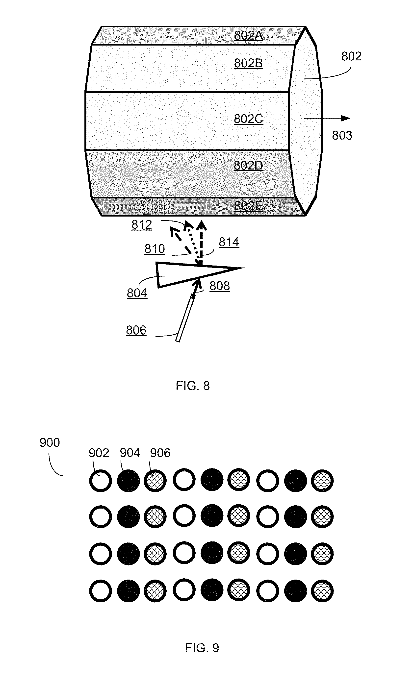
[0041] FIG. 8 depicts part of a pulse steering system (e.g., pulse steering system 404 of FIG. 4) according to some embodiments of the present technology. Polygon 802 has ten reflective sides (sides 802A-802E are visible in FIG. 8) but can have any number of reflective sides. Polygon 802 rotates about axis 803 based on a drive motor (not shown) to scan pulses from fiber 806 along a direction perpendicular to axis of rotation 803 (similar to the scanning of polygon 702 in FIGS. 7A-7E).
[0042] In the example in FIG. 8, fiber 806 provides pulses of different wavelengths along path 808 to a dispersion optic (prism 804 in FIG. 8 but other dispersion optics can be used, such as gratings). The dispersion optic directs pulses along different optical paths (e.g., one of paths 810, 812, or 814) according to the wavelength of the pulse. In this manner, the dispersion optic can scan pulses along a direction (e.g., a direction parallel to axis of rotation 803, which is also the direction of dispersion) without using any moving parts. Additional scanning components (e.g., a mirror similar to mirror 704 of FIGS. 7A-7E) can be used to expand the scan pattern further in the same direction. Prism 804 (or other dispersion optics) allows for fine separation of pulses that can be used to decrease the speed of the rotating polygon 802 by allowing for more scan lines in the given amount of time.
[0043] FIG. 9 depicts an example scan pattern 900 that could be generated using the configuration depicted in FIG. 8. Empty circles (e.g., circle 902) represent pulses having a wavelength that travels on path 810. Solid circles (e.g., circle 904) represent pulses having a wavelength that travels on path 812. Cross-hatched circles (e.g., circle 906) represent pulses having a wavelength that travels on path 814. The horizontal separation of these three pulses is due to the dispersion optic. The horizontal repetition of this pattern of three pulses is due to additional scanning components in the pulse steering system (e.g., mirror 704 of FIG. 7A-7E). The vertical repetition of the pattern is due rotating polygon 802.
[0044] By using dispersion element 804 with pulses of different wavelengths, as depicted in FIG. 8, a pulse steering system can realize several benefits. For example, the dispersion element can provide for a higher density scan pattern that possible with mechanical-only scanning. It may also provide for the ability to scan the pattern faster than mechanical-only scanning can.
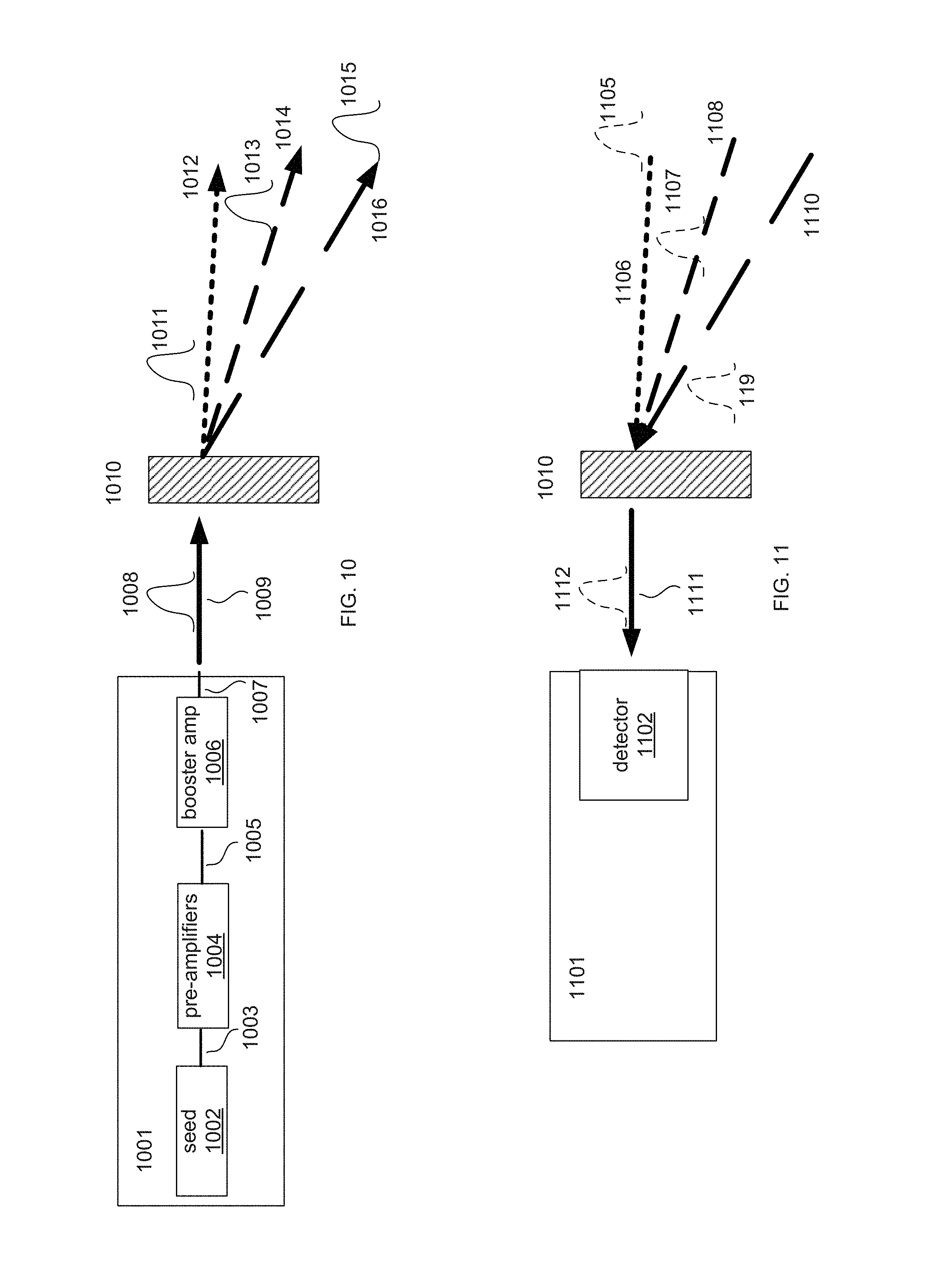
[0045] FIGS. 10 and 11 depict parts of a LiDAR system according to some embodiments of the present invention. In FIG. 10, light source 1001 has laser seed 1002 connected to pre-amplifier 1004 via fiber 1003. Pre-amplifier 1004 is connected to amplifier 1006 via fiber 1005. Output pulses are provided on output 1007, which can be any number of optical outputs, such as a fiber. Laser seed 1002 is a tunable laser seed (such as external-cavity diode lasers and distributed Bragg reflector lasers). It can produce pulses with different wavelengths. In some examples, laser seed 1002 provides pulses with wavelengths ranging from 1510 nm to 1580 nm. The pulses of various wavelengths from light source 1001, such as pulse 1008, are provided along path 1009 to a dispersion element (in FIG. 10, the dispersion optics is grating 1010, but other dispersion optics can be used) that is part of a pulse steering system (which optically includes one or more additional optics). Based on the wave length of the pulse, the dispersion optic directs the pulse along any number of paths. For example, because pulses 1011, 1013, and 1015 are each a different wavelength, the dispersion optic directs the pulses down a path associated with the wavelength, path 1012, path 1014, and 1016, respectively. The dispersion optic performs this function based on the wavelength dependence of its refractive index. By sweeping the wavelength of seed 1002 while producing pulses, a LiDAR system can scan pulses along a line using a dispersion optic. Additional components (e.g., moving mirrors and/or polygons described above) can be used to expand the scan pattern to two dimensions.
[0046] FIG. 11 depicts a portion of the receive path of the LiDAR system from FIG. 10. In FIG. 11, return pulses 1105, 1107, and 1109 associated with pulses 1011, 1013, and 1015 (FIG. 10), respectively, travel along optical paths 1106, 1108, and 1110, respectively, back to the dispersion optic. Optical paths 1106, 1108, and 1110 are similar or the same as optical path 1012, path 1014, and 1016, respectively. Dispersion optic redirects return pulses 1105, 1107, and 1109 along optical path 1111 (similar to return pulse 1112) so that detector 1102 of light detector 1101 can detect the return pulses and LiDAR system can calculate ranges associated with the pulses.
[0047] Various exemplary embodiments are described herein. Reference is made to these examples in a non-limiting sense. They are provided to illustrate more broadly applicable aspects of the disclosed technology. Various changes may be made and equivalents may be substituted without departing from the true spirit and scope of the various embodiments. In addition, many modifications may be made to adapt a particular situation, material, composition of matter, process, process act(s) or step(s) to the objective(s), spirit or scope of the various embodiments. Further, as will be appreciated by those with skill in the art, each of the individual variations described and illustrated herein has discrete components and features which may be readily separated from or combined with the features of any of the other several embodiments without departing from the scope or spirit of the various embodiments.
* * * * *
D00000
D00001
D00002
D00003
D00004
D00005
D00006
D00007
XML
uspto.report is an independent third-party trademark research tool that is not affiliated, endorsed, or sponsored by the United States Patent and Trademark Office (USPTO) or any other governmental organization. The information provided by uspto.report is based on publicly available data at the time of writing and is intended for informational purposes only.
While we strive to provide accurate and up-to-date information, we do not guarantee the accuracy, completeness, reliability, or suitability of the information displayed on this site. The use of this site is at your own risk. Any reliance you place on such information is therefore strictly at your own risk.
All official trademark data, including owner information, should be verified by visiting the official USPTO website at www.uspto.gov. This site is not intended to replace professional legal advice and should not be used as a substitute for consulting with a legal professional who is knowledgeable about trademark law.