Substrate Processing Apparatus, Substrate Processing Method, And Storage Medium Storing Program
ISHII; Yu ; et al.
U.S. patent application number 16/224537 was filed with the patent office on 2019-06-20 for substrate processing apparatus, substrate processing method, and storage medium storing program. The applicant listed for this patent is EBARA CORPORATION. Invention is credited to Yu ISHII, Yu MACHIDA.
| Application Number | 20190184517 16/224537 |
| Document ID | / |
| Family ID | 66813745 |
| Filed Date | 2019-06-20 |


View All Diagrams
| United States Patent Application | 20190184517 |
| Kind Code | A1 |
| ISHII; Yu ; et al. | June 20, 2019 |
SUBSTRATE PROCESSING APPARATUS, SUBSTRATE PROCESSING METHOD, AND STORAGE MEDIUM STORING PROGRAM
Abstract
A substrate processing apparatus includes: a first polishing head configured to polish a first surface of a substrate by sliding a polishing tool on the first surface; a second polishing head configured to polish the first surface of the substrate by sliding a polishing tool on the first surface, the second polishing head having a smaller diameter than a diameter of the first polishing head; and a substrate support mechanism configured to support the substrate by a fluid pressure at positions corresponding to the first polishing head and the second polishing head, the substrate support mechanism being configured to support the substrate from a second surface of the substrate opposite to the first surface.
| Inventors: | ISHII; Yu; (Tokyo, JP) ; MACHIDA; Yu; (Tokyo, JP) | ||||||||||
| Applicant: |
|
||||||||||
|---|---|---|---|---|---|---|---|---|---|---|---|
| Family ID: | 66813745 | ||||||||||
| Appl. No.: | 16/224537 | ||||||||||
| Filed: | December 18, 2018 |
| Current U.S. Class: | 1/1 |
| Current CPC Class: | B24B 7/04 20130101; B24B 27/04 20130101; B24B 37/005 20130101; B24B 41/061 20130101; B24B 27/0076 20130101; B24B 41/067 20130101; B24B 21/06 20130101; B24B 21/004 20130101; B24B 37/042 20130101; B24B 37/10 20130101; B24B 7/228 20130101 |
| International Class: | B24B 37/04 20060101 B24B037/04; B24B 37/005 20060101 B24B037/005; B24B 37/10 20060101 B24B037/10 |
Foreign Application Data
| Date | Code | Application Number |
|---|---|---|
| Dec 20, 2017 | JP | 2017-244060 |
Claims
1. A substrate processing apparatus comprising: a first polishing head configured to polish a first surface of a substrate by sliding a first polishing tool on the first surface; a second polishing head configured to polish the first surface of the substrate by sliding a second polishing tool on the first surface, the second polishing head having a smaller diameter than a diameter of the first polishing head; and a substrate support mechanism configured to support the substrate by a fluid pressure at positions corresponding to the first polishing head and the second polishing head from a second surface of the substrate opposite to the first surface.
2. The substrate processing apparatus according to claim 1, wherein the substrate support mechanism includes: a first static pressure plate configured to support the substrate at the position corresponding to the first polishing head; and a second static pressure plate configured to support the substrate at the position corresponding to the second polishing head.
3. The substrate processing apparatus according to claim 2, further comprising: a second arm configured to move the second polishing head; a movable mechanism provided in the substrate support mechanism and configured to move the second static pressure plate; and a controller configured to control the second arm and the movable mechanism such that the second static pressure plate follows the second polishing head.
4. The substrate processing apparatus according to claim 1, wherein the substrate support mechanism includes: a static pressure plate; and a movable mechanism configured to move the static pressure plate between an area corresponding to the first polishing head and an area corresponding to the second polishing head.
5. The substrate processing apparatus according to claim 1, wherein the substrate support mechanism includes: a static pressure plate configured to support the substrate at the positions corresponding to the first polishing head and the second polishing head; a first fluid line configured to supply a fluid to an area on the static pressure plate corresponding to the first polishing head; and a second fluid line configured to supply a fluid to an area on the static pressure plate corresponding to the second polishing head.
6. The substrate processing apparatus according to claim 5, further comprising: a second arm configured to move the second polishing head; a plurality of the second fluid line provided in the substrate support mechanism and connected with a plurality of positions on the static pressure plate within a range in which the second polishing head is moved; and a controller configured to control an amount of the fluid to be supplied through each second fluid line, thereby to change positions on the static pressure plate to which the fluid is supplied follows the second polishing head.
7. The substrate processing apparatus according to claim 1, wherein the second polishing head is arranged to polish the substrate at a position outside of the first polishing head in a radial direction of the substrate.
8. The substrate processing apparatus according to claim 1, wherein the substrate processing apparatus includes a back surface polishing apparatus, the first surface of the substrate is a surface on which no device is formed, and the polishing process is performed after a resist is applied to the second surface of the substrate and before an exposure process is performed.
9. A substrate processing apparatus comprising: a substrate holding mechanism configured to hold and rotate a substrate, the substrate holding mechanism including a plurality of rollers configured to be able to contact a periphery of the substrate, each roller being configured to be rotatable about an axis thereof; a first polishing head configured to polish a first surface of the substrate by sliding a first polishing tool on the first surface; and a second polishing head configured to polish the first surface of the substrate by sliding a second polishing tool on the first surface, the second polishing head having a smaller diameter than a diameter of the first polishing head.
10. A substrate processing method comprising: polishing a first surface of a substrate by sliding a first polishing tool of a first polishing head on the first surface of the substrate and by sliding a second polishing tool of a second polishing head on the first surface of the substrate, the second polishing head having a smaller diameter than a diameter of the first polishing head; and supporting the substrate from a second surface of the substrate at positions corresponding to the first polishing head and the second polishing head, the second surface being opposite to the first surface.
11. The substrate processing method according to claim 10, wherein the first surface of the substrate is a surface on which no device is formed, and the polishing process is performed after a resist is applied to the second surface of the substrate and before an exposure process is performed.
12. A substrate processing method comprising: rotating a substrate by bringing a plurality of rollers into contact with a periphery of the substrate and rotating each roller about an axis thereof; and polishing, during rotation of the substrate, a first surface of the substrate with a first polishing head and a second polishing head, the second polishing head having a smaller diameter than a diameter of the first polishing head.
13. The substrate processing method according to claim 12, wherein the first surface of the substrate is a surface on which no device is formed, and the polishing process is performed after a resist is applied to the second surface of the substrate and before an exposure process is performed.
14. A non-volatile storage medium storing a program causing a computer to perform a method for controlling a substrate processing apparatus, the method comprising: polishing a first surface of a substrate by sliding a first polishing tool of a first polishing head on the first surface of the substrate and by sliding a second polishing tool of a second polishing head on the first surface of the substrate, the second polishing head having a smaller diameter than a diameter of the first polishing head; and supporting, during the polishing, the substrate from a second surface of the substrate at positions corresponding to the first polishing head and the second polishing head, the second surface being opposite to the first surface.
15. A non-volatile storage medium storing a program causing a computer to perform a method for controlling a substrate processing apparatus, the method comprising: rotating a substrate by bringing a plurality of rollers into contact with a periphery of the substrate and rotating each roller about an axis thereof; and polishing, during rotation of the substrate, a first surface of the substrate with a first polishing head and a second polishing head, the second polishing head having a smaller diameter than a diameter of the first polishing head.
Description
TECHNICAL FIELD
[0001] The present invention relates to a substrate processing apparatus, a substrate processing method, and a storage medium storing a program causing a computer to perform the method for controlling a substrate processing apparatus.
BACKGROUND ART
[0002] In recent years, devices such as a memory circuit, a logic circuit and an image sensor (e.g., CMOS sensor) have been more highly integrated. During fabrication of these devices, foreign materials such as particulates and dust may adhere to the device. Foreign materials adhered to the device may cause a short circuit between wires or a failure of the circuit. Therefore, in order to improve reliability of the device, it is required to clean the wafer on which the device is fabricated to remove foreign materials on the wafer.
[0003] The above foreign materials such as particulates and dust may also adhere to the back surface (non-device surface) of the wafer. Adhesion of these foreign materials on the back surface of the wafer may cause the wafer to be separated from a reference plane of the stage of an exposure device or may cause the front surface of the wafer to be inclined relative to the reference plane of the stage. This results in a patterning deviation or a deviation of a focal distance. To prevent these problems, foreign materials adhered to the back surface of the wafer need to be removed after a resist is applied to the front surface (device surface) of the wafer and before an exposure process is performed on the front surface.
[0004] A patterning device using nano-imprinting technology has recently been developed, besides one using optical exposure technology. The nano-imprinting technology is a technology in which a patterning die is pressed against a resin material applied to the wafer and thereby a wiring pattern is transferred. The nano-imprinting technology requires removal of foreign materials present on the front surface of the wafer in order to prevent dirt from being transferred between the die and the wafer and between the wafers.
[0005] PTL 1 discloses a substrate processing apparatus that removes foreign materials adhered to the front surface and/or the back surface of the wafer by sliding a scrubber including abrasive grains, a polishing tape or the like on the rotating wafer.
CITATION LIST
Patent Literature
[0006] PTL 1: Japanese Patent Laid-Open No. 2013-172019
SUMMARY OF INVENTION
Technical Problem
[0007] However, polishing the substrate with a relatively large polishing head alone may result in local areas of the substrate being insufficiently polished. For example, an outer periphery of the substrate contacts a polishing tool of the polishing head for a shorter time than a central part of the substrate, and thus the outer periphery tends to have a lower polishing rate. This variation in the polishing rate may decrease in-plane uniformity of the substrate and affect an exposure process. An object of the present invention is to solve at least a part of the above problems.
Solution to Problem
[0008] According to an aspect of the present invention, a substrate processing apparatus includes: a first polishing head configured to polish a first surface of a substrate by sliding a polishing tool on the first surface; a second polishing head configured to polish the first surface of the substrate by sliding a polishing tool on the first surface, the second polishing head having a smaller diameter than a diameter of the first polishing head; and a substrate support mechanism configured to support the substrate by a fluid pressure at positions corresponding to the first polishing head and the second polishing head from a second surface of the substrate opposite to the first surface.
[0009] According to another aspect of the present invention, a substrate processing apparatus includes: a substrate holding mechanism configured to hold and rotate a substrate, the substrate holding mechanism including plural rollers configured to be able to contact a periphery of the substrate, each roller being configured to be rotatable about an axis thereof; a first polishing head configured to polish a first surface of the substrate by sliding a polishing tool on the first surface; and a second polishing head configured to polish the first surface of the substrate by sliding a polishing tool on the first surface, the second polishing head having a smaller diameter than a diameter of the first polishing head.
BRIEF DESCRIPTION OF DRAWINGS
[0010] FIG. 1 is a plan view of a substrate processing system including a substrate processing apparatus according to one embodiment.
[0011] FIG. 2A is a schematic plan view of a configuration of a polishing head of a polishing unit.
[0012] FIG. 2B is a schematic plan view of the configuration of the polishing head of the polishing unit.
[0013] FIG. 3 is a schematic side view of the polishing unit according to a first embodiment.
[0014] FIG. 4A illustrates an example of a configuration of a static pressure plate.
[0015] FIG. 4B illustrates an example of a configuration of the static pressure plate.
[0016] FIG. 4C illustrates an example of a configuration of the static pressure plate.
[0017] FIG. 5A illustrates an example of a planar shape of the static pressure plate.
[0018] FIG. 5B illustrates an example of a planar shape of the static pressure plate.
[0019] FIG. 6A is a schematic side view of the polishing unit according to a second embodiment.
[0020] FIG. 6B is a schematic plan view of the polishing unit according to the second embodiment.
[0021] FIG. 7 illustrates an example of a configuration of a moving mechanism of the static pressure plate.
[0022] FIG. 8 is a schematic side view of the polishing unit according to a third embodiment.
[0023] FIG. 9 is a schematic side view of the polishing unit according to a fourth embodiment.
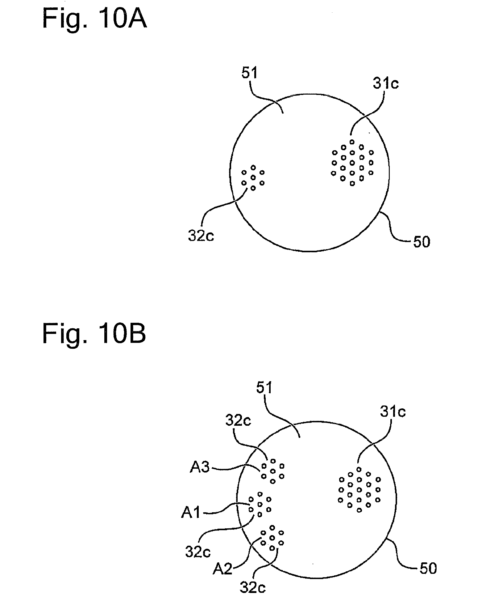
[0024] FIG. 10A illustrates an example of a configuration of fluid ejection ports of the static pressure plate.
[0025] FIG. 10B illustrates an example of a configuration of fluid ejection ports of the static pressure plate.
[0026] FIG. 11 illustrates an example of a substrate holding mechanism of the polishing unit.
[0027] FIG. 12 illustrates an example of the substrate holding mechanism of the polishing unit.
[0028] FIG. 13 illustrates another example of the polishing unit.
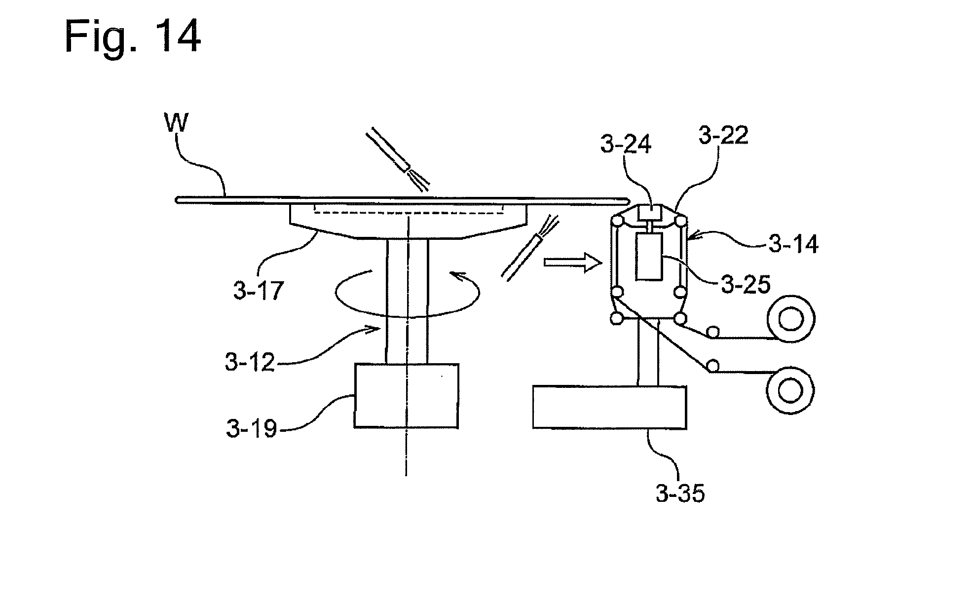
[0029] FIG. 14 illustrates another example of the polishing unit.
DESCRIPTION OF EMBODIMENTS
First Embodiment
[0030] FIG. 1 is a plan view of a substrate processing system including a substrate processing apparatus according to one embodiment. The substrate processing system 1 includes: a load/unload section 2 including front load units 3; a first polishing unit 8 and a second polishing unit 9 each as a substrate processing apparatus; a cleaning unit 11, a drying unit 13; and a controlling device 14. In the load/unload section 2, a first transport robot 4 is installed. The first transport robot 4 is movable along an arrangement direction of the front load units 3. Further, a second transport robot 6, a first wafer station 5 and a second wafer station 7 are installed adjacent to the first polishing unit 8 and the second polishing unit 9. Also, a third transport robot 10 is installed adjacent to the cleaning unit 11, and a fourth transport robot 12 is installed between the cleaning unit 11 and the drying unit 13.
[0031] Each front load unit 3 is configured to be able to mount one or more wafer cassettes each storing plural wafers. Examples of the wafer cassette include an open cassette, a standard manufacturing interface (SMIF) pod and a front opening unified pod (FOUP). The first transport robot 4 takes a wafer out of the wafer cassette mounted on the front load unit 3 and places the wafer on the wafer station 5.
[0032] The wafer station 5 includes a wafer inverter (not shown in the figure) that inverts the wafer placed by the first transport robot 4 upside-down. The second transport robot 6 takes the inverted wafer (in a face-down state) out of the wafer station 5 and transports the wafer to the polishing unit 8 or the polishing unit 9. As will be described later, each of the polishing unit 8 and the polishing unit 9 includes a substrate holding mechanism and a polishing head. The substrate holding mechanism holds and rotates the wafer. The polishing head includes a polishing tool. Each of the polishing unit 8 and the polishing unit 9 is a so-called back surface polishing apparatus, which rotates the wafer by the substrate holding mechanism and polishes the back surface (facing upward) of the water with the polishing tool of the polishing head. Here, explanation will be given of the case where both of the polishing unit 8 and the polishing unit 9 are back surface polishing apparatuses. The wafer taken out of the wafer cassette undergoes a back surface polishing process by either of the two polishing units. Thereafter, the wafer is cleaned, dried and returned to the wafer cassette. In another embodiment, one of the polishing units may be a back surface polishing apparatus and the other of the polishing units may be a bevel polishing apparatus or an apparatus for polishing an outer peripheral area of the wafer. In this case, the wafer undergoes a polishing process by one of the polishing units first and then by the other of the polishing units, and is then cleaned and dried.
[0033] The second transport robot 6 places the wafer having undergone the process by the polishing unit 8 or the polishing unit 9 on the wafer station 7. The third transport robot 10 takes the polished wafer out of the wafer station 7 and transports the wafer to the cleaning unit 11. The cleaning unit 11 performs a cleaning process on the polished wafer. In one embodiment, the cleaning unit 11 includes an upper roll sponge and a lower roll sponge arranged so as to sandwich the wafer in-between and cleans both surfaces of the wafer with these sponges while supplying a cleaning liquid to both surfaces of the wafer.
[0034] The fourth transport robot 12 takes out the wafer cleaned by the cleaning unit 11 and transports the wafer to the drying unit 13. The drying unit 13 dries the cleaned wafer. In one embodiment, the drying unit 13 spin-dries the wafer by rotating the wafer around an axis of the wafer at a high speed. Then, the dried wafer is taken out by the first transport robot 4 and returned to the wafer cassette.
[0035] The controlling device 14 controls operations of each unit of the above-described substrate processing system 1. The controlling device 14 includes a memory storing various setting data and various programs and a CPU executing the programs stored in the memory. A storage medium as the memory may include a volatile storage medium and/or a non-volatile storage medium. The storage medium may include one or more of any storage media such as a ROM, a RAM, a hard disk, a CD-ROM, a DVD-ROM and a flexible disk. The programs stored in the memory may include a program for controlling the transportation by each transport robot, a program for controlling the polishing process by each polishing unit, a program for controlling the cleaning process by the cleaning unit and a program for controlling the drying process by the drying unit. Also, the controlling device 14 is configured to be able to communicate with a host controller (not shown in the figure) that totally controls the substrate processing system 1 and other related apparatuses and to be able to exchange data with a database held by the host controller.
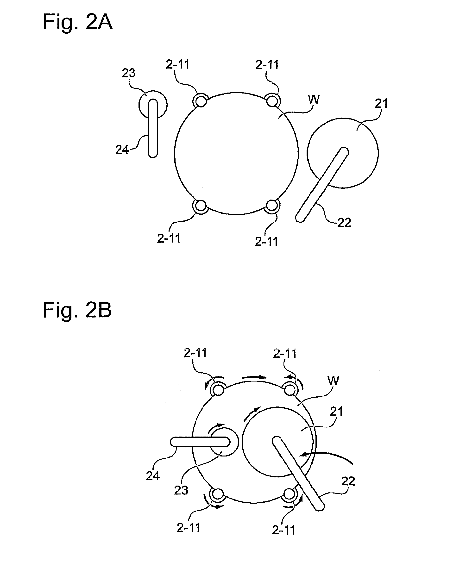
[0036] FIGS. 2A and 2B are schematic plan views each illustrating a configuration of the polishing head of the polishing unit. FIG. 2A shows the polishing head at a retracted position. FIG. 2B shows the polishing head at a polishing position. The polishing unit of the present embodiment includes plural polishing heads. Hereinafter, an explanation will be given of the case where the polishing unit includes two polishing heads 21, 23, though the polishing unit may include three or more polishing heads. Each polishing unit is provided with a rinse liquid supply nozzle (see FIG. 12) for supplying a rinse liquid to a wafer W, though the rinse liquid supply nozzle is omitted in FIGS. 2A and 2B.
[0037] The polishing head 21 has a larger diameter than a radius of the wafer W. One or more polishing tapes each as a polishing tool is attached to a bottom surface (a side contacting the wafer) of the polishing head 21. For example, three polishing tapes are radially arranged on the bottom surface of the polishing head 21. Both ends of the polishing tape is held by two reels (not shown in the figure) disposed in the polishing head 21, and a lower surface of the polishing tape stretching between the two reels can contact the wafer surface. Note that the polishing tool may be any other polishing tool such as a pad containing abrasive grains and fixed abrasive grains. The polishing head 21 is rotatably held by one end of a swing arm 22. The polishing head 21 is rotated by a head rotation mechanism (not shown in the figure) provided at the one end of the swing arm 22. The other end of the swing arm 22 is connected to a swing shaft (not shown in the figure). The swing shaft is rotated by rotation of a shaft rotation mechanism (not shown in the figure), whereby the swing arm 22 is caused to swing (for example, from the state shown in FIG. 2A to the state shown in FIG. 2B, and vice versa). Swinging of the swing arm 22 causes the polishing head 21 to swing between the retracted position (FIG. 2A) and the polishing position (FIG. 2B). Also, the swing shaft is coupled with a lift mechanism (not shown in the figure), by which the polishing head 21 is lifted up and down.
[0038] The polishing head 23 has a smaller diameter than the diameter of the polishing head 21. One or more polishing tapes each as a polishing tool is attached to a bottom surface (a side contact the wafer) of the polishing head 23. For example, three polishing tapes are radially arranged on the bottom surface of the polishing head 23. Both ends of the polishing tape is held by two reels (not shown in the figure) disposed in the polishing head 23, and a lower surface of the polishing tape stretching between the two reels can contact the wafer surface. Note that the polishing tool may be any other polishing tool such as a pad containing abrasive grains and fixed abrasive grains. The polishing head 23 is rotatably held by one end of a swing arm 24. The polishing head 23 is rotated by a head rotation mechanism (not shown in the figure) provided at the one end of the swing arm 24. The other end of the swing arm 24 is connected to a swing shaft (not shown in the figure). The swing shaft is rotated by rotation of a shaft rotation mechanism (not shown in the figure), whereby the swing arm 24 is caused to swing. Swinging of the swing arm 24 causes the polishing head 23 to swing between the retracted position (FIG. 2A) and the polishing position (FIG. 2B) (for example, from the state shown in FIG. 2A to the state shown in FIG. 2B, and vice versa). Also, the swing shaft is coupled with a lift mechanism (not shown in the figure), by which the polishing head 23 is lifted up and down. The wafer W is held and rotated by the substrate holding mechanism. The substrate holding mechanism includes, for example, plural rollers 2-11 (FIGS. 2A, 2B and 12) arranged at the outer periphery of the wafer W. With the wafer W being held between these rollers 2-11, each roller 2-11 rotates about its axis, and this causes the wafer W to rotate without revolution of each roller 2-11. Alternatively, as shown in FIG. 11, the substrate holding mechanism may include chucks 1-11 that revolve while holding the wafer W and thereby cause the wafer W to rotate. As shown in FIG. 2B, a rotation direction of each polishing head 21, 23 may be either the same as or different from a rotation direction of the wafer W. Also, the polishing heads 21, 23 may rotate in different directions.
[0039] Further, a polishing surface (the back surface in the present embodiment) of the wafer W is supplied with a polishing liquid or pure water by a nozzle (not shown in the figure).
[0040] One reason for using the polishing head 23 with a relatively smaller diameter in addition to the polishing head 21 with a relatively larger diameter is as follows. The polishing head 21 contacts the outer periphery of the wafer W for a short period of time, which leads to a relatively lower polishing rate of the outer periphery. For this reason, the polishing head 23 with the smaller diameter supplementarily polishes the outer periphery of the wafer W. This additional polishing of the outer periphery of the wafer W by the polishing head 23, which may be made either at the same time as or after the polishing by the polishing head 21, makes the polishing amount of the back surface of the wafer W more uniform. This can improve the in-plane uniformity of the back surface of the wafer W after the polishing process.
[0041] FIG. 3 is a schematic side view of the polishing unit according to the first embodiment. The substrate holding mechanism is omitted in the figure. In the polishing units 8, 9, the above-described polishing heads 21, 23 contact the back surface of the wafer W to polish a back surface S1 of the wafer. At this time, the polishing heads 21, 23 press the wafer W from the back surface S1 toward a front surface S2 (in this example, from an upper side toward a lower side), and accordingly a substrate support mechanism (static pressure support mechanism) 30 supports the wafer W from the front surface S2 side, which is opposite to the polishing heads. In other words, the static pressure support mechanism 30 applies a supporting force from the front surface of the wafer W to resist the pressing force of the polishing heads 21, 23 on the back surface of the wafer W, and this prevents the wafer W from bending.
[0042] The static pressure support mechanism 30 includes a static pressure plate 31 and a static pressure plate 33. The static pressure plate 31 is provided corresponding to the polishing head 21. The static pressure plate 31 is slightly larger than the diameter of the polishing head 21, and configured and disposed so as to be able to cover the entire polishing head 21 in a plan view. The static pressure plate 31 includes a support surface 32 on a side facing the wafer W and is disposed with a slight gap between the support surface 32 and the front surface of the wafer W. The static pressure plate 31 includes a fluid supply passage, which will be described later, and a fluid (either liquid or gas, e.g., pure water) is supplied to the support surface 32 via the fluid supply passage. With this fluid, the static pressure plate 31 supports the front surface of the wafer W in a non-contact manner.
[0043] The static pressure plate 33 is provided corresponding to the polishing head 23. The static pressure plate 33 is slightly larger than the diameter of the polishing head 23, and configured and disposed so as to be able to cover the entire polishing head 23 in a plan view. The static pressure plate 33 includes a support surface 34 on a side facing the wafer W and is disposed with a slight gap between the support surface 34 and the front surface of the wafer W. The static pressure plate 33 includes a fluid supply passage, which will be described later, and a fluid (either liquid or gas, e.g., pure water) is supplied to the support surface 34 via the fluid supply passage. With this fluid, the static pressure plate 33 supports the front surface of the wafer W in a non-contact manner.
[0044] FIGS. 4A to 4C illustrate examples of a configuration of the static pressure plate. The substrate holding mechanism is omitted in the figures. Although the explanation is given of the static pressure plate 31, the static pressure plate 33 has the same configuration. However, the static pressure plate 31 and the static pressure plate 33 may have different types of configuration. For example, the static pressure plate 31 may have a configuration shown in FIG. 4A while the static pressure plate 33 may have a configuration shown in FIG. 4B. Alternatively, the static pressure plate 31 and the static pressure plate 33 may have any other configuration than those shown in FIGS. 4A to 4C.
[0045] In the example shown in FIG. 4A, the static pressure plate 31 includes a fluid supply passage 31a for introducing a fluid 41, which is a pressurized fluid (pressure fluid). The fluid supply passage 31a connects to a pocket (recessed portion) 31b for holding the fluid 41. The load applied by the polishing head 21 to the back surface S1 of the substrate W is received by the fluid 41 in the pocket 31b and a fluid overflowed from the pocket 31b onto the support surface 32 of the static pressure plate 31. In the example shown in FIG. 4B, the fluid 41 introduced from the fluid supply passage 31a spreads over the entire support surface 32 and receives the load applied by the polishing head 21 to the back surface of the substrate W. In the example shown in FIG. 4C, multiple holes 31c are formed in the support surface 32 of the static pressure plate 31, and the fluid 41 is supplied to the support surface 32 from the fluid supply passage 31a through these holes 31c. The fluid 41 supplied to the support surface 32 receives the load applied by the polishing head 21 to the back surface S1 of the substrate W. FIGS. 4A to 4C also show the plural rollers 2-11 (FIGS. 2A, 2B and 12) as the substrate holding mechanism described above with reference to FIGS. 2A and 2B. With the wafer W being held between these rollers 2-11, each roller 2-11 rotates about its axis, and this causes the wafer W to rotate without revolution of each roller 2-11. Alternatively, as shown in FIG. 11, the substrate holding mechanism may include the chucks 1-11 that revolve while holding the wafer W and thereby cause the wafer W to rotate.
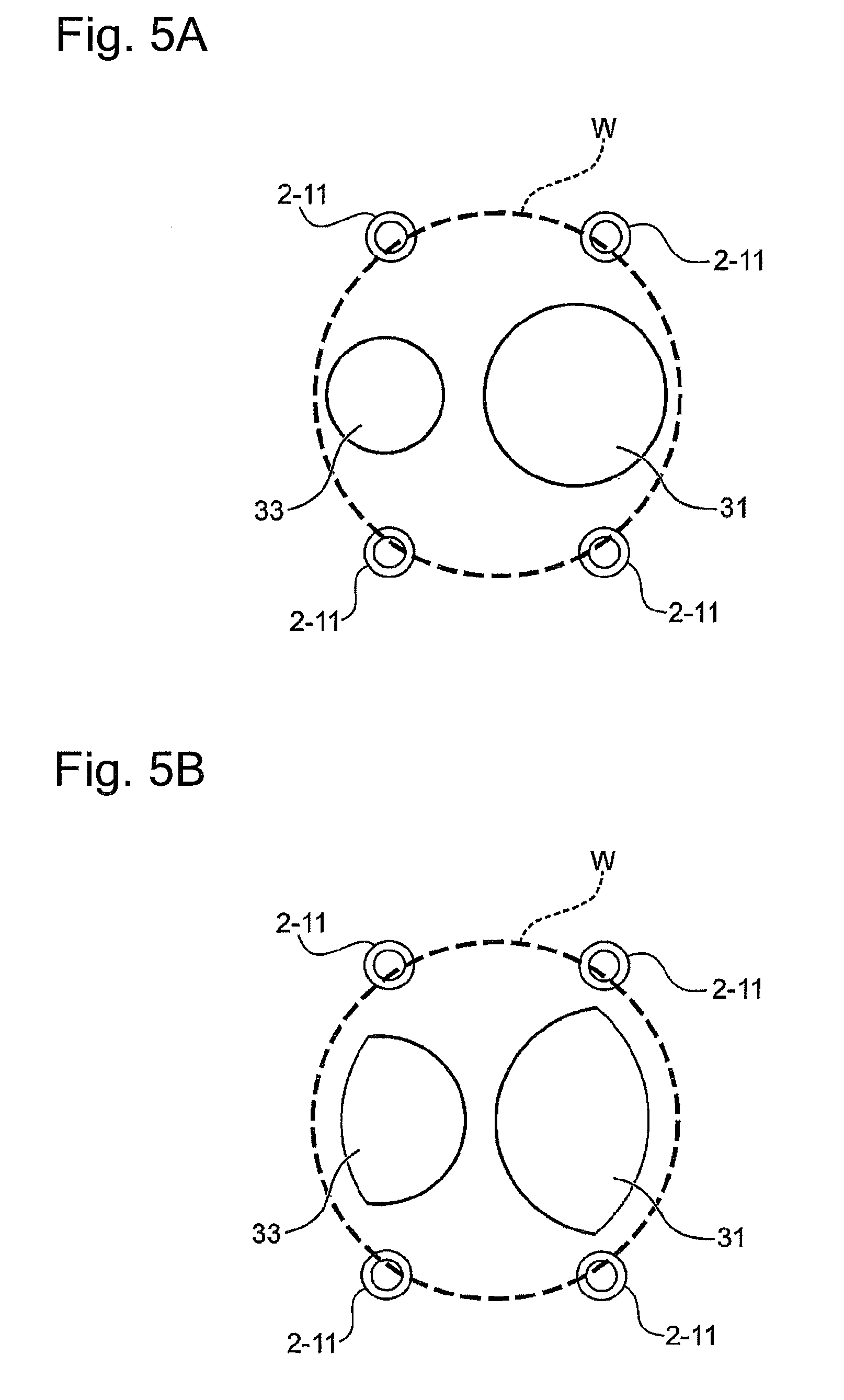
[0046] FIGS. 5A and 5B illustrate examples of a planar shape of the static pressure plate. In the example shown in FIG. 5A, the static pressure plates 31, 33 have circular shapes respectively concentric to the polishing heads 21, 23. Diameters of the static pressure plates 31, 33 are respectively the same as, or slightly larger than, the diameters of the polishing heads 21, 23. In the example shown in FIG. 5B, the diameter of the static pressure plate 31 constitutes a part of a circle or an ellipse that is larger than the diameter of the polishing head 21, and the diameter of the static pressure plate 33 constitutes a part of a circle or an ellipse that is larger than the diameter of the polishing head 23. Also, in FIGS. 5A and 5B, the static pressure plates 31, 33 are shaped such that their portions adjacent to the outer periphery of the wafer W do not interfere with the substrate holding mechanism (e.g., the chucks 1-11 shown in FIG. 11) for holding the wafer W. In the case where the substrate holding mechanism is one that does not rotate together with the wafer W (e.g., the rollers 2-11 shown in FIGS. 5A, 5B and 12), the static pressure plates 31, 33 may overlap the outer periphery of the wafer W or may extend outward beyond the outer periphery.
Second Embodiment
[0047] FIG. 6A is a schematic side view of the polishing unit according to a second embodiment. FIG. 6B is a schematic plan view of the polishing unit according to the second embodiment. The substrate holding mechanism is omitted in the figures. The polishing unit of the present embodiment is different from the polishing unit of the first embodiment in that the polishing head 23 with the smaller diameter swings while performing the polishing process. The other configurations of the second embodiment are the same as those of the first embodiment, and redundant explanations will be omitted.
[0048] As described above, the polishing head 23 is caused to swing by rotation of the swing arm 24 about the swing shaft. Also, the static pressure plate 33 follows the swing of the polishing head 23. That is, along with the movement of the polishing head 23, the static pressure plate 33 moves so as to always cover the polishing head 23 in a plan view.
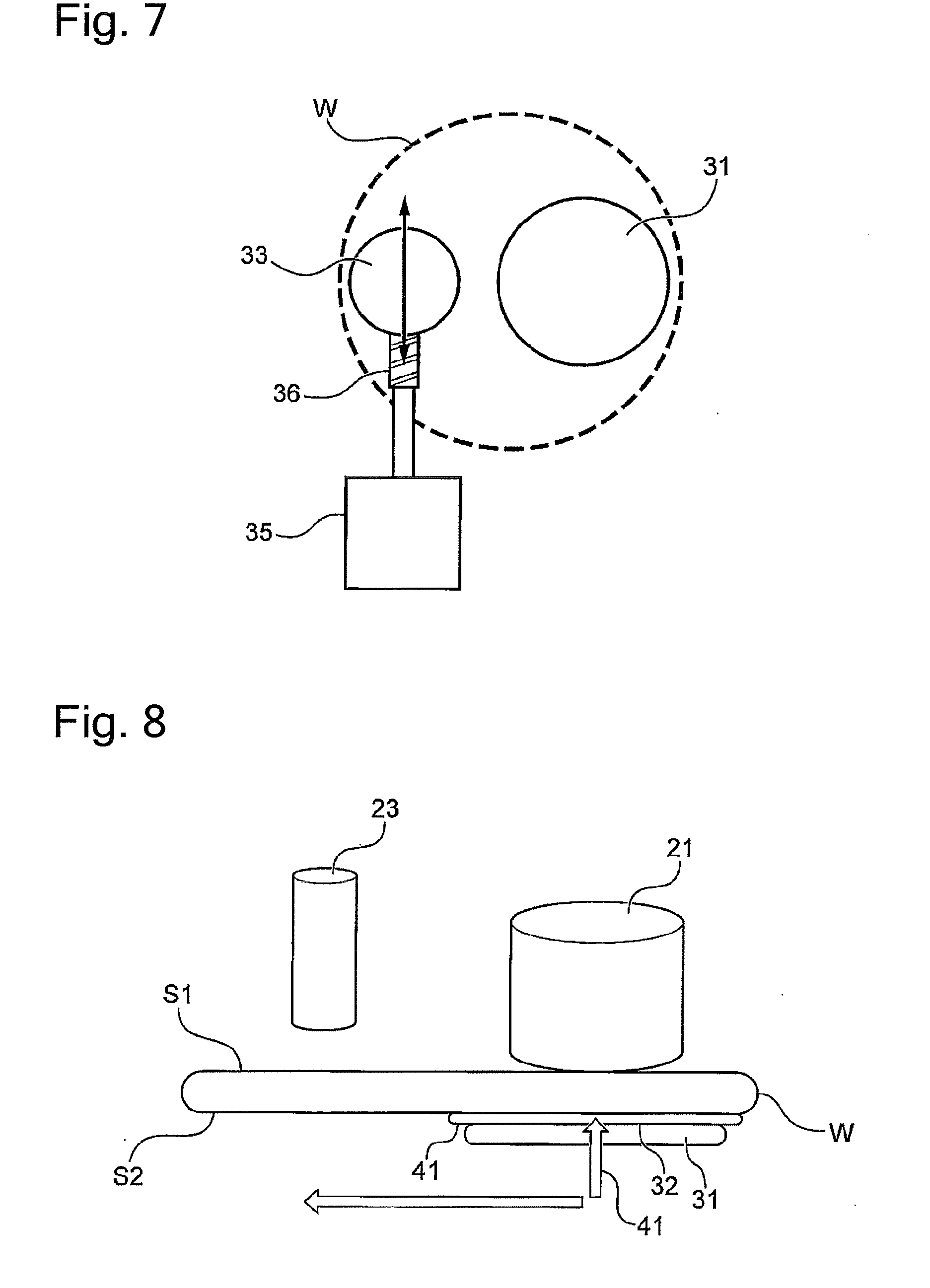
[0049] FIG. 7 illustrates an example of a configuration of a moving mechanism of the static pressure plate. The substrate holding mechanism is omitted in the figure. In this example, the static pressure plate 33 is coupled with a ball screw mechanism 36, which is driven by a motor 35. The ball screw mechanism 36 converts rotary motion of the motor 35 into linear motion, by which the static pressure plate 33 is reciprocated. The moving mechanism of the static pressure plate is not limited to the motor and the ball screw mechanism, and any other driving mechanism including a rack-and-pinion mechanism, an air cylinder and a solenoid may be used. While the polishing head 23 swings in an arc, the static pressure plate 33 linearly moves. For this reason, the static pressure plate 33 preferably has a larger diameter than the diameter of the polishing head 23 so that the static pressure plate 33 can always cover the area of the polishing head 23.
Third Embodiment
[0050] FIG. 8 is a schematic side view of the polishing unit according to a third embodiment. The substrate holding mechanism is omitted in the figure. The polishing unit of the present embodiment is different from the polishing unit of the first embodiment in that the static pressure plate 33 with the smaller diameter is not provided and the static pressure plate 31 with the larger diameter is movable. The other configurations of the third embodiment are the same as those of the first embodiment, and redundant explanations will be omitted.
[0051] In the present embodiment, the static pressure plate 31 is movable between a position corresponding to the polishing head 21 and a position corresponding to the polishing head 23. As described above, when at the position corresponding to the polishing head 21, the static pressure plate 31 covers the polishing head 21 in a plan view. Further, when at the position corresponding to the polishing head 23, the static pressure plate 31 covers the polishing head 23 in a plan view. From the size relationship between the polishing head 21 and the polishing head 23, the static pressure plate 31, which corresponds to the polishing head 21 with the larger diameter, is sufficiently larger than the polishing head 23. The moving mechanism of the polishing head 23 may be the same as that explained in the second embodiment for reciprocating the static pressure plate 33. That is, the moving mechanism may be any driving mechanism such as a motor and a ball screw mechanism, a rack-and-pinion mechanism, an air cylinder and a solenoid. In the present embodiment, polishing by the polishing head 23 is made after polishing by the polishing head 21 is finished. Alternatively, this order of polishing may be inverted. At the time of polishing by the polishing head 21, the static pressure plate 31 is situated at the position corresponding to (facing) the polishing head 21. The polishing head 21 performs polishing while the load from the polishing head 21 is received by the static pressure plate 31. Then, at the time of polishing by the polishing head 23, the static pressure plate 31 is moved by the moving mechanism to the position corresponding to (facing) the polishing head 23. The polishing head 23 performs polishing while the load from the polishing head 23 is received by the static pressure plate 31.
Fourth Embodiment
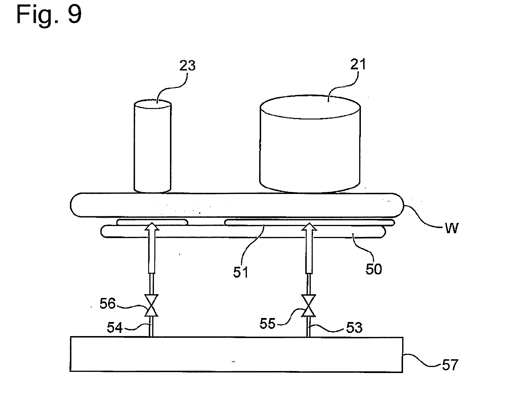
[0052] FIG. 9 is a schematic side view of the polishing unit according to a fourth embodiment. FIGS. 10A and 10B are plan views of the static pressure plate. The substrate holding mechanism is omitted in the figures. The present embodiment is different from the first embodiment in that a common static pressure plate 50 is provided for the two polishing heads. The other configurations of the fourth embodiment are the same as those of the first embodiment, and redundant explanations will be omitted.
[0053] The static pressure plate 50 is connected to two fluid supply lines 53, 54, which are respectively provided with flow rate control valves 55, 56. The flow rate is controlled by the flow rate control valves 55, 56 based on signals from the controlling device 14. Further, the fluid supply lines 53, 54 are connected to a fluid supply source 57 and supplied with a pressure fluid (either liquid or gas) by the fluid supply source 57. The liquid is, for example, DIW (pure water).
[0054] As shown in FIG. 10A, a support surface 51 of the static pressure plate 50 includes plural holes or the fluid ejection ports 31c at an area corresponding to the polishing head 21 and includes plural holes or the fluid ejection ports 32c at an area corresponding to the polishing head 23 (see FIG. 4C). The plural fluid ejection ports 31c communicate with the fluid supply line 53. The plural fluid ejection ports 32c communicate with the fluid supply line 54. The fluid supplied from the fluid supply line 53 to the support surface 51 via the fluid ejection ports 31c receives the load from the polishing head 21, and the fluid supplied from the fluid supply line 54 to the support surface 51 via the fluid ejection ports 32c receives the load from the polishing head 23. When only one of the two polishing heads 21, 23 is used, supply of the fluid to the static pressure plate corresponding to the unused polishing head may be shut off by the flow rate control valve 55 or 56. Note that on-off valves may be used instead of the flow rate control valves 55, 56.
[0055] In the case where the polishing head 23 with the smaller diameter is configured to swing, the fluid ejection ports 32c may be formed in plural areas A1, A2 and A3 as shown in FIG. 10B, and the fluid ejection ports in these areas may be respectively connected to individual fluid supply lines 54A1, 54A2 and 54A3 (not shown in the figure). Control valves provided for the respective fluid supply lines may be controlled so as to successively supply the fluid to the fluid ejection ports 32c at the areas A1, A2 and A3. Alternatively, the fluid may be supplied to the fluid ejection ports 32c at the areas A1, A2 and A3 (movable range of the polishing head 23) all at once, such that the supplied fluid covers the entire swinging range of the polishing head 23.
[0056] FIG. 11 illustrates an example of the substrate holding mechanism of the polishing unit. To simplify the illustration, the figure shows one polishing head and one static pressure plate, though in reality, plural polishing heads and plural static pressure plates are disposed as described above. Each polishing head and each static pressure plate are shaped to avoid each chuck 1-11 at the polishing position on the outer periphery side of the wafer. In this example, plural chucks 1-11 arranged at the outer periphery of the wafer W clamp the outer periphery of the wafer W, whereby the wafer W is held. Each chuck 1-11 is fixed on a rotary base 1-16 of a cylindrical substrate rotation mechanism 1-10. The rotary base 1-16 is rotatably supported by a stationary member 1-14 via angular contact ball bearings 20, 20. A rotor of a hollow motor 1-12 is fixed to the rotary base 1-16, and a stator is fixed to the stationary member 1-14. In response to rotation of the hollow motor 1-12, the rotary base 1-16 rotates relative to the stationary member 1-14, and each chuck revolves while holding the wafer W. At this time, each chuck 1-11 revolves around the center of the wafer W. Each chuck 1-11 is lifted by a lift mechanism 1-30 to release the wafer W. In FIG. 11, a polishing head 1-50 includes a polishing tape 1-61 as a polishing tool. The polishing head 1-50 is coupled with one end of a swing arm 1-53 via a shaft 1-51, and the other end of the swing arm 1-53 is fixed to a swing shaft 1-54. The swing shaft 1-54 is coupled with a shaft rotation mechanism 1-55. The swing shaft 1-54, when driven by the shaft rotation mechanism 1-55, causes the polishing head 1-50 to move between the retracted position (FIG. 2A) and the polishing position (FIG. 2B). The swing shaft 1-54 is further coupled with a lift mechanism 1-56 that vertically moves the polishing head 1-50. The lift mechanism 1-56 lifts the polishing head 1-50 up and down via the swing shaft 1-54 and the shaft 1-51. The polishing head 1-50 is lifted down by the lift mechanism 1-56 until the polishing head 1-50 contacts the upper surface of the wafer W. Examples of the lift mechanism 1-56 include an air cylinder and a combination of a servomotor and a ball screw. A static pressure support mechanism 1-90 includes a static pressure plate 1-91 configured as described above. The static pressure plate 1-91 is lifted up and down by a lift mechanism 1-98 and rotated by a rotation mechanism 1-99. Note that, in the case of using the substrate holding mechanism with this configuration, the polishing head and the static pressure plate need to be shaped and disposed so as not to interfere with the chucks 1-11, which revolve during the polishing process.
[0057] FIG. 12 illustrates an example of the substrate holding mechanism of the polishing unit. In this example, plural rollers 2-11 arranged at the outer periphery of the wafer W hold the wafer W in between. In this state, each roller 2-11 rotates about its axis, and this causes the wafer W to rotate without revolution of each roller 2-11. In the figure, reference numeral 2-1 denotes the back surface of the wafer W and reference numeral 2-2 denotes the front surface of the wafer W. A substrate holding mechanism 2-10 includes the plural rollers 2-11 that can contact the outer periphery of the wafer W, and a roller rotation mechanism 2-12 that causes the rollers 2-11 to rotate about their respective axes. In one example, four rollers are provided, though more than or less than four rollers may be provided. In one embodiment, the roller rotation mechanism 2-12 includes a motor, a belt, a pulley, etc. The roller rotation mechanism 2-12 causes the plural rollers 2-11 to rotate in the same direction at the same speed. During polishing of the wafer W, the outer periphery of the wafer W is held between the plural rollers 2-11. The wafer W is held horizontally and caused to rotate about its axis by rotation of the rollers 2-11. A polishing head assembly 2-49 includes a polishing head 2-50, which is coupled with the above-described swing arm (omitted in the figure). The polishing head 2-50 is coupled with a head shaft 2-51 attached to the swing arm. The head shaft 2-51 is coupled with a head rotation mechanism 2-58 that causes the polishing head 2-50 to rotate about the axis of the polishing head 2-50. Further, the head shaft 2-51 is coupled with an air cylinder 2-57 as a load application device that applies a downward load to the polishing head 2-50. The polishing head 2-50 includes plural polishing tapes 2-61 each as a polishing tool for polishing the surface of the wafer W. In one embodiment, the head rotation mechanism 2-58 includes a motor, a belt, a pulley, etc. A static pressure plate 2-90 includes plural fluid ejection ports 2-94 formed in a support surface 2-91, and a fluid supply passage 2-92 connected to the fluid ejection ports 2-94. The fluid supply passage 2-92 is connected to a fluid supply source (not shown in the figure). Also, a rinse liquid supply nozzle 2-27 is provided that supplies a rinse liquid to the center of the wafer W, and the rinse liquid spreads over the wafer surface by the centrifugal force of the rotating wafer W. Although FIG. 12 shows one polishing head, two (or more) polishing heads are provided as described above.
[0058] In the case of using the substrate holding mechanism of this configuration, the polishing head and the static pressure plate are set to be shaped and placed so as to avoid the plural rollers 2-11, which are at fixed positions. This keeps the polishing head and the static pressure plate from interfering with the chucks (rollers) during rotation of the wafer W. Accordingly, the polishing head and the static pressure plate can be placed so as to reach the outer periphery of the wafer W or to extend radially outward beyond the outer periphery of the wafer W.
[0059] FIGS. 13 and 14 illustrate another example of the polishing unit. In this example, the front surface of the wafer W faces upward, and the back surface of the wafer W faces downward. In this state, a polishing head 3-14 including a polishing tape 3-22 polishes the outer periphery of the back surface of the wafer W while being moved by a polishing head moving mechanism 3-35, and in this way, the polishing head 3-14 polishes the entire area of the outer periphery including a bevel part of the wafer (FIG. 14). In this example, a substrate holding mechanism 3-12 is composed of a substrate stage 3-17 holding the wafer W by vacuum suction, and a motor 3-19 rotating the substrate stage 3-17. The polishing head 3-14 includes plural rollers holding the polishing tape 3-22 as a polishing tool, a pressing member 3-24 pressing the polishing tape 3-22 against the back surface of the wafer W, and an air cylinder 3-25 as an actuator to apply a pressing force to the pressing member 3-24. The polishing tape 3-22 is fed, at a constant speed, from a supply reel to a take-up reel via the polishing head 3-14. The polishing head 3-14 is coupled with a polishing head moving mechanism 3-35. The polishing head moving mechanism 3-35 is configured to move the polishing head 3-14 to the outside of the wafer W in a radial direction. The polishing head moving mechanism 3-35 is composed of, for example, a combination of a ball screw and a servomotor. Liquid supply nozzles for supplying a polishing liquid (pure water) to the wafer W are provided above and below the wafer W held by the substrate stage 3-17. In this configuration, the above-described static pressure plate 31 or 33 is disposed at the outer periphery (the position corresponding to the polishing head 3-14 in FIG. 13) of the front surface of the wafer W, and this can prevent the wafer W from bending. In this example, the static pressure plate 31 or 33 is disposed above the wafer W. The positions of the polishing head 3-14 and the static pressure plate 31 or 33 may be interchanged. That is, the polishing head 3-14 may be disposed above the wafer W, and the static pressure plate 31 or 33 may be disposed below the wafer W.
[0060] From the above embodiments, at least the following technical ideas can be grasped.
[0061] According to a first aspect, a substrate processing apparatus is provided that includes: a first polishing head configured to polish a first surface of a substrate by sliding a first polishing tool on the first surface; a second polishing head configured to polish the first surface of the substrate by sliding a second polishing tool on the first surface, the second polishing head having a smaller diameter than a diameter of the first polishing head; and a substrate support mechanism configured to support the substrate by a fluid pressure at positions corresponding to the first polishing head and the second polishing head from a second surface of the substrate opposite to the first surface.
[0062] According to the first aspect, the first polishing head polishes the entire first surface of the substrate, and the second polishing head, which has a smaller diameter than the first polishing head, supplementarily polishes the portions with a lower polishing rate on the first surface of the substrate. This allows the substrate to be uniformly polished. Further, the substrate is supported from the second surface of the substrate at positions corresponding to the first polishing head and the second polishing head. This allows the substrate to be supported from the opposite side of the substrate in an appropriate range according to a pressing force by the first polishing head and the second polishing head. Accordingly, this can prevent an unnecessary supporting force from being applied to the substrate at areas other than those corresponding to the first and the second polishing heads. This can further reduce the amount of fluid used.
[0063] According to a second aspect, in the substrate processing apparatus of the first aspect, the substrate support mechanism includes: a first static pressure plate configured to support the substrate at the position corresponding to the first polishing head; and a second static pressure plate configured to support the substrate at the position corresponding to the second polishing head.
[0064] According to the second aspect, the first and the second static pressure plates are provided respectively corresponding to the first and the second polishing heads. This allows the substrate to be supported, with a simple configuration, from the opposite side of the substrate in an appropriate range according to the pressing force by the first polishing head and the second polishing head.
[0065] According to a third aspect, in the substrate processing apparatus of the second aspect, the second polishing head is configured to polish the substrate while swinging during a polishing process, and the second static pressure plate is configured to be able to move so as to follow the second polishing head. For example, the substrate processing apparatus may further comprise: a second arm configured to move the second polishing head; a movable mechanism provided in the substrate support mechanism and configured to move the second static pressure plate; and a controller configured to control the second arm and the movable mechanism such that the second static pressure plate follows the second polishing head.
[0066] According to the third aspect, swinging of the second polishing head with the smaller diameter allows to further improve a polishing rate of the portions on the substrate with a lower polishing rate. As a result, this can shorten the polishing time. Further, the second static pressure plate is configured to move so as to follow the second polishing head, and this allows the second static pressure plate to appropriately support the substrate at the area where the second polishing head is pressed against the substrate.
[0067] According to a fourth aspect, in the substrate processing apparatus of the first aspect, the substrate support mechanism includes a static pressure plate configured to be movable between an area corresponding to the first polishing head and an area corresponding to the second polishing head. For example, the substrate support mechanism may include: a static pressure plate; and a movable mechanism configured to move the static pressure plate between an area corresponding to the first polishing head and an area corresponding to the second polishing head.
[0068] According to the fourth aspect, use of one common static pressure plate enables to support the substrate at the position corresponding to the first polishing head and at the position corresponding to the second polishing head.
[0069] According to a fifth aspect, in the substrate processing apparatus of the first aspect, the substrate support mechanism includes: a static pressure plate configured to support the substrate at the positions corresponding to the first polishing head and the second polishing head; a first fluid line configured to supply a fluid to an area on the static pressure plate corresponding to the first polishing head; and a second fluid line configured to supply a fluid to an area on the static pressure plate corresponding to the second polishing head.
[0070] According to the fifth aspect, the fluid is supplied from the first and the second lines to the areas respectively corresponding to the first and the second polishing heads. This allows the substrate to be supported at the position corresponding to the first polishing head and at the position corresponding to the second polishing head in an appropriate range, without moving the common static pressure plate.
[0071] According to a sixth aspect, in the substrate processing apparatus of the fifth aspect, the second polishing head is configured to polish the substrate while swinging during a polishing process, and the static pressure plate is configured to allow a position at which the fluid is supplied onto the second surface of the substrate to be changed so as to follow the second polishing head. For example, the substrate processing apparatus may further comprise: a second arm configured to move the second polishing head; a plurality of the second fluid line provided in the substrate support mechanism and connected with a plurality of positions on the static pressure plate within a range in which the second polishing head is moved; and a controller configured to control an amount of the fluid to be supplied through each second fluid line, thereby to change positions on the static pressure plate to which the fluid is supplied follows the second polishing head.
[0072] According to the sixth aspect, swinging of the second polishing head with the smaller diameter allows a polishing rate of the portions on the substrate with a lower polishing rate to further improve. As a result, this can shorten the polishing time. Further, the position onto which the fluid is supplied moves so as to follow the second polishing head. This allows the fluid to appropriately support the substrate at the area where the second polishing head is pressed against the substrate.
[0073] According to a seventh aspect, in the substrate processing apparatus of any one of the first to the sixth aspects, the second polishing head is arranged to polish the substrate at a position outside of the first polishing head in a radial direction of the substrate.
[0074] According to the seventh aspect, the outer periphery of the substrate, which tends to have a lower polishing rate, is supplementarily polished. This can improve the in-plane uniformity of the substrate after polishing.
[0075] According to an eighth aspect, in the substrate processing apparatus of any one of the first to the seventh aspects, the substrate processing apparatus includes a back surface polishing apparatus, the first surface of the substrate is a surface on which no device is formed, and the polishing process is performed after a resist is applied to the second surface of the substrate and before an exposure process is performed.
[0076] According to the eighth aspect, the in-plane uniformity of the non-device surface is prevented from affecting an exposure process on the device surface, which is performed later.
[0077] According to a ninth aspect, a substrate processing apparatus is provided that includes: a substrate holding mechanism configured to hold and rotate a substrate, the substrate holding mechanism including plural rollers configured to be able to contact a periphery of the substrate, each roller being configured to be rotatable about an axis thereof; a first polishing head configured to polish a first surface of the substrate by sliding a first polishing tool on the first surface; and a second polishing head configured to polish the first surface of the substrate by sliding a second polishing tool on the first surface, the second polishing head having a smaller diameter than a diameter of the first polishing head.
[0078] According to the ninth aspect, the rollers holding the substrate do not rotate with the substrate. This allows the polishing head to be disposed at the edge portion of the substrate or radially outside of the substrate, which in turn allows the edge portion of the substrate to be polished. Further, the first polishing head polishes the entire substrate, and the second polishing head, which has a smaller diameter than the first polishing head, supplementarily polishes the portions of the substrate with a lower polishing rate. This allows the substrate to be uniformly polished.
[0079] According to a tenth aspect, a substrate polishing method is provided that includes: polishing a first surface of a substrate by sliding a first polishing tool of a first polishing head on the first surface of the substrate and by sliding a second polishing tool of a second polishing head on the first surface of the substrate, the second polishing head having a smaller diameter than a diameter of the first polishing head; and supporting the substrate from a second surface of the substrate at positions corresponding to the first polishing head and the second polishing head, the second surface being opposite to the first surface.
[0080] The tenth aspect produces the same functions and effects as the first aspect.
[0081] According to an eleventh aspect, the substrate processing apparatus method according to tenth aspect, wherein the first surface of the substrate is a surface on which no device is formed, and the polishing process is performed after a resist is applied to the second surface of the substrate and before an exposure process is performed.
[0082] According to a twelfth aspect, a substrate polishing method is provided that includes: rotating a substrate by bringing plural rollers into contact with a periphery of the substrate and rotating each roller about an axis thereof; and polishing, during rotation of the substrate, a first surface of the substrate with a first polishing head and a second polishing head, the second polishing head having a smaller diameter than a diameter of the first polishing head.
[0083] The twelfth aspect produces the same functions and effects as the ninth aspect.
[0084] According to an thirteenth aspect, the substrate processing apparatus method according to twelfth aspect, wherein the first surface of the substrate is a surface on which no device is formed, and the polishing process is performed after a resist is applied to the second surface of the substrate and before an exposure process is performed.
[0085] According to a fourteenth aspect, a non-volatile storage medium storing a program causing a computer to perform a method for controlling a substrate processing apparatus is provided, and the method includes: polishing a first surface of a substrate by sliding a first polishing tool of a first polishing head on the first surface of the substrate and by sliding a second polishing tool of a second polishing head on the first surface of the substrate, the second polishing head having a smaller diameter than a diameter of the first polishing head; and supporting, during the polishing, the substrate from a second surface of the substrate at positions corresponding to the first polishing head and the second polishing head, the second surface being opposite to the first surface.
[0086] The twelfth aspect produces the same functions and effects as the first aspect.
[0087] According to a fifteenth aspect, a non-volatile storage medium storing a program causing a computer to perform a method for controlling a substrate processing apparatus is provided, and the method includes: rotating a substrate by bringing plural rollers into contact with a periphery of the substrate and rotating each roller about an axis thereof; and polishing, during rotation of the substrate, a first surface of the substrate with a first polishing head and a second polishing head, the second polishing head having a smaller diameter than a diameter of the first polishing head.
[0088] The thirteenth aspect produces the same functions and effects as the ninth aspect.
[0089] The embodiments of the present invention has been explained based on several examples. However, the above embodiments have been given to provide understanding of the present invention and is not intended to restrict the present invention to the embodiments. It will be readily understood that any modifications or improvements may be made to the present invention without departing from the scope of the present invention and that the present invention may include its equivalents. Also, elements disclosed in the claims and the specification may be freely combined or omitted as long as at least some of the above-described problems may be solved or at least some of the above-described advantageous effects may be produced.
[0090] The present application claims priority to Japanese Patent Application No. 2017-244060 filed on Dec. 20, 2017. The entire disclosure of Japanese Patent Application No. 2017-244060 filed on Dec. 20, 2017 including specification, claims, drawings and summary is incorporated herein by reference in its entirety.
[0091] The entire disclosure of Japanese Patent Publication No. 2013-172019 (Patent Literature 1), including specification, claims, drawings and summary is incorporated herein by reference in its entirety.
REFERENCE SIGNS LIST
[0092] 1 Substrate processing system [0093] 2 Load/unload section [0094] 3 Front load unit [0095] 4 Transport robot [0096] 5 Wafer station [0097] 6 Transport robot [0098] 7 Wafer station [0099] 8 Polishing unit [0100] 9 Polishing unit [0101] 10 Transport robot [0102] 11 Cleaning unit [0103] 12 Transport robot [0104] 13 Drying unit [0105] 14 Controlling device [0106] 21 Polishing head [0107] 22 Swing arm [0108] 23 Polishing head [0109] 24 Swing arm [0110] 31 Static pressure plate [0111] 32 Support surface [0112] 33 Static pressure plate [0113] 34 Support surface [0114] 41 Fluid [0115] 31a Fluid supply passage [0116] 31b Pocket [0117] 31c Fluid ejection port [0118] 32c Fluid ejection port [0119] 35 Motor [0120] 36 Ball screw mechanism [0121] 50 Static pressure plate [0122] 51 Support surface [0123] 53 Fluid supply line [0124] 54 Fluid supply line [0125] 55 Flow rate control valve [0126] 56 Flow rate control valve
* * * * *
D00000
D00001
D00002
D00003
D00004
D00005
D00006
D00007
D00008
D00009
D00010
D00011
D00012
XML
uspto.report is an independent third-party trademark research tool that is not affiliated, endorsed, or sponsored by the United States Patent and Trademark Office (USPTO) or any other governmental organization. The information provided by uspto.report is based on publicly available data at the time of writing and is intended for informational purposes only.
While we strive to provide accurate and up-to-date information, we do not guarantee the accuracy, completeness, reliability, or suitability of the information displayed on this site. The use of this site is at your own risk. Any reliance you place on such information is therefore strictly at your own risk.
All official trademark data, including owner information, should be verified by visiting the official USPTO website at www.uspto.gov. This site is not intended to replace professional legal advice and should not be used as a substitute for consulting with a legal professional who is knowledgeable about trademark law.