Heterogeneously Integrated Power Converter Assembly
Jacobson; Boris S. ; et al.
U.S. patent application number 16/055792 was filed with the patent office on 2019-05-16 for heterogeneously integrated power converter assembly. The applicant listed for this patent is RAYTHEON COMPANY. Invention is credited to Jason Adams, Steven D. Bernstein, Boris S. Jacobson, Steven M. Lardizabal, Jeffrey R. Laroche.
| Application Number | 20190149039 16/055792 |
| Document ID | / |
| Family ID | 63364179 |
| Filed Date | 2019-05-16 |


| United States Patent Application | 20190149039 |
| Kind Code | A1 |
| Jacobson; Boris S. ; et al. | May 16, 2019 |
HETEROGENEOUSLY INTEGRATED POWER CONVERTER ASSEMBLY
Abstract
A power converter assembly is provided and includes high quality factor (Q) shield-to-transistor integrated low-inductance capacitor elements to divert common mode (CM) currents, high Q shield-to-shield integrated low-inductance capacitor elements to compliment line-to-line filter capacitors and high Q baseplate integrated low-inductance capacitor elements to attenuate residual CM currents.
| Inventors: | Jacobson; Boris S.; (Westford, MA) ; Bernstein; Steven D.; (Brighton, MA) ; Lardizabal; Steven M.; (Westford, MA) ; Adams; Jason; (Medway, MA) ; Laroche; Jeffrey R.; (Austin, TX) | ||||||||||
| Applicant: |
|
||||||||||
|---|---|---|---|---|---|---|---|---|---|---|---|
| Family ID: | 63364179 | ||||||||||
| Appl. No.: | 16/055792 | ||||||||||
| Filed: | August 6, 2018 |
Related U.S. Patent Documents
| Application Number | Filing Date | Patent Number | ||
|---|---|---|---|---|
| 62542023 | Aug 7, 2017 | |||
| Current U.S. Class: | 363/13 |
| Current CPC Class: | H02M 1/44 20130101; H01F 2027/2809 20130101; H01F 27/2885 20130101; H05K 2201/086 20130101; H02M 1/4258 20130101; H01F 27/2804 20130101; H05K 1/165 20130101; H01F 2027/2819 20130101; H01F 27/36 20130101 |
| International Class: | H02M 1/44 20060101 H02M001/44; H01F 27/28 20060101 H01F027/28; H01F 27/36 20060101 H01F027/36; H05K 1/16 20060101 H05K001/16; H02M 1/42 20060101 H02M001/42 |
Goverment Interests
FEDERAL SPONSORED RESEARCH AND DEVELOPMENT
[0002] This invention was made with government support under contract number N00014-13-C-0231 awarded by United States Navy. The government has certain rights in the invention.
Claims
1. An integrated converter of an antenna power system, the integrated converter comprising: a baseplate; a transformer area interposed between input and output sections, the transformer area comprising: a magnetic core top portion; a magnetic core bottom portion disposed on the baseplate; a magnetic core pillar extending between central sections of the magnetic core top and bottom portions; and successive layers of shield and magnetic core materials, windings and magnetic core materials and shield and magnetic core materials interleaved between dielectric material layers at opposite sides of the magnetic core pillar.
2. The integrated converter according to claim 1, wherein the integrated converter is provided as a galvanically-isolated bridge converter.
3. The integrated converter according to claim 1, wherein the shield materials comprise metallic materials.
4. The integrated converter according to claim 1, wherein: the magnetic core top and bottom portions have similar widths, the magnetic core pillar has a lesser width than the magnetic core top and bottom portions, and the successive layers of the windings and the magnetic core materials extend outwardly to respective edges of the magnetic core top and bottom portions.
5. The integrated converter according to claim 1, wherein the successive layers comprise: primary winding materials; first and second primary shield materials above and below the primary winding materials; secondary winding materials; and first and second secondary shield materials above and below the secondary winding materials.
6. The integrated converter according to claim 5, wherein: the first and second primary shield materials extend continuously into the transformer area from the input section, and the first and second secondary shield materials extend continuously into the transformer area from the output section.
7. The integrated converter according to claim 5, wherein: the first and second primary shield materials discontinuously correspond to shield materials in the output section, and the first and second secondary shield materials discontinuously correspond to shield materials in the input section.
8. The integrated converter according to claim 1, wherein the magnetic core materials in each successive layer of shield and magnetic core materials form a C-shape or a reverse C-shape about the magnetic core pillar.
9. An antenna power system, comprising: an alternating current (AC)/direct current (DC) converter, which is receptive of AC; a common bus, which is receptive of DC from the AC/DC converter; a plurality of transmission/reception (T/R) channels coupled to the common bus, each T/R channel comprising: a power amplification assembly; and a discrete input capacitor electrically interposed between the common bus and the power amplification assembly, the power amplification assembly comprising a discrete output capacitor electrically interposed between a power amplifier and an integrated DC/DC converter comprising shields extending into a transformer area.
10. The antenna power system according to claim 9, wherein the integrated DC/DC converter is provided as a galvanically-isolated bridge converter.
11. The antenna power system according to claim 9, wherein the transformer area of the integrated DC/DC converter is interposed between an input section comprising the discrete input capacitor and an output section comprising the discrete output capacitor.
12. The antenna power system according to claim 9, wherein the transformer area of the integrated DC/DC converter comprises: a magnetic core top portion; a magnetic core bottom portion disposed on a baseplate; a magnetic core pillar extending between central sections of the magnetic core top and bottom portions; and successive layers of shield and magnetic core materials, windings and magnetic core materials and shield and magnetic core materials interleaved between dielectric material layers at opposite sides of the magnetic core pillar.
13. The antenna power system according to claim 12, wherein the shield materials comprise metallic materials.
14. The antenna power system according to claim 12, wherein: the magnetic core top and bottom portions have similar widths, the magnetic core pillar has a lesser width than the magnetic core top and bottom portions, and the successive layers of the windings and the magnetic core materials extend outwardly to respective edges of the magnetic core top and bottom portions.
15. The antenna power system according to claim 12, wherein the successive layers comprise: primary winding materials; first and second primary shield materials above and below the primary winding materials; secondary winding materials; and first and second secondary shield materials above and below the secondary winding materials.
16. The antenna power system according to claim 15, wherein: the first and second primary shield materials extend continuously into the transformer area from the discrete input capacitor, and the first and second secondary shield materials extend continuously into the transformer area from the discrete output capacitor.
17. The antenna power system according to claim 15, wherein: the first and second primary shield materials discontinuously correspond to shield materials in the discrete output capacitor, and the first and second secondary shield materials discontinuously correspond to shield materials in the discrete input capacitor
18. The antenna power system according to claim 12, wherein the magnetic core materials in each successive layer of shield and magnetic core materials form a C-shape or a reverse C-shape about the magnetic core pillar.
19. A method of forming an integrated direct current (DC)/DC converter, the method comprising: laying down, in an input section, first and second layers of interleaved input section shield materials with layers of dielectric materials interleaved between the first and second layers of interleaved input section shield materials; laying down, in an output section, first and second layers of interleaved output section shield materials with layers of dielectric materials interleaved between the first and second layers of interleaved output section shield materials; assembling, in a transformer area between the input and output sections, a magnetic core pillar between top and bottom magnetic core portions; and interleaving, in the transformer area, layers of dielectric materials with layers of magnetic core materials with windings, extensions of the first layers of input section shield materials or extensions of second layers of output section shield materials.
20. The method according to claim 19, further comprising laying down the magnetic core materials in C- and reverse C-shapes about the magnetic core pillar in the layers of magnetic core materials with windings, extensions of the first layers of input section shield materials or extensions of second layers of output section shield materials.
Description
CROSS-REFERENCE TO RELATED APPLICATIONS
[0001] This application claims the benefit of U.S. Provisional Patent Application No. 62/542,023, filed Aug. 7, 2017, the disclosure of which is incorporated by reference herein in its entirety.
BACKGROUND
[0003] The following description relates to a heterogeneously integrated power converter assembly and, more specifically, to an antenna power system with an integrated direct current (DC)/DC converter.
[0004] In conventional antenna power systems for radar and other similar applications, there are typically massive numbers of off-array subsystems and electro-magnetic interference (EMI) filters that are required to achieve voltage quality. For example, a radar system can include a power distribution unit (PDU), an aperture power room (APR) for power conversion and distribution, multi-cable distribution and an array antenna.
[0005] The PDU can include a 12-phase transformer that is required to provide a voltage step-down and a power factor correction (PFC) that is equal to a lower total harmonic distortion (THD). The APR can include a plurality of alternating current (AC)/DC converters that receive 12-phase 440 volt AC from the PDU. The multi-cable distribution can include a DC distribution bus that is receptive of DC from the AC/DC converters. The array antenna includes multiple antenna arrays.
[0006] Each antenna array includes a number of transmit/receive integrated microwave module (T/RIMM) and multiple transmission/reception (T/R) channels. Each T/RIMM includes a plurality of linear regulators (one per T/R channel) and a DC/DC converter electrically interposed between the plurality of linear regulators and the DC distribution bus. The DC/DC converter serves to provide a voltage step-down, fast dynamic load response in T/R operations and reduces voltage ripples and noise. Each linear regulator provides for fast response and low noise point of load (POL) voltage. Each T/R channel is responsible for T/R operations and includes a power amplifier and a modulator electrically interposed between the power amplifier and a corresponding one of the linear regulators.
BRIEF DESCRIPTION
[0007] According to an aspect of the disclosure, a power converter assembly is provided and includes high quality factor (Q) shield-to-transistor integrated low-inductance capacitor elements to divert common mode (CM) currents, high Q shield-to-shield integrated low-inductance capacitor elements to compliment line-to-line filter capacitors and high Q baseplate integrated low-inductance capacitor elements to attenuate residual CM currents.
[0008] In accordance with additional or alternative embodiments, the power converter assembly is provided as a galvanically-isolated bridge converter.
[0009] According to another aspect of the disclosure, an integrated converter of an antenna power system is provided and includes a baseplate and a transformer area interposed between input and output sections. The transformer area includes a magnetic core top portion, a magnetic core bottom portion disposed on the baseplate, a magnetic core pillar extending between central sections of the magnetic core top and bottom portions and successive layers of shield and magnetic core materials, windings and magnetic core materials and shield and magnetic core materials interleaved between dielectric material layers at opposite sides of the magnetic core pillar.
[0010] In accordance with additional or alternative embodiments, the integrated converter is provided as a galvanically-isolated bridge converter.
[0011] In accordance with additional or alternative embodiments, the shield materials include metallic materials.
[0012] In accordance with additional or alternative embodiments, the magnetic core top and bottom portions have similar widths, the magnetic core pillar has a lesser width than the magnetic core top and bottom portions, and the successive layers of the windings and the magnetic core materials extend outwardly to respective edges of the magnetic core top and bottom portions.
[0013] In accordance with additional or alternative embodiments, the successive layers include primary winding materials, first and second primary shield materials above and below the primary winding materials, secondary winding materials and first and second secondary shield materials above and below the secondary winding materials.
[0014] In accordance with additional or alternative embodiments, the first and second primary shield materials extend continuously into the transformer area from the input section and the first and second secondary shield materials extend continuously into the transformer area from the output section.
[0015] In accordance with additional or alternative embodiments, the first and second primary shield materials discontinuously correspond to shield materials in the output section and the first and second secondary shield materials discontinuously correspond to shield materials in the input section.
[0016] In accordance with additional or alternative embodiments, the magnetic core materials in each successive layer of shield and magnetic core materials form a C-shape or a reverse C-shape about the magnetic core pillar.
[0017] According to another aspect of the disclosure, an antenna power system is provided and includes an alternating current (AC)/direct current (DC) converter, which is receptive of AC, a common bus, which is receptive of DC from the AC/DC converter and a plurality of transmission/reception (T/R) channels coupled to the common bus. Each T/R channel includes a power amplification assembly and a discrete input capacitor electrically interposed between the common bus and the power amplification assembly. The power amplification assembly includes a discrete output capacitor electrically interposed between a power amplifier and an integrated DC/DC converter comprising shields extending into a transformer area.
[0018] In accordance with additional or alternative embodiments, the integrated DC/DC converter is provided as a galvanically-isolated bridge converter.
[0019] In accordance with additional or alternative embodiments, the transformer area of the integrated DC/DC converter is interposed between an input section including the discrete input capacitor and an output section including the discrete output capacitor.
[0020] In accordance with additional or alternative embodiments, the transformer area of the integrated DC/DC converter includes a magnetic core top portion, a magnetic core bottom portion disposed on a baseplate, a magnetic core pillar extending between central sections of the magnetic core top and bottom portions and successive layers of shield and magnetic core materials, windings and magnetic core materials and shield and magnetic core materials interleaved between dielectric material layers at opposite sides of the magnetic core pillar.
[0021] In accordance with additional or alternative embodiments, the shield materials include metallic materials.
[0022] In accordance with additional or alternative embodiments, the magnetic core top and bottom portions have similar widths, the magnetic core pillar has a lesser width than the magnetic core top and bottom portions and the successive layers of the windings and the magnetic core materials extend outwardly to respective edges of the magnetic core top and bottom portions.
[0023] In accordance with additional or alternative embodiments, the successive layers include primary winding materials, first and second primary shield materials above and below the primary winding materials, secondary winding materials and first and second secondary shield materials above and below the secondary winding materials.
[0024] In accordance with additional or alternative embodiments, the first and second primary shield materials extend continuously into the transformer area from the discrete input capacitor and the first and second secondary shield materials extend continuously into the transformer area from the discrete output capacitor.
[0025] In accordance with additional or alternative embodiments, the first and second primary shield materials discontinuously correspond to shield materials in the discrete output capacitor and the first and second secondary shield materials discontinuously correspond to shield materials in the discrete input capacitor.
[0026] In accordance with additional or alternative embodiments, the magnetic core materials in each successive layer of shield and magnetic core materials form a C-shape or a reverse C-shape about the magnetic core pillar.
[0027] According to another aspect of the disclosure, a method of forming an integrated direct current (DC)/DC converter is provided. The method includes laying down, in an input section, first and second layers of interleaved input section shield materials with layers of dielectric materials interleaved between the first and second layers of interleaved input section shield materials. The method also includes laying down, in an output section, first and second layers of interleaved output section shield materials with layers of dielectric materials interleaved between the first and second layers of interleaved output section shield materials, assembling, in a transformer area between the input and output sections, a magnetic core pillar between top and bottom magnetic core portions and interleaving, in the transformer area, layers of dielectric materials with layers of magnetic core materials with windings, extensions of the first layers of input section shield materials or extensions of second layers of output section shield materials.
[0028] In accordance with additional or alternative embodiments, the method further includes laying down the magnetic core materials in C- and reverse C-shapes about the magnetic core pillar in the layers of magnetic core materials with windings, extensions of the first layers of input section shield materials or extensions of second layers of output section shield materials.
[0029] These and other advantages and features will become more apparent from the following description taken in conjunction with the drawings.
BRIEF DESCRIPTION OF THE DRAWINGS
[0030] The subject matter, which is regarded as the disclosure, is particularly pointed out and distinctly claimed in the claims at the conclusion of the specification. The foregoing and other features, and advantages of the disclosure are apparent from the following detailed description taken in conjunction with the accompanying drawings in which:
[0031] FIG. 1 is a schematic diagram of an antenna array power system in accordance with embodiments;
[0032] FIG. 2A is a side view of an integrated DC/DC power converter for use in the antenna array power system of FIG. 1;
[0033] FIG. 2B is an enlarged side view of a transformer area of the integrated DC/DC power converter of FIG. 2A;
[0034] FIG. 3 is a cross-sectional view taken along line 3-3 of FIG. 2A;
[0035] FIG. 4 is a cross-sectional view taken along line 4-4 of FIG. 2A;
[0036] FIG. 5 is a cross-sectional view taken along line 5-5 of FIG. 2A; and
[0037] FIG. 6 is a cross-sectional view taken along line 6-6 of FIG. 2A;
[0038] These and other advantages and features will become more apparent from the following description taken in conjunction with the drawings.
DETAILED DESCRIPTION
[0039] As will be described below, an architecture for an antenna array power system is provided with T/R module or channel-based DC/DC converters. This leads to a system that is simplified relative to conventional systems and universal T/RIMM elements that provide for greater portability when certain voltages (e.g., 300 VDC) are available from a common source. The architecture is characterized in that most of its power conversion components are disposed in the antenna array, which leads to a smaller, lighter and a higher performance and low cost system overall.
[0040] In typical power conversion systems, common mode (CM) currents are generated by switching transitions and are coupled to an equipment ground by parasitic capacitance. At a load, the CM currents are converted into differential-mode ripples and noise. Meanwhile, differential (i.e., line-to-line) filters do not attenuate CM currents and an effectiveness of dedicated CM filters can be limited because CM currents often have wide ranges and high frequencies of up to hundreds of megahertz. Thus, it is often difficult to suppress CM currents without adding substantial electro-magnetic interference (EMI) filtering.
[0041] In the presently claimed invention, however, high quality factor (Q) shield-to-transistor integrated low-inductance capacitor elements serve to divert CM currents, high Q shield-to-shield integrated low-inductance capacitor elements serve to compliment line-to-line filter capacitors and high Q baseplate integrated low-inductance capacitor elements serve to attenuate residual CM currents. This is achieved by integrated electrostatic shields being disposed to extend into a transformer area to contain CM currents by providing for low-inductance internal paths, the presence of "hybrid" magnetic cores that include discrete ("bulk") and integrated components to reduce magnetic reluctance and stray magnetic fields as well as composite dielectric layers that have low E, high Q dielectrics windings of magnetics and high E dielectrics for layers outside of the magnetics to reduce relative volumes of discrete capacitors.
[0042] With reference to FIG. 1, an antenna power system 100 is provided. The antenna power system 100 includes an AC/DC converter 101 that is receptive of AC, a common DC distribution bus 102 that is receptive of DC from the AC/DC converter 101 and a plurality of T/R channels 110. Each T/R channel 110 is responsible for T/R operations and includes a power amplification assembly 111 and a discrete input capacitor 112. The discrete input capacitor 112 is electrically interposed between the common DC distribution bus 102 and the power amplification assembly 111. The power amplification assembly 111 includes a discrete output capacitor 113, which is electrically interposed between a power amplifier 114 and an integrated DC/DC converter 115. The integrated DC/DC converter 115 may be provided as a galvanically-isolated bridge converter and includes shields extending into a transformer area as will be described below.
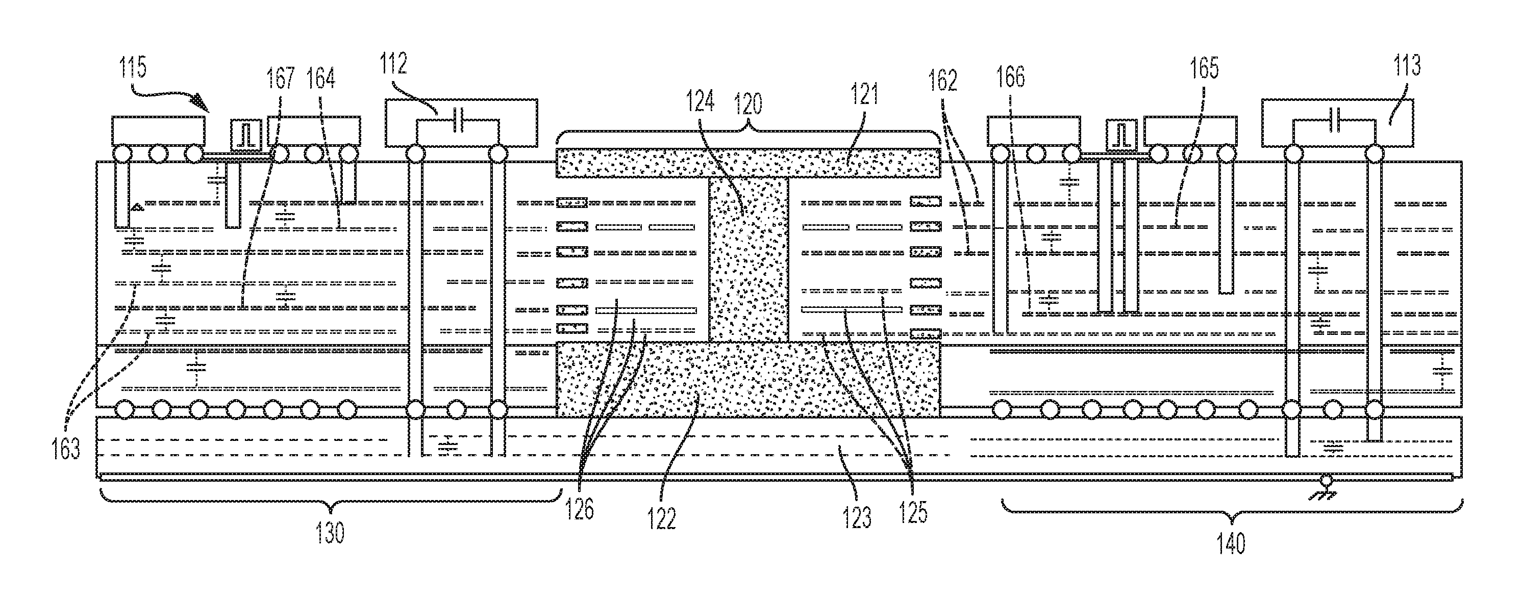
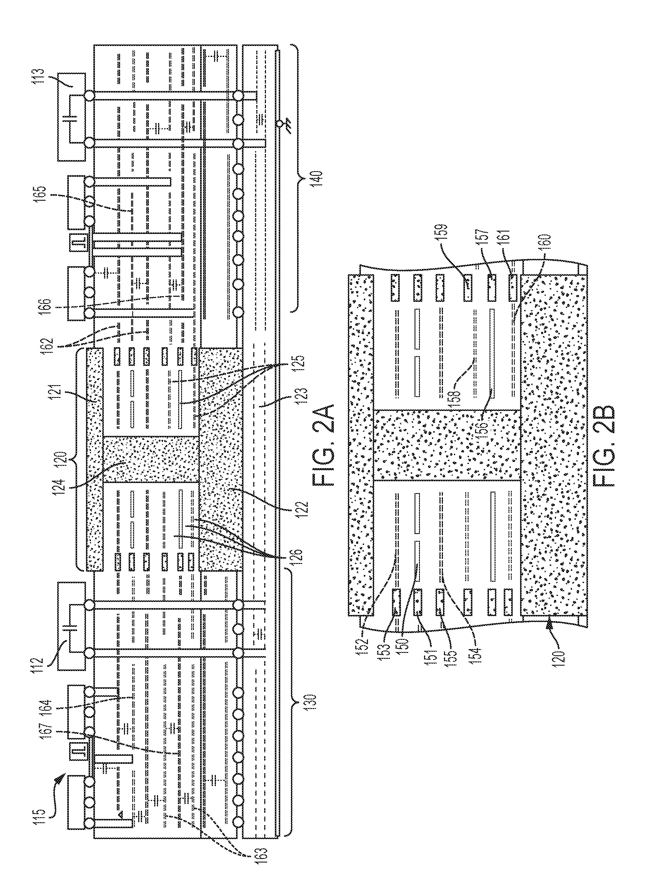
[0043] With reference to FIGS. 2A and 2B, components of the integrated DC/DC converter 115 are illustrated. As shown in FIG. 2A, the integrated DC/DC converter 115 includes a transformer area 120 that is interposed between an input section 130 and an output section 140. The input section 130 includes the discrete input capacitor 112 and the output section 140 includes the discrete output capacitor 113. The transformer area 120 includes a magnetic core top portion 121 that is formed of magnetic materials, a magnetic core bottom portion 122 that is disposed on a baseplate 123 and is formed of magnetic materials, a magnetic core pillar 124 that extends between central sections of the magnetic core top and bottom portions 121 and 122 and successive layers 125 at opposite sides of the magnetic core pillar 124. The successive layers 125 include layers of shield (i.e., metallic) and magnetic core materials, layers of windings and magnetic core materials and layers of shield and magnetic core materials, each of which are interleaved between dielectric material layers 126.
[0044] In accordance with embodiments, the magnetic core top and bottom portions 121 and 122 have similar widths, the magnetic core pillar 124 has a lesser width than the magnetic core top and bottom portions 121 and 122 and the successive layers 125 of the windings and the magnetic core materials extend outwardly to respective edges of the magnetic core top and bottom portions 121 and 122.
[0045] As shown in FIG. 2B, the successive layers 125 include a layer of primary winding materials 150 and magnetic core materials 151 as well as a layer of first primary shield materials 152 and magnetic core materials 153 above the layer of the primary winding materials 150 and the magnetic core materials 151 and a layer of second primary shield materials 154 and magnetic core materials 155 below the layer of the primary winding materials 150 and the magnetic core materials 151. In addition, the successive layers 125 include a layer of secondary winding materials 156 and magnetic core materials 157 as well as a layer of first secondary shield materials 158 and magnetic core materials 159 above the layer of the secondary winding materials 156 and the magnetic core materials 157 and a layer of second secondary shield materials 160 and magnetic core materials 161 below the layer of the secondary winding materials 156 and the magnetic core materials 157.
[0046] The layers of the first and second primary shield materials 152 and 154 extend continuously into the transformer area 120 from the discrete input capacitor 112 of the input section 130 and discontinuously correspond to layers of additional shield materials 162 (see FIG. 2A) of the discrete output capacitor 113 in the output section 140. The layers of the first and second secondary shield materials 158 and 160 extend continuously into the transformer area 120 from the discrete output capacitor 113 of the output section 140 and discontinuously correspond to layers of additional shield materials 163 (see FIG. 2A) of the discrete input capacitor 112 in the input section 130.
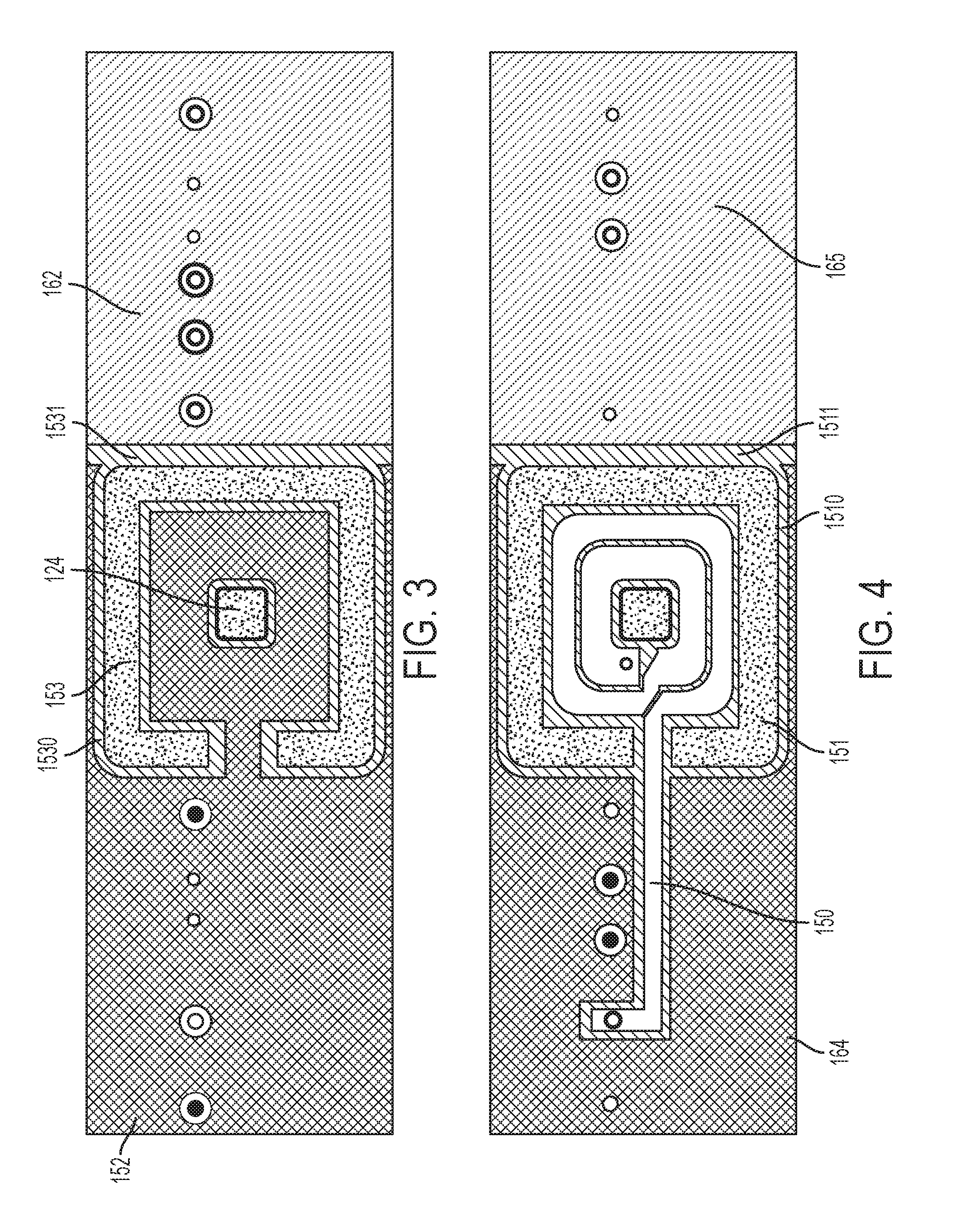
[0047] With reference to FIG. 3, in the layer of the first primary shield materials 152 and the magnetic core materials 153 above the layer of the primary winding materials 150 and the magnetic core materials 151, the magnetic core materials 153 form a reverse C-shape about the magnetic core pillar 124. In addition, the magnetic core materials 153 are surrounded by dielectric materials 1530 and are adjacent to a line of dielectric materials 1531. The line of dielectric materials 1531 separates the first primary shield materials 152 from the layers of the additional shield materials 162. The layer of the second primary shield materials 154 and the magnetic core materials 155 below the layer of the primary winding materials 150 and the magnetic core materials 151 are similarly formed.
[0048] With reference to FIG. 4, in the layer of the primary winding materials 150 and the magnetic core materials 151, the magnetic core materials 151 form a reverse C-shape about the magnetic core pillar 124. In addition, the magnetic core materials 151 are surrounded by dielectric materials 1510 and are adjacent to a line of dielectric materials 1511. The line of dielectric materials 1511 separates input capacitor shield materials 164 from output capacitor shield materials 165 (see FIG. 2A).
[0049] With reference to FIG. 5, in the layer of the first secondary shield materials 158 and the magnetic core materials 159 above the layer of the secondary winding materials 156 and the magnetic core materials 157, the magnetic core materials 159 form a C-shape about the magnetic core pillar 124. In addition, the magnetic core materials 159 are surrounded by dielectric materials 1590 and are adjacent to a line of dielectric materials 1591. The line of dielectric materials 1591 separates the first secondary shield materials 158 from the layers of the additional shield materials 163. The layer of the second secondary shield materials 160 and the magnetic core materials 161 below the layer of the secondary winding materials 156 and the magnetic core materials 157 are similarly formed.
[0050] With reference to FIG. 6, in the layer of the secondary winding materials 156 and the magnetic core materials 157, the magnetic core materials 157 form a C-shape about the magnetic core pillar 124. In addition, the magnetic core materials 157 are surrounded by dielectric materials 1570 and are adjacent to a line of dielectric materials 1571. The line of dielectric materials 1571 separates output capacitor shield materials 166 from input capacitor shield materials 167 (see FIG. 2A).
[0051] The output capacitor shield materials 165 may be similar materials as those of the layers of the first and second secondary shield materials 158 and 160. Similarly, the input capacitor shield materials 167 may be similar materials as those of the layers of the first and second primary shield materials 152 and 154.
[0052] In accordance with embodiment, all of the layers of the primary and secondary shield materials can occupy a same volume on separate layers only in the transformer area 120. This serves to reduce transformer feed-through capacitance (i.e., primary shields do not cross over to the secondary side and vice versa). In addition, layers of shield materials that are referenced to a highest DC voltage (either primary or secondary) may be extended under the transformer area 120.
[0053] While the disclosure is provided in detail in connection with only a limited number of embodiments, it should be readily understood that the disclosure is not limited to such disclosed embodiments. Rather, the disclosure can be modified to incorporate any number of variations, alterations, substitutions or equivalent arrangements not heretofore described, but which are commensurate with the spirit and scope of the disclosure. Additionally, while various embodiments of the disclosure have been described, it is to be understood that the exemplary embodiment(s) may include only some of the described exemplary aspects. Accordingly, the disclosure is not to be seen as limited by the foregoing description, but is only limited by the scope of the appended claims.
* * * * *
D00000
D00001
D00002
D00003
D00004
XML
uspto.report is an independent third-party trademark research tool that is not affiliated, endorsed, or sponsored by the United States Patent and Trademark Office (USPTO) or any other governmental organization. The information provided by uspto.report is based on publicly available data at the time of writing and is intended for informational purposes only.
While we strive to provide accurate and up-to-date information, we do not guarantee the accuracy, completeness, reliability, or suitability of the information displayed on this site. The use of this site is at your own risk. Any reliance you place on such information is therefore strictly at your own risk.
All official trademark data, including owner information, should be verified by visiting the official USPTO website at www.uspto.gov. This site is not intended to replace professional legal advice and should not be used as a substitute for consulting with a legal professional who is knowledgeable about trademark law.