Robot Having A Controller Protected For A Network Failure
Haddadin; Sami ; et al.
U.S. patent application number 16/094392 was filed with the patent office on 2019-05-02 for robot having a controller protected for a network failure. This patent application is currently assigned to Franka Emika GmbH. The applicant listed for this patent is Franka Emika GmbH. Invention is credited to Sami Haddadin, Bjorn Pietsch.
| Application Number | 20190126481 16/094392 |
| Document ID | / |
| Family ID | 58709436 |
| Filed Date | 2019-05-02 |

| United States Patent Application | 20190126481 |
| Kind Code | A1 |
| Haddadin; Sami ; et al. | May 2, 2019 |
ROBOT HAVING A CONTROLLER PROTECTED FOR A NETWORK FAILURE
Abstract
The invention relates to a robot having actuator-driven elements, which requires a desired operating voltage U.sub.B and/or a desired operating current I.sub.B in order to operate, comprising: a voltage and current source having an input interface, to which a primary voltage U.sub.P and a primary current I.sub.P are applied, wherein, during normal operation, the primary voltage U.sub.P is equal to a desired primary voltage U.sub.P,desired and the primary current I.sub.P is equal to a desired primary current I.sub.P,desired, and also having an output interface, to which an actual voltage U.sub.actual and an actual current I.sub.actual are supplied, wherein during normal operation: U.sub.actual=U.sub.B and I.sub.actual=I.sub.B, an energy store, which is integrated into the voltage and current source and which maintains the operating voltage U.sub.B and the operating current I.sub.B for a predefined period of time .DELTA.t following a failure or a drop in the primary voltage/primary current, a unit for monitoring the primary voltage U.sub.P applied to the input interface, wherein the unit is configured such that as soon as the applied primary voltage U.sub.P deviates by a predefined amount .DELTA.U from the desired primary voltage U.sub.P,desired, a stop signal is generated, and a control unit, which is connected to the unit and which is designed for controlling the robot and its actuator-driven elements, wherein the control unit is configured to control the robot with its elements into a predefined safe state upon receipt of the stop signal.
| Inventors: | Haddadin; Sami; (Hannover, DE) ; Pietsch; Bjorn; (Munchen, DE) | ||||||||||
| Applicant: |
|
||||||||||
|---|---|---|---|---|---|---|---|---|---|---|---|
| Assignee: | Franka Emika GmbH Munchen DE |
||||||||||
| Family ID: | 58709436 | ||||||||||
| Appl. No.: | 16/094392 | ||||||||||
| Filed: | April 25, 2017 | ||||||||||
| PCT Filed: | April 25, 2017 | ||||||||||
| PCT NO: | PCT/EP2017/059693 | ||||||||||
| 371 Date: | October 17, 2018 |
| Current U.S. Class: | 1/1 |
| Current CPC Class: | B25J 19/06 20130101; B25J 19/005 20130101; B25J 13/006 20130101; G05B 2219/34474 20130101; G05B 2219/34369 20130101; G05B 19/406 20130101; G05B 2219/25362 20130101; B25J 9/1674 20130101; G05B 2219/50082 20130101 |
| International Class: | B25J 9/16 20060101 B25J009/16; B25J 19/00 20060101 B25J019/00; B25J 13/00 20060101 B25J013/00; G05B 19/406 20060101 G05B019/406 |
Foreign Application Data
| Date | Code | Application Number |
|---|---|---|
| Apr 25, 2016 | DE | 10 2016 005 366.6 |
Claims
1. A robot having actuator-driven elements, the robot requiring a desired operating voltage U.sub.B and/or a desired operating current I.sub.B in order to operate, the robot comprising: a voltage and current source comprising: an input interface to which a primary voltage U.sub.P and a primary current I.sub.P are applied, wherein, during normal operation, the primary voltage U.sub.P is equal to a desired primary voltage U.sub.P,desired and the primary current I.sub.P is equal to a desired primary current I.sub.P,desired, and an output interface to which an actual voltage U.sub.actual and an actual current I.sub.actual are supplied, wherein during normal operation: U.sub.actual=UB and I.sub.actual=I.sub.B; an energy store integrated into the voltage and current source and configured to maintain the operating voltage U.sub.B and the operating current I.sub.B for a predefined period of time .DELTA.t following a failure or a drop in the primary voltage U.sub.P and/or primary current I.sub.P; a unit configured to monitor the primary voltage U.sub.P applied to the input interface and configured to generate a stop signal as soon as the applied primary voltage U.sub.P deviates by a predefined amount .DELTA.U from the desired primary voltage U.sub.P,desired; and a control unit connected to the unit and configured to control the robot and its actuator-driven elements, wherein the control unit is further configured to control the robot with its actuator-driven elements into a predefined safe state upon receipt of the stop signal.
2. The robot according to claim 1, in which actuators of the actuator-driven elements are connectable to the integrated energy store to recuperate electrical energy.
3. The robot according to claim 1, wherein the unit is configured in such a way that controlling the robot into the predefined safe state comprises a triggering of mechanical brakes of the actuator-driven elements.
4. The robot according to claim 1, in which the energy store comprises one or more capacitors, and/or one or more inductors, and/or one or more accumulators.
5. The robot according to claim 1, wherein the stop signal is transmitted as a symmetrical and encrypted data signal from the unit to the control unit via a data link configured to transmit symmetrical and encrypted data signals.
6. The robot according to claim 1, wherein the stop signal is transmitted as an optical signal from the unit to the control unit via an optical data link configured to transmit optical signals.
Description
CROSS-REFERENCE TO RELATED APPLICATIONS
[0001] This application is the U.S. National Phase of International Patent Application No. PCT/EP2017/059693, filed on 25 Apr. 2017, which claims benefit of German Patent Application No. 102016005366.6, filed on 25 Apr. 2016, the contents of which are incorporated herein by reference in their entirety.
BACKGROUND
Field
[0002] The invention relates to a robot having a controller which is protected against a power network failure (failure of the electrical energy required to operate the robot). For this purpose, the robot has advantageously movable, actuator-driven elements.
Related Art
[0003] Robots typically require electric power to operate. This power is supplied, particularly in the case of immobile robots, via an electric power supply unit of the robot, which is connected on the input side to an electric power source, typically to an electric power network. The electric power network or the electric power source may suffer failure for a number of reasons. When such a failure occurs, for functional safety reasons it must be ensured that the robot, i.e. its movable elements in particular, will enter a safe state. Such a state is meant to ensure that the robot will not become damaged, will not cause any damage in the area surrounding it, and will be operable immediately once the electric power supply is restored, if at all possible without any problems and without requiring intervention.
SUMMARY
[0004] The object of the invention is therefore to provide a robot that will enter a safe state, in particular with its moving elements, when a failure of the power supply occurs, and which will simply be ready to operate again once the network power supply is restored.
[0005] The invention will be clear from the features of the independent claims. Advantageous refinements and embodiments are the subject matter of the dependent claims. Other features, applications and advantages of the invention will be apparent from the following description, and from the elucidation of exemplary embodiments of the invention, which are depicted in the figure.
[0006] The object is attained by a robot having actuator-driven elements, which requires a desired operating voltage U.sub.B and/or a desired operating current I.sub.B in order to operate. The robot comprises a voltage and current source (i.e. a power supply unit) having an input interface, to which a primary voltage U.sub.P and a primary current I.sub.P are applied, wherein during normal operation the primary voltage U.sub.P is equal (in terms of control and noise tolerances) to a desired primary voltage U.sub.P,desired and the primary current I.sub.P is equal (in terms of control and noise tolerances) to a desired primary current I.sub.P,desired, and also having an output interface, to which an actual voltage U.sub.actual and an actual current I.sub.actual are applied, wherein during normal operation (in terms of control and noise tolerances), U.sub.actual=U.sub.B and I.sub.actual=IB, an energy store which is integrated into the voltage and current source and which, following a failure or a drop in the primary voltage/primary current, maintains the operating voltage U.sub.B and the operating current IB for a predefined period of time .DELTA.t, a unit for monitoring the primary voltage U.sub.P applied to the input interface, the unit being configured such that, as soon as the applied primary voltage U.sub.P deviates from the desired primary voltage U.sub.P,desired by a predefined amount .DELTA.U, a stop signal is generated, and a control unit which is connected to said monitoring unit and which is designed for controlling the robot and the actuator-driven elements thereof, the control unit being configured to control the robot and the elements thereof into a predefined safe state upon receipt of the stop signal.
[0007] The term "actuator-driven elements" is interpreted broadly in the present case, It includes essentially all movable, actuator-driven elements of the robot, for example, members of a robot manipulator, artificial limbs, drive wheels, etc.
[0008] The voltage and current source is preferably embodied as a power supply unit of the robot, with the robot being operated at a desired operating voltage U.sub.B and/or a desired operating current I.sub.B, which is supplied to the output interface of the voltage and current source. The input interface of the voltage and current source is advantageously connected to an electric power network, typically a low voltage network (for example, a 230-240V power network or a 400-420V three-phase alternating current network). The voltage and current source advantageously converts the primary voltage U.sub.P which is applied to the input side to the actual voltage U.sub.actual which is supplied to the output interface. Typically, U.sub.actual<U.sub.P.
[0009] During normal robot operation, the actual voltage U.sub.actual supplied to the output interface is equal to the desired operating voltage UB (U.sub.actual=U.sub.B). In addition, during normal robot operation, the actual current I.sub.actual supplied to the output interface is equal to the desired operating current I.sub.B (I.sub.actual=I.sub.B).
[0010] According to the invention, the voltage and current source is further equipped with an energy store, which is integrated into the voltage and current source and which is designed and configured such that, following a failure or a drop in the primary voltage U.sub.P or the primary current I.sub.P at the input interface, the operating voltage U.sub.B and the operating current I.sub.B at the output interface are maintained for a predefined period of time .DELTA.t. The energy store is preferably equipped with one or more capacitors and/or one or more inductors and/or one or more accumulators for energy storage. The term "inductors" in the present case includes, for example, inductors, coils, transformers, etc. The dimensions of the energy store are advantageously dependent upon the amount of energy required by the robot to bring the robot from any dynamic state (any possible dynamic state of the operator) into a safe state.
[0011] The term "safe state" is interpreted broadly in the present case. It includes essentially any state of the robot that can be detected by means of sensors. In particular, the term includes a predefined state of the movable elements of the robot, in particular a deceleration of all the movable elements of the robot into a predefined pose or a deceleration of all the movable elements of the robot into said state without a predefined pose. The "safe state" may further include, for example, electrical states and data-related states of the robot. For instance, the safe state may include a data backup, etc.
[0012] Advantageously, once the stop signal has been received, the control unit quasi instantaneously initiates the establishment of the safe state, in particular initiating a deceleration process of the actuator-driven movable elements of the robot into a mechanical safe state. The safe state is advantageously predefined appropriately depending upon the task set for the robot, and advantageously meets the condition that, during the establishment of the safe state, in particular by decelerating the movable elements of the robot into the safe mechanical state, the robot does not present a threat to its environment or to itself.
[0013] The dimensions of the energy store are advantageously selected such that in the event of a total failure of the primary voltage U.sub.P/primary current I.sub.P applied to the input interface it is ensured that the operating voltage U.sub.B and the operating current I.sub.B at the output interface are maintained for the predefined period of time .DELTA.t. The period of time .DELTA.t is advantageously a required period of time during which the robot can be brought from any state into a safe state.
[0014] Appropriate dimensions of the energy store thus ensure that, even with a total failure of the voltage or current supply to the input side of the voltage and current source, it is always ensured that the robot can be transferred from any state into a safe state. The state referred to as "any" state is any element of the set of all the states that the robot is able to occupy.
[0015] One advantageous refinement of the proposed robot is characterized in that actuators of the driven elements are designed for the recuperation of electric power and can be connected to the integrated energy store. Thus, it is advantageously possible to convert kinetic energy of the movable elements of the robot during the deceleration process into electrical energy and to use this energy to increase the energy stored in the energy store.
[0016] One advantageous refinement of the proposed robot is characterized in that the unit is designed such that the controlling of the robot into the predefined safe state comprises a triggering of the mechanical deceleration of the driven elements. Advantageously, the mechanical brake(s) is/are triggered only when the robot has been decelerated by actuators into a dynamic state which is preferably characterized by the sum of the kinetic energy of some or all of the movable elements of the robot, which is less than one predefined boundary kinetic energy. It can thereby be ensured that an abrupt intervention by mechanical brakes takes place only when no mechanical or other damage to the robot will be caused by engagement of the mechanical brakes. Prior to this point, the robot, i.e. its actuator-driven movable elements, is preferably decelerated by actuators. This refinement increases the availability of the robot system, since a firm response by mechanical brakes with the associated risk of mechanical damage is generally avoided.
[0017] According to one advantageous refinement of the proposed robot, the stop signal is transmitted as an encrypted data signal via the symmetrically configured data, link from the unit to the control unit. Further advantageously, the stop signal is an optical signal and the data link is configured for transmitting optical signals.
[0018] In principle, any wired or fiber optic transmission method is suitable for this transmission: analog voltage, digital signal (direct or modulated), communication protocol. The latter two groups are optically transmittable; this is advantageous because isolation is simultaneously achieved as a result (i.e., detection at the input interface with high voltage, processing at the output interface typically with lower voltage).
[0019] The stop signal is advantageously a high priority signal to the control unit of the robot indicating that a power failure at the output interface is imminent.
[0020] Advantageously, when a drop in voltage occurs at the output interface, mechanical brakes are engaged immediately so that the movable elements of the robot are decelerated almost instantaneously. Thus, a safe initiation of a deceleration process is always ensured, in this case, a reliable implementation of the energy storage function is not necessary, because the mechanical deceleration process is initiated independently of the energy that is available in the energy store.
[0021] Further advantages, features and details will be apparent from the following description, in which at least one exemplary embodiment is described in detail, with reference to the drawings where appropriate. The same, similar and/or functionally equivalent parts are provided with the same reference signs.
BRIEF DESCRIPTION OF THE DRAWINGS
[0022] In the drawings:
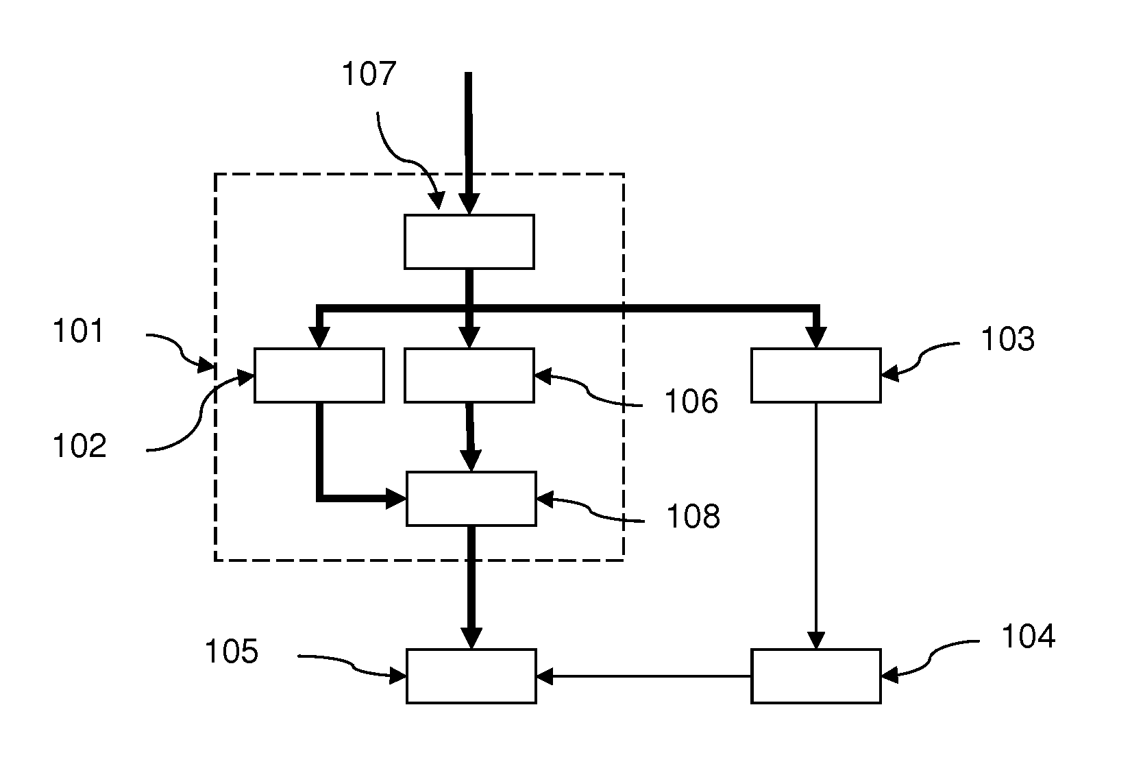
[0023] FIG. 1 shows a schematic diagram of one embodiment of the proposed robot.
DETAILED DESCRIPTION
[0024] FIG. 1 shows a schematic diagram of one embodiment of the proposed robot having actuator-driven elements 105, which requires a desired operating voltage U.sub.B and/or a desired operating current I.sub.B for operation. The robot comprises a voltage and current source 101 having an input interface 107 to which a primary voltage U.sub.P and a primary current I.sub.P are applied, wherein during normal operation, the primary voltage U.sub.P is equal to a desired primary voltage U.sub.P,desired and the primary current I.sub.P is equal to a desired primary current I.sub.P,desired, and also having an output interface 108 to which an actual voltage U.sub.actual and an actual current I.sub.actual are applied, wherein during normal operation: U.sub.actual=U.sub.B and I.sub.actual=I.sub.B.
[0025] Voltage and current source 101 comprises an energy store 102 integrated therein, in the present case comprising a plurality of capacitors which, following a failure or a drop in the primary voltage/primary current, maintain the operating voltage U.sub.B and the operating current I.sub.B at the output interface 108 for a predefined period of time .DELTA.t.
[0026] Voltage and current source 101 further comprises a transformer 106, which transforms the primary voltage U.sub.P supplied to the input interface 107 into a low-voltage range and supplies it to output interface 108 as the actual voltage U.sub.actual.
[0027] The robot further comprises a unit 103 for monitoring the primary voltage U.sub.P applied to input interface 107, with the unit 103 being designed in such a way that as soon as the applied primary voltage U.sub.P deviates from the desired primary voltage U.sub.P,desired by a predetermined amount .DELTA.U, a stop signal is generated.
[0028] Finally, the robot comprises a control unit 104, which is connected to unit 103 and is designed for controlling the robot and its actuator-driven elements 105, with the control unit 104 being configured to control the robot with its elements 105 into a predefined safe state upon receipt of the stop signal.
[0029] In FIG. 1, the load current paths are indicated by bold arrows. The thinner arrows proceeding from unit 103 to control unit 104 and from there to the actuator-driven elements of the robot are data lines. Advantageously, the stop signal is an optical signal and the data lines are configured as optical fibers.
[0030] Although the invention has been further illustrated and described in detail by way of preferred exemplary embodiments, the invention is not restricted by the disclosed examples, and other variations may be derived from said examples by those skilled in the art, without departing from the scope of the invention. It is therefore clear that a multitude of possible variations exists. It is also clear that cited, exemplified embodiments are actually merely examples, and are not to be construed in any way as limiting the scope, applicability, or configuration of the invention. Rather, the foregoing description and the description of the FIGS. enable a person skilled in the art to implement the exemplary embodiments, and those skilled in the art with knowledge of the disclosed inventive concept may make various modifications, for example as to the function or the arrangement of individual elements cited in an exemplary embodiment, without departing from the scope as defined by the claims and their legal equivalents, such as the detailed explanations in the description.
LIST OF REFERENCE SIGNS
[0031] 101 voltage and current source/power supply unit [0032] 102 energy store integrated into the voltage and current source [0033] 103 unit [0034] 104 control unit [0035] 105 actuator-driven elements of the robot [0036] 106 transformer [0037] 107 input interface [0038] 108 output interface
* * * * *
D00000
D00001
XML
uspto.report is an independent third-party trademark research tool that is not affiliated, endorsed, or sponsored by the United States Patent and Trademark Office (USPTO) or any other governmental organization. The information provided by uspto.report is based on publicly available data at the time of writing and is intended for informational purposes only.
While we strive to provide accurate and up-to-date information, we do not guarantee the accuracy, completeness, reliability, or suitability of the information displayed on this site. The use of this site is at your own risk. Any reliance you place on such information is therefore strictly at your own risk.
All official trademark data, including owner information, should be verified by visiting the official USPTO website at www.uspto.gov. This site is not intended to replace professional legal advice and should not be used as a substitute for consulting with a legal professional who is knowledgeable about trademark law.