Substrate Treatment Apparatus
SHINOZAKI; Hiroyuki
U.S. patent application number 16/092637 was filed with the patent office on 2019-05-02 for substrate treatment apparatus. The applicant listed for this patent is EBARA CORPORATION. Invention is credited to Hiroyuki SHINOZAKI.
| Application Number | 20190126430 16/092637 |
| Document ID | / |
| Family ID | 60115849 |
| Filed Date | 2019-05-02 |


View All Diagrams
| United States Patent Application | 20190126430 |
| Kind Code | A1 |
| SHINOZAKI; Hiroyuki | May 2, 2019 |
SUBSTRATE TREATMENT APPARATUS
Abstract
A substrate processing apparatus has a table on which a polishing surface for polishing a substrate is provided, and a discharge suction section which has a discharge port which communicates with a fluid supply source and through which a fluid is discharged to the polishing surface and a suction opening which communicates with a vacuum source and through which the fluid existing on the polishing surface is sucked.
| Inventors: | SHINOZAKI; Hiroyuki; (Tokyo, JP) | ||||||||||
| Applicant: |
|
||||||||||
|---|---|---|---|---|---|---|---|---|---|---|---|
| Family ID: | 60115849 | ||||||||||
| Appl. No.: | 16/092637 | ||||||||||
| Filed: | March 14, 2017 | ||||||||||
| PCT Filed: | March 14, 2017 | ||||||||||
| PCT NO: | PCT/JP2017/010158 | ||||||||||
| 371 Date: | October 10, 2018 |
| Current U.S. Class: | 1/1 |
| Current CPC Class: | H01L 21/67219 20130101; B24B 37/20 20130101; B24B 55/06 20130101; B24B 53/12 20130101; B24B 37/32 20130101; B24B 57/02 20130101; B24B 53/017 20130101 |
| International Class: | B24B 37/32 20060101 B24B037/32; B24B 37/20 20060101 B24B037/20; B24B 53/12 20060101 B24B053/12 |
Foreign Application Data
| Date | Code | Application Number |
|---|---|---|
| Apr 21, 2016 | JP | 2016-085184 |
Claims
1. A substrate processing apparatus comprising: a table on which a polishing surface for polishing a substrate is provided; and a discharge suction section which includes a discharge port which communicates with a fluid supply source and through which a fluid is discharged to the polishing surface and a suction opening which communicates with a vacuum source and through which the fluid existing on the polishing surface is sucked.
2. The substrate processing apparatus according to claim 1, wherein a gas is discharged from the discharge port, and a liquid on the polishing surface is vibrated or disturbed.
3. The substrate processing apparatus according to claim 1, wherein the table is rotatable, the discharge port is disposed on a downstream side of the suction opening in a rotation direction of the table, and a liquid is supplied from the discharge port.
4. The substrate processing apparatus according to claim 3, wherein the liquid discharged from the discharge port is a processing solution for processing a substrate.
5. The substrate processing apparatus according to claim 1, wherein the table is rotatable, the discharge port is disposed on an upstream side of the suction opening in a rotation direction of the table, and a liquid is supplied from the discharge port.
6. The substrate processing apparatus according to claim 1, wherein a flow path leading to the discharge port is inclined in a direction opposite to a direction of the suction opening.
7. The substrate processing apparatus according to claim 1, wherein a distance between the discharge port and the suction opening is equal to or more than a lower limit distance within which a range of a thin liquid film on the polishing surface can be expanded by a fluid flow supplied from the discharge port.
8. The substrate processing apparatus according to claim 1, wherein a flow path leading to the discharge port is inclined in a direction of the suction opening.
9. The substrate processing apparatus according to claim 1, wherein a distance between the discharge port and the suction opening is equal to or less than an upper limit distance at which the polishing surface is hit by the fluid discharged from the discharge port to cause the dust and/or debris to float and then the floated dust and/or debris can be sucked from the suction opening.
10. The substrate processing apparatus according to claim 1, wherein the discharge port and the suction opening are positioned on an approximately identical plane.
11. The substrate processing apparatus according to claim 1, wherein a plurality of the discharge ports are disposed in a radial direction of the table.
12. The substrate processing apparatus according to claim 1, further comprising: a polishing liquid supply section which supplies a polishing liquid to the polishing surface; and a substrate holding section which holds the substrate, wherein the discharge suction section is disposed on a downstream side of a polishing liquid supply nozzle in the rotation direction of the table and is disposed on an upstream side of the substrate holding section in the rotation direction of the table.
13. The substrate processing apparatus according to claim 1, further comprising: a dresser for performing dressing of the polishing surface; and a polishing liquid supply section which supplies a polishing liquid to the polishing surface, wherein the discharge suction section is disposed on a downstream side of the dresser in the rotation direction of the table and is disposed on an upstream side of the polishing liquid supply section in the rotation direction of the table.
14. The substrate processing apparatus according to claim 1, further comprising: a substrate holding section which holds the substrate; and a dresser for performing dressing of the polishing surface, wherein the discharge suction section is disposed on a downstream side of the substrate holding section in the rotation direction of the table and is disposed on an upstream side of the dresser in the rotation direction of the table.
Description
RELATED APPLICATION
[0001] This application claims the benefit of Patent Application No. 2016-85184, filed on Apr. 21, 2016 in Japan, the contents of which are incorporated herein by reference.
TECHNICAL FIELD
[0002] The present technique relates to a substrate processing apparatus.
BACKGROUND ART
[0003] Conventionally, a substrate processing apparatus (for example, a Chemical Mechanical Polishing (CMP) apparatus) includes a nozzle (so-called admizer) for injecting high-pressure washing water, and it is known that the high-pressure washing water is injected into a polishing pad surface after completion of polishing or at the time of water polishing at the end of polishing (for example, refer to Patent Literature 1). A technique of providing a suction dedicated arm beside a rinse supply arm is also known (refer to Patent Literature 2).
CITATION LIST
Patent Literature
[0004] Patent Literature 1: JP 2010-50436 A [0005] Patent Literature 2: US Application Publication No. 2016/0016283
SUMMARY OF INVENTION
[0006] A substrate processing apparatus of an embodiment includes: a table on which a polishing surface for polishing a substrate is provided; and a discharge suction section which includes a discharge port which communicates with a fluid supply source and through which a fluid is discharged to the polishing surface and a suction opening which communicates with a vacuum source and through which the fluid existing on the polishing surface is sucked.
BRIEF DESCRIPTION OF DRAWINGS
[0007] FIG. 1 is a plan view illustrating the overall structure of a substrate processing apparatus 100 common to the embodiments of the present technique.
[0008] FIG. 2 is a schematic plan view of a first polishing unit 3A according to a first embodiment.
[0009] FIG. 3 is a schematic perspective view of a discharge suction section 34A according to the first embodiment.
[0010] FIG. 4 is a schematic front view of an arm 90 according to the first embodiment.
[0011] FIG. 5 is a sectional view taken along line A-A in FIG. 4.
[0012] FIG. 6 is a sectional view taken along line B-B in FIG. 4.
[0013] FIG. 7 is a sectional view taken along line C-C in FIG. 5.
[0014] FIG. 8 is a bottom view of the arm 90 according to the first embodiment.
[0015] FIG. 9 is a sectional view taken along line C-C of an arm 90-1 according to a first modification example of the first embodiment.
[0016] FIG. 10 is a sectional view taken along line C-C of an arm 90-2 according to a second modification example of the first embodiment.
[0017] FIG. 11 is a sectional view taken along line C-C of an arm 90-3 according to a third modification example of the first embodiment.
[0018] FIG. 12 is a schematic perspective view of a discharge suction section 34Ab according to a second embodiment.
[0019] FIG. 13 is a schematic front view of an arm 90b according to the second embodiment.
[0020] FIG. 14 is a sectional view taken along line D-D in FIG. 13.
[0021] FIG. 15 is a sectional view taken along line E-E in FIG. 14.
[0022] FIG. 16 is a sectional view taken along line F-F in FIG. 15.
[0023] FIG. 17 is a bottom view of the arm 90b according to the second embodiment.
[0024] FIG. 18 is a schematic plan view of a first polishing unit 3A according to a third embodiment.
[0025] FIG. 19 is a schematic perspective view of a discharge suction section 34Ac according to the third embodiment.
[0026] FIG. 20 is a schematic front view of an arm 90c of the third embodiment.
[0027] FIG. 21 is a sectional view taken along line G-G in FIG. 20.
[0028] FIG. 22 is a sectional view taken along line H-H in FIG. 21.
[0029] FIG. 23 is a sectional view taken along line I-I in FIG. 22.
[0030] FIG. 24 is a bottom view of the arm 90c according to the third embodiment.
[0031] FIG. 25 is a table showing pattern examples of various fluids discharged from a first discharge port and a second discharge port according to the third embodiment.
[0032] FIG. 26 is a sectional view taken along line H-H of an arm 90c-1 according to a first modification example according to the third embodiment.
[0033] FIG. 27 is a sectional view taken along line H-H of an arm 90c-2 according to a second modification example according to the third embodiment.
[0034] FIG. 28 is a sectional view taken along line H-H of an arm 90c-3 according to a third modification example according to the third embodiment.
[0035] FIG. 29 is a sectional view taken along line H-H of an arm 90c-4 according to a fourth modification example according to the third embodiment.
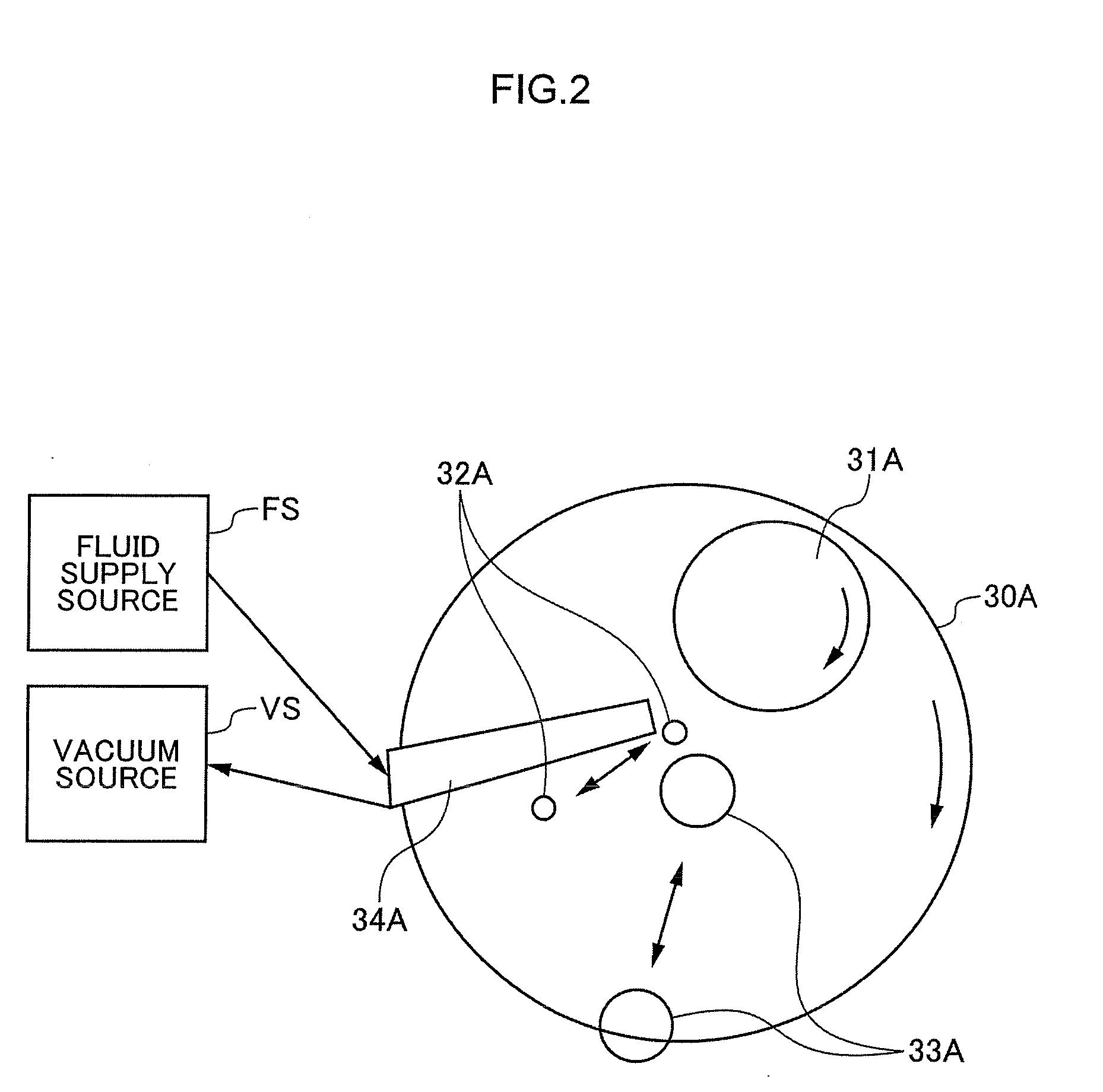
[0036] FIG. 30 is a sectional view taken along line H-H of an arm 90c-5 according to a fifth modification example according to the third embodiment.
[0037] FIG. 31 is a schematic plan view of a first polishing unit 3A according to a fourth embodiment.
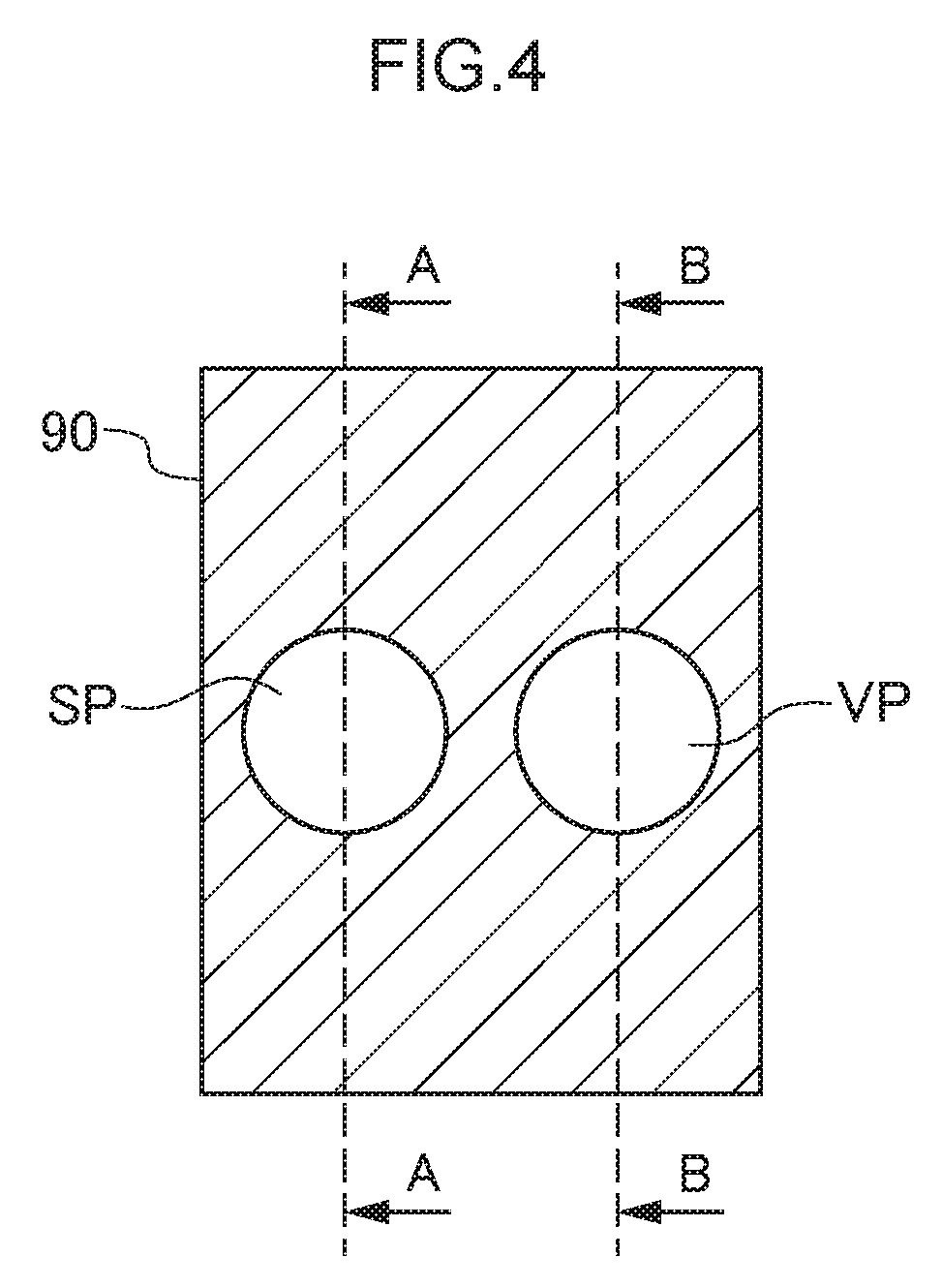
[0038] FIG. 32 is a sectional view of an arm 90d according to the fourth embodiment.
[0039] FIG. 33 is a table showing pattern examples of various fluids discharged from a first discharge port and a second discharge port according to the fourth embodiment.
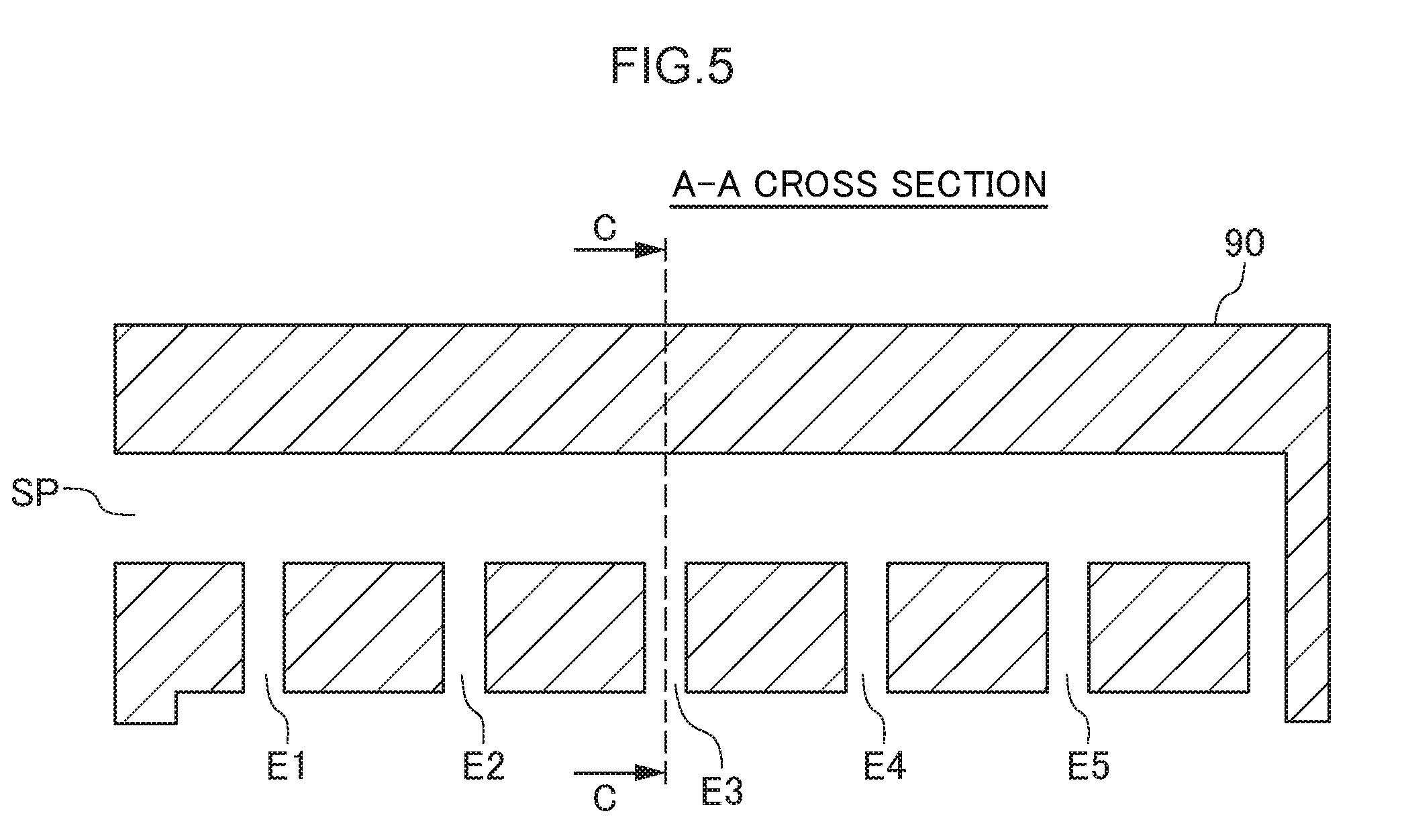
[0040] FIG. 34 is a schematic plan view of a first polishing unit 3A according to a fifth embodiment.
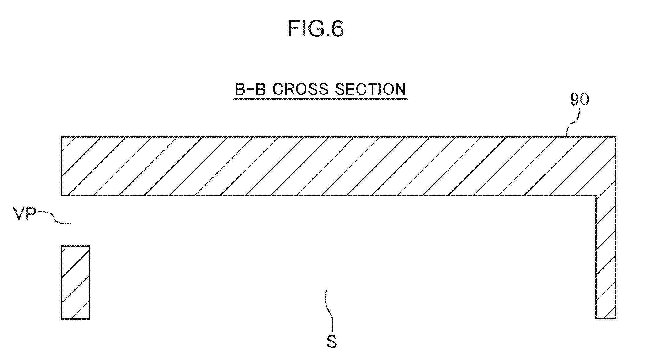
[0041] FIG. 35 is a sectional view of an arm 90e according to the fifth embodiment.
[0042] FIG. 36 is a table showing pattern examples of various fluids discharged from a discharge port according to the fifth embodiment.
[0043] FIG. 37 is a schematic plan view of the first polishing unit 3A according to Modification Example 1 of a shape of the discharge suction section.
[0044] FIG. 38 is a schematic plan view of the first polishing unit 3A according to Modification Example 2 of the shape of the discharge suction section.
[0045] FIG. 39 is a schematic plan view of the first polishing unit 3A according to Modification Example 1 in disposition of the discharge suction section.
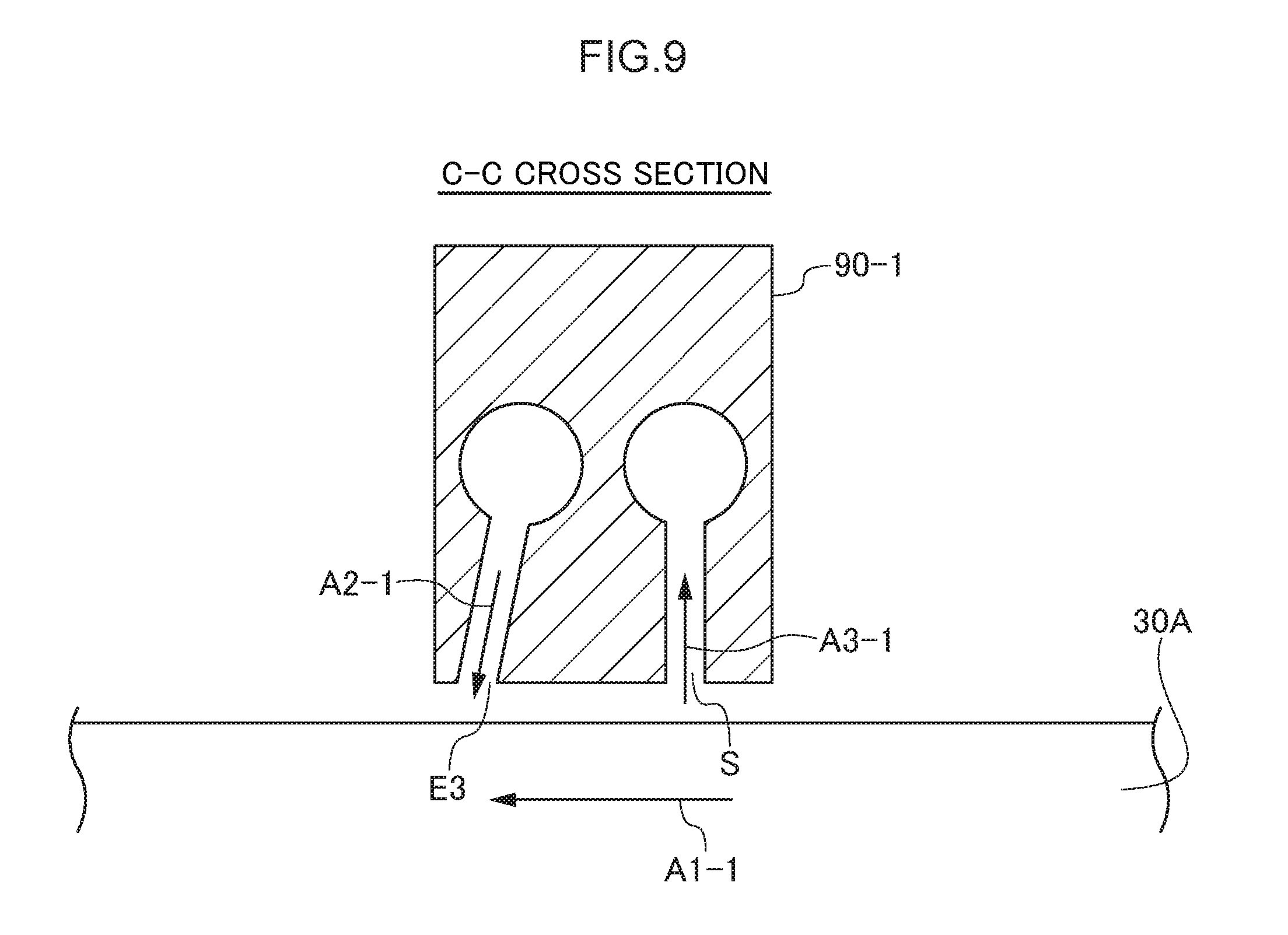
[0046] FIG. 40 is a schematic plan view of the first polishing unit 3A according to Modification Example 2 in disposition of the discharge suction section.
DESCRIPTION OF EMBODIMENTS
[0047] In the technique of Patent Literature 1, small dust and debris can not be removed due to influences (boundary layer) of a water film on the polishing pad surface. The small dust and/or debris can be removed by the technique of Patent Literature 2. However, a moment for supporting a suction member is increased by a suction force, and thus, there is a problem that it is difficult to maintain a gap between the suction member and a table.
Embodiment
[0048] It is preferable to provide a substrate processing apparatus capable of improving removal efficiency of dust and/or debris while maintaining the gap between the suction member and the table.
[0049] A substrate processing apparatus according to a first aspect of an embodiment includes a table on which a polishing surface for polishing a substrate is provided, and a discharge suction section which includes a discharge port which communicates with a fluid supply source and through which a fluid is discharged to the polishing surface and a suction opening which communicates with a vacuum source and through which the fluid existing on the polishing surface is sucked.
[0050] According to this configuration, a force in a polishing surface direction is applied to the discharge suction section by a suction pressure. However, the discharge suction section is supported by a discharge pressure by which the fluid is discharged, and thus, a narrow gap can be maintained between the discharge suction section and the table. In this way, the narrow gap can be maintained, and thus, removal efficiency of dust and/or debris can be improved.
[0051] The substrate processing apparatus according to a second aspect of the embodiment is the substrate processing apparatus according to the first aspect, wherein a gas is discharged from the discharge port, and a liquid on the polishing surface is vibrated or disturbed.
[0052] According to this configuration, a liquid film on the polishing surface is vibrated by a supply of the gas, the dust or the debris floats, and the removal efficiency of small dust and/or debris can be improved.
[0053] The substrate processing apparatus according to a third aspect of the embodiment is the substrate processing apparatus according to the first aspect, wherein the table is rotatable, the discharge port is disposed on a downstream side of the suction opening in a rotation direction of the table, and a liquid is supplied from the discharge port.
[0054] According to this configuration, the liquid is supplied to the polishing surface, and thus, drying of the polishing surface can be prevented.
[0055] The substrate processing apparatus according to a fourth aspect of the embodiment is the substrate processing apparatus according to the third aspect, wherein the liquid discharged from the discharge port is a processing solution for processing a substrate.
[0056] According to this configuration, the processing solution for processing the substrate can be supplied, and the processing solution can be renewed.
[0057] The substrate processing apparatus according to a fifth aspect of the embodiment is the substrate processing apparatus according to the first aspect, wherein the table is rotatable, the discharge port is disposed on an upstream side of the suction opening in a rotation direction of the table, and a liquid is supplied from the discharge port.
[0058] According to this configuration, when the liquid film of the polishing surface is thinned, the liquid is supplied before the suction from the suction opening is performed, and thus, the polishing surface can be prevented from drying.
[0059] The substrate processing apparatus according to a sixth aspect of the embodiment is the substrate processing apparatus according to any one of the first to fifth aspects, wherein a flow path leading to the discharge port is inclined in a direction opposite to a direction of the suction opening.
[0060] According to this configuration, a fluid flow supplied from the discharge port has a velocity component in a direction away from the suction opening, and thus, the liquid on the polishing surface is extruded by a gas flow supplied from the discharge port in a direction away from the suction opening, and a suction range can be expanded by the suction opening.
[0061] The substrate processing apparatus according to a seventh aspect of the embodiment is the substrate processing apparatus according to any one of the first to sixth aspects, wherein a distance between the discharge port and the suction opening is equal to or more than a lower limit distance within which a range of a thin liquid film on the polishing surface can be expanded by the fluid flow supplied from the discharge port.
[0062] According to this configuration, the range of the thin liquid film on the polishing surface can be expanded by the fluid flow supplied from the discharge port, and thus, the suction range by the suction opening expands as much as the liquid film is thinned, and thus, the dust and/or debris can be sucked in a wide area at one time.
[0063] The substrate processing apparatus according to an eighth aspect of the embodiment is the substrate processing apparatus according to any one of the first to fifth aspects, wherein a flow path leading to the discharge port is inclined in a direction of the suction opening.
[0064] According to this configuration, the gas flow supplied from the discharge port has the velocity component toward the suction opening, the fluid discharged from the discharge port hits the polishing surface, and thus, the dust and/or debris floats and can be extruded to the suction opening. Accordingly, the dust and/or debris can be effectively sucked from a suction opening S, and collection efficiency of the dust and/or debris can be improved.
[0065] The substrate processing apparatus according to a ninth aspect of the embodiment is the substrate processing apparatus according to any one of the first to fifth and the eighth aspects, wherein a distance between the discharge port and the suction opening is equal to or less than an upper limit distance at which the polishing surface is hit by the fluid discharged from the discharge port to cause the dust and/or debris to float and then the floated dust and/or debris can be sucked from the suction opening.
[0066] According to this configuration, the polishing surface is hit by the fluid discharged from the discharge port to cause the dust and/or debris to float and then the dust and/or debris can be sucked from the adjacent suction opening, and thus, the collection efficiency of the dust and/or debris can be improved.
[0067] The substrate processing apparatus according to a tenth aspect of the embodiment is the substrate processing apparatus according to any one of the first to ninth aspects, wherein the discharge port and the suction opening are positioned on an approximately identical plane.
[0068] According to this configuration, a levitation force from the polishing surface generated by the discharge of the fluid and an adsorption force to the polishing surface generated by the suction of the fluid are easily balanced with each other, and a gap with the table is easily maintained.
[0069] The substrate processing apparatus according to an eleventh aspect of the embodiment is the substrate processing apparatus according to any one of the first to tenth aspects, wherein a plurality of the discharge ports are disposed in a radial direction of the table.
[0070] According to this configuration, forces are balanced with each other in the radial direction of the table by the discharge pressures from the discharge ports and the suction pressure, a posture of the discharge suction section can be stabilized in the radial direction of the table, and a narrow gap between the discharge suction section and the table can be stably maintained.
[0071] The substrate processing apparatus according to a twelfth aspect of the embodiment is the substrate processing apparatus according to any one of the first to eleventh aspects further including a polishing liquid supply section which supplies a polishing liquid to the polishing surface and a substrate holding section which holds the substrate, wherein the discharge suction section is disposed on a downstream side of a polishing liquid supply nozzle in the rotation direction of the table and is disposed on an upstream side of the substrate holding section in the rotation direction of the table.
[0072] According to this configuration, the discharge suction section can also function as an admizer to wash away polishing debris, abrasive grain, or the like remaining on the polishing surface by a high-pressure fluid, and thus, it is not necessary to separately provide the admizer and a cost can be suppressed. That is, more preferable dressing, that is, regeneration of the polishing surface can be achieved by cleaning of the polishing surface by a fluid pressure of the discharge suction section and dressing of the polishing surface by a dresser which is a mechanical contact.
[0073] The substrate processing apparatus according to a thirteenth aspect of the embodiment is the substrate processing apparatus according to any one of the first to eleventh aspects further including a dresser for performing dressing of the polishing surface and a polishing liquid supply section which supplies a polishing liquid to the polishing surface, wherein the discharge suction section is disposed on a downstream side of the dresser in the rotation direction of the table and is disposed on an upstream side of the polishing liquid supply section in the rotation direction of the table.
[0074] According to this configuration, dust generated by the dressing of the polishing surface can be effectively collected. In addition, the discharge suction section collects the dust generated by the polishing of the dressing of the polishing surface, immediately after the polishing, and thus, diffusion of the dust can be prevented.
[0075] The substrate processing apparatus according to a fourteenth aspect of the embodiment is the substrate processing apparatus according to any one of the first to eleventh aspects further including a substrate holding section which holds the substrate and a dresser for performing dressing of the polishing surface, wherein the discharge suction section is disposed on a downstream side of the substrate holding section in the rotation direction of the table and is disposed on an upstream side of the dresser in the rotation direction of the table.
[0076] According to this configuration, the dust and/or debris generated by polishing of the substrate holding section can be effectively collected. In addition, the discharge suction section collects the dust and/or debris generated by the polishing of the substrate holding section, immediately after the polishing, and thus, diffusion of the dust and/or debris can be prevented.
[0077] Hereafter, each embodiment will be described with reference to the drawings. For example, a substrate processing apparatus 100 according to each embodiment is a polishing apparatus which polishes a substrate. In each embodiment, a wafer will be described as an example of the substrate. FIG. 1 is a plan view illustrating the overall structure of the substrate processing apparatus 100 common to the embodiments of the present technique. As illustrated in FIG. 1, the substrate processing apparatus 100 includes an approximately rectangular housing 1, and the inside of the housing 1 is partitioned into a load/unload section 2, a polishing section 3, and a cleaning section 4 by partition walls 1a and 1b. The load/unload section 2, the polishing section 3, and the cleaning section 4 are assembled separately and evacuated independently. The cleaning section 4 is partitioned into a first cleaning chamber 190, a first transfer chamber 191, a second cleaning chamber 192, a second transfer chamber 193, and a drying chamber 194. In addition, the substrate processing apparatus 100 has a controller 5 which controls a substrate processing operation.
[0078] The load/unload section 2 includes two or more (four in the present embodiment) front load sections 20 on which a wafer cassette which stocks a large number of wafers (substrates) is placed. The front load sections 20 are disposed to be adjacent to the housing 1 and are arranged along a width direction (a direction perpendicular to a longitudinal direction) of the substrate processing apparatus 100. An open cassette, a Standard Manufacturing Interface (SMIF) pod, or a Front Opening Unified Pod (FOUP) can be mounted in the front load section 20. Here, the SMIF and FOUP are airtight containers which accommodate the wafer cassette inside thereof and cover the wafer cassette with a partition wall so as to hold an environment independent of an external space.
[0079] In addition, in the load/unload section 2, a traveling mechanism 21 is laid along a row of the front load sections 20, and a transfer robot (loader) 22 which is movable along an arrangement direction of the wafer cassettes is installed on the traveling mechanism 21. The transfer robot 22 moves on the traveling mechanism 21 and thus, can access the wafer cassette mounted on the front load section 20. The transfer robot 22 includes two hands on the upper portion and lower portion, the upper hand is used to return a processed wafer to the wafer cassette, the lower hand is used to extract the wafer before processing from the wafer cassette, and thus, upper and lower hands can be used differently. Moreover, the lower hand of the transfer robot 22 rotates about an axis of the lower hand and is configured so as to be able to reverse the wafer.
[0080] The load/unload section 2 is an area where it is necessary to keep the cleanest state, and thus, the inside of the load/unload section 2 is always maintained at a higher pressure than any of the outside of the substrate processing apparatus 100, the polishing section 3, and the cleaning section 4. Slurry is used as a polishing liquid in the polishing section 3, and thus, the polishing section 3 is the dirtiest area. Accordingly, a negative pressure is formed inside the polishing section 3, and the pressure is maintained to be lower than an internal pressure of the cleaning section 4. A filter fan unit (not shown) having a clean air filter such as a HEPA filter, an ULPA filter, or a chemical filter is provided in the load/unload section 2, and thus, clean air in which particles, toxic vapors, and toxic gases are removed is constantly blown out from the filter fan unit.
[0081] The polishing section 3 is an area where polishing (planarization) of the wafer is performed, and includes a first polishing unit 3A, a second polishing unit 3B, a third polishing unit 3C, and a fourth polishing unit 3D. As illustrated in FIG. 1, the first polishing unit 3A, the second polishing unit 3B, the third polishing unit 3C, and the fourth polishing unit 3D are arranged along a longitudinal direction of the substrate processing apparatus 100.
[0082] As illustrated in FIG. 1, the first polishing unit 3A includes a table 30A to which a polishing pad 10 having the polishing surface is attached, a top ring (substrate holding section) 31A for performing polishing while holding the wafer and pressing the wafer against the polishing pad 10 on the table 30A, a polishing liquid supply nozzle (polishing liquid supply section) 32A for supplying a polishing liquid or a dressing liquid (for example, pure water) to the polishing pad 10, a dresser 33A for performing dressing of the polishing surface of the polishing pad 10, and a discharge suction section 34A which injects a fluid to the polishing surface and sucks the fluid existing on the polishing surface. For example, the fluid is a gas (for example, nitrogen gas), a mixed fluid of a liquid (for example, pure water) and a gas (for example, nitrogen gas), and a liquid (for example, pure water). The fluid may be a mist liquid.
[0083] Similarly, the second polishing unit 3B includes a table 30B to which the polishing pad 10 is attached, a top ring (substrate holding section) 31B, a polishing liquid supply nozzle 32B, a dresser 33B, and a discharge suction section 34B, the third polishing unit 3C includes a table 30C to which the polishing pad 10 is attached, a top ring (substrate holding section) 31C, a polishing liquid supply nozzle 32C, a dresser 33C, and a discharge suction section 34C, and the fourth polishing unit 3D includes a table 30D to which the polishing pad 10 is attached, a top ring (substrate holding section) 31D, a polishing liquid supply nozzle 32D, a dresser 33D, and a discharge suction section 34D.
[0084] Next, a transfer mechanism for transferring the wafer will be described. As illustrated in FIG. 1, a first linear transporter 6 is disposed to be adjacent to the first polishing unit 3A and the second polishing unit 3B. The first linear transporter 6 is a mechanism which transfers the wafer between four transfer positions (a first transfer position TP1, a second transfer position TP2, a third transfer position TP3, and a fourth transfer position TP4 in order from the load/unload section side) along a direction in which the first polishing unit 3A and the second polishing unit 3B are arranged.
[0085] In addition, a second linear transporter 7 is disposed to be adjacent to the third polishing unit 3C and the fourth polishing unit 3D. The second linear transporter 7 is a mechanism which transfers the wafer between three transfer positions (a fifth transfer position TP5, a sixth transfer position TP6, and a seventh transfer position TP7 in order from the load/unload section side) along a direction in which the third polishing unit 3C and the fourth polishing unit 3D are arranged.
[0086] The wafer is transferred to the first polishing unit 3A and the second polishing unit 3B by the first linear transporter 6. As described above, the top ring 31A of the first polishing unit 3A moves between a polishing position and the second transfer position TP2 by a swing operation of a top ring head (not shown). Accordingly, the wafer is transferred to the top ring 31A at the second transfer position TP2. Similarly, the top ring 31B of the second polishing unit 3B moves between the polishing position and the third transfer position TP3, and the wafer is transferred to the top ring 31B at the third transfer position TP3. The top ring 31C of the third polishing unit 3C moves between the polishing position and the sixth transfer position TP6, and the wafer is transferred to the top ring 31C at the sixth transfer position TP6. The top ring 31D of the fourth polishing unit 3D moves between the polishing position and the seventh transfer position TP7, and the wafer is transferred to the top ring 31D at the seventh transfer position TP7.
[0087] A lifter 11 for receiving the wafer from the transfer robot 22 is disposed at the first transfer position TP1. The wafer is transferred from the transfer robot 22 to the first linear transporter 6 via the lifter 11. A shutter (not shown) positioned between the lifter 11 and the transfer robot 22 is provided in the partition wall 1a, and when the wafer is transferred, the shutter is opened, and thus, the wafer is transferred from the transfer robot 22 to the lifter 11. In addition, a swing transporter 12 is disposed between the first linear transporter 6, the second linear transporter 7, and the cleaning section 4. The swing transporter 12 has a hand which is movable between the fourth transfer position TP4 and the fifth transfer position TP5, and the wafer is transferred from the first linear transporter 6 to the second linear transporter 7 by the swing transporter 12. The wafer is transferred to the third polishing unit 3C and/or the fourth polishing unit 3D by the second linear transporter 7. In addition, a temporary placement base 180 of a wafer W installed in a frame (not shown) is disposed on a side of the swing transporter 12. As shown FIG. 1, the temporary placement base 180 is disposed to be adjacent to the first linear transporter 6 and is positioned between the first linear transporter 6 and the cleaning section 4. The wafer W polished by the polishing section 3 is placed on the temporary placement base 180 via the swing transporter 12, and thereafter, the wafer W is transferred to the cleaning section 4 by the transfer robot of the cleaning section 4.
[0088] The first polishing unit 3A, the second polishing unit 3B, the third polishing unit 3C, and the fourth polishing unit 3D have the same configuration as each other, and thus, hereinafter, the first polishing unit 3A will be described.
First Embodiment
[0089] Next, disposition of elements constituting the first polishing unit 3A will be described with reference to FIG. 2. FIG. 2 is a schematic plan view of the first polishing unit 3A according to a first embodiment. As illustrated in FIG. 2, for example, the discharge suction section 34 is disposed on a downstream side of the polishing liquid supply nozzles 32A in a rotation direction of the table 30A. As illustrated in FIG. 2, a discharge suction section 34A is connected to a fluid supply source FS which supplies a fluid and is connected to a vacuum source VS. For example, the fluid supplied from the fluid supply source FS is pure water (Distilled Ion Water: DIW), a chemical liquid, nitrogen gas, or the like. For example, the vacuum source VS is an ejector or a vacuum pump.
[0090] The discharge suction section 34A is disposed on the downstream side of the polishing liquid supply nozzles (polishing liquid supply sections) 32A in the rotation direction of the table 30A and is disposed on an upstream side of the top ring (substrate holding section) 31A in the rotation direction of the table 30A. Accordingly, the discharge suction section 34A can function as an admizer which washes away polishing debris, abrasive grain, or the like remaining on the polishing surface of the polishing pad 10 by a high-pressure fluid, and thus, it is not necessary to separately provide the admizer and a cost can be suppressed. That is, more preferable dressing, that is, regeneration of the polishing surface can be achieved by cleaning of the polishing surface by a fluid pressure of the discharge suction section 34A and dressing of the polishing surface by the dresser 33A which is a mechanical contact.
[0091] FIG. 3 is a schematic perspective view of the discharge suction section 34A according to the first embodiment. As illustrated in FIG. 3, the discharge suction section 34A has an arm 90 and a support section 91 which pivotably supports the arm. The arm 90 has a supply port SP connected to the fluid supply source FS and a vacuum port VP connected to the vacuum source VS.
[0092] FIG. 4 is a schematic front view of the arm 90 according to the first embodiment. As illustrated in FIG. 4, the supply port SP connected to the fluid supply source FS and the vacuum port VP connected to the vacuum source VS are provided on a front surface of the arm 90.
[0093] FIG. 5 is a sectional view taken along line A-A in FIG. 4. As illustrated in FIG. 5, discharge ports E1, E2, E3, E4, and E5 which communicate with the supply port SP and through which the fluid is discharged to the polishing surface are provided.
[0094] FIG. 6 is a sectional view taken along line B-B in FIG. 4. As illustrated in FIG. 6, a suction opening S which communicates with a suction port SP and through which the fluid existing on the polishing surface is sucked is provided.
[0095] FIG. 7 is a sectional view taken along line C-C in FIG. 5. FIG. 8 is a bottom view of the arm 90 according to the first embodiment. As illustrated in FIG. 7, a gap g is provided between a lower surface of the arm 90 and a processing surface (upper surface) of the table 30A. The polishing surface for polishing the substrate is provided on the table 30A. The discharge port E3 and the suction opening S are positioned on an approximately identical plane. Accordingly, a levitation force from the polishing surface generated by the discharge of the fluid and an adsorption force to the polishing surface generated by the suction of the fluid are easily balanced with each other, and a gap with the table 30A is easily maintained.
[0096] As illustrated in FIG. 7, the table 30A rotates in a direction of an arrow A1. As shown by an arrow A2, the fluid is discharged from the discharge port E3, and as shown by an arrow A3, the fluid existing on the polishing surface is sucked from the suction opening S. Accordingly, a force in a polishing surface direction is applied to the arm 90 of the discharge suction section 34A by a suction pressure. However, the arm 90 of the discharge suction section 34A is supported by a discharge pressure by which the fluid is discharged, and thus, a narrow gap can be maintained between the arm 90 of the discharge suction section 34A and the table 30A. In this way, the narrow gap can be maintained, and thus, removal efficiency of dust and/or debris can be improved.
[0097] For example, the gas is discharged from the discharge ports E1 to E5, and the liquid on the polishing surface is vibrated or disturbed. Accordingly, a boundary layer thickness of the polishing surface is thinned and dust floats, and thus, collection efficiency of the dust at the suction port on the downstream side can be improved.
[0098] Alternatively, as illustrated in FIG. 7, the discharge port E3 is disposed on the downstream side of the suction opening S in the rotation direction of the table 30A, and the liquid may be discharged from the discharge ports E1 to E5. Accordingly, the liquid is supplied to the polishing surface, and thus, drying of the polishing surface (polishing pad surface) can be prevented. In this case, the liquid discharged from the discharge ports E1 to E5 is a processing solution. Accordingly, a processing solution (for example, polishing liquid) for processing the substrate can be supplied, and the processing solution can be renewed.
First Modification Example
[0099] FIG. 9 is a sectional view taken along line C-C of an arm 90-1 according to a first modification example of the first embodiment. As illustrated in FIG. 9, the table 30A rotates in a direction of an arrow A1-1. As shown by an arrow A2-1, the fluid is discharged from the discharge port E3, and as shown by an arrow A3-1, the fluid existing on the polishing surface is sucked from the suction opening S. As illustrated in FIG. 9, the discharge port E3 is directed in a direction opposite to the direction of the suction opening S. That is, a flow path leading to the discharge port E3 is inclined in the direction opposite to the direction of the suction opening S. Accordingly, the fluid flow supplied from the discharge port E3 has a velocity component in a direction away from the suction opening S, and thus, the liquid on the polishing surface is extruded by a gas flow supplied from the discharge port E3 in a direction away from the suction opening S, and a suction range can be expanded by the suction opening S.
[0100] Alternatively or additionally, a distance between the discharge port E3 and the suction opening S may exceed a predetermined distance. Specifically, the distance between the discharge port E3 and the suction opening S may be equal to or more than a lower limit distance within which a range of a thin liquid film on the polishing surface can be expanded by the fluid flow supplied from the discharge port E3. According to this configuration, the range of the thin liquid film on the polishing surface can be expanded by the fluid flow supplied from the discharge port E3, and thus, the suction range by the suction opening S expands as much as the liquid film is thinned, and thus, the dust and/or debris can be sucked in a wide area at one time.
Second Modification Example
[0101] FIG. 10 is a sectional view taken along line C-C of an arm 90-2 according to a second modification example of the first embodiment. As illustrated in FIG. 10, the table 30A rotates in a direction of an arrow A1-2. As shown by an arrow A2-2, the fluid is discharged from the discharge port E3, and as shown by an arrow A3-2, the fluid existing on the polishing surface is sucked from the suction opening S. As illustrated in FIG. 10, the discharge port E3 is directed in the direction of the suction opening S. That is, the flow path leading to the discharge port E3 is inclined in the direction of the suction opening S. Accordingly, the gas flow supplied from the discharge port E3 has the velocity component toward the suction opening S, the fluid discharged from the discharge port E3 hits the polishing surface, and thus, the dust and/or debris floats and can be extruded to the suction opening S. Accordingly, the dust and/or debris from the suction opening S can be effectively sucked, and collection efficiency of the dust and/or debris can be improved.
[0102] Alternatively or additionally, the distance between the discharge port E3 and the suction opening S may be less than a predetermined distance. Specifically, the distance between the discharge port E3 and the suction opening S may be equal to or less than an upper limit distance at which the polishing surface is hit by the fluid discharged from the discharge port E3 to cause the dust and/or debris to float and then the floated dust and/or debris can be sucked from the suction opening S. Accordingly, the polishing surface is hit by the fluid discharged from the discharge port E3 to cause the dust and/or debris to float and then the dust and/or debris can be sucked from the adjacent suction opening S, and thus, the collection efficiency of the dust and/or debris can be improved.
Third Modification Example
[0103] FIG. 11 is a sectional view taken along line C-C of an arm 90-3 according to a third modification example of the first embodiment. As illustrated in FIG. 11, the table 30A rotates in a direction of an arrow A1-3. As shown by an arrow A2-3, the fluid is discharged from the discharge port E3, and as shown by an arrow A3-3, the fluid existing on the polishing surface is sucked from the suction opening S. As illustrated in FIG. 11, the discharge port E3 is disposed on an upstream side of the suction opening S in the rotation direction of the table 30A and the liquid is discharged from the discharge port E3. Accordingly, when the liquid film of the polishing surface is thin, the liquid is supplied before the suction from the suction opening S, and thus, drying of the polishing surface can be prevented.
Second Embodiment
[0104] Subsequently, a discharge suction section 34Ab according to a second embodiment will be described. The discharge suction section 34Ab according to the second embodiment is common to the discharge suction section 34A according to the first embodiment in that one supply port SP and one vacuum port VP are provided. Meanwhile, the discharge suction section 34Ab of the second embodiment and the discharge suction section 34A of the first embodiment are different from each other in that two flow paths communicating with different discharge ports with a gap therebetween are provided in the rotation direction of the table from the supply port SP, two discharge ports are provided along the rotation direction of the table, and the suction opening is disposed between the two discharge ports. Accordingly, forces are balanced with each other by a discharge pressure from the two discharge ports and a suction pressure, a posture of the arm 90b can be stabilized, and a narrow gap between the arm 90b and the table 30A can be stably maintained. In addition, the disposition of elements constituting the first polishing unit 3A is similar to that of FIG. 2, and descriptions thereof are omitted.
[0105] FIG. 12 is a schematic perspective view of the discharge suction section 34Ab according to the second embodiment. FIG. 13 is a schematic front view of the arm 90b according to the second embodiment. As illustrated in FIGS. 12 and 13, the supply port SP connected to the fluid supply source FS and the vacuum port VP connected to the vacuum source VS below the supply port SP are provided on a front surface of the arm 90b.
[0106] FIG. 14 is a sectional view taken along line D-D in FIG. 13. As illustrated in FIG. 13, the suction opening S which communicates with the suction port SP and through which the fluid existing on the polishing surface is sucked is provided on the arm 90b.
[0107] FIG. 15 is a sectional view taken along line E-E in FIG. 14. As illustrated in FIG. 14, the discharges ports E1-3 and E2-3 through which the fluid is discharged to the polishing surface and the suction opening S through which the fluid existing on the polishing surface is sucked are provided on the arm 90b.
[0108] As illustrated in FIG. 15, the table 30A rotates in a direction of an arrow A21. As shown in an arrow A22, the fluid is discharged from the discharge port E1-3, and as shown by an arrow A23, the fluid is discharged from the discharge port E2-3. In addition, as shown by an arrow A24, the fluid existing on the polishing surface is sucked from the suction opening S. Accordingly, a force in the polishing surface direction is applied to the arm 90b of the discharge suction section 34A by the suction pressure. However, the arm 90b of the discharge suction section 34A is supported by the discharge pressure by which the fluid is discharged, and thus, a narrow gap can be maintained between the arm 90b of the discharge suction section 34A and the table 30A. In this way, the narrow gap can be maintained, and thus, removal efficiency of dust and/or debris can be improved.
[0109] FIG. 16 is a sectional view taken along line F-F in FIG. 15. As illustrated in FIG. 15, discharge ports E2-1, E2-2, E2-3, E2-4, E2-5, and E2-6 communicate with the supply port SP.
[0110] FIG. 17 is a bottom view of the arm 90b according to the second embodiment. The discharge ports E1-1 to E1-5 are disposed in one row with gaps therebetween, and the discharge ports E2-1 to E2-5 are disposed in one row with gaps therebetween. The suction opening S is disposed between the row of the discharge ports E1-1 to E1-5 and the row of the discharge ports E2-1 to E2-5.
Third Embodiment
[0111] Subsequently, a discharge suction section 34Ac according to a third embodiment will be described. The discharge suction section 34Ac of the third embodiment and the discharge suction section 34A of the first embodiment are different from each other in that two support ports are provided, two flow paths communicating with different discharge ports with a gap therebetween are provided in the rotation direction of the table from each supply port, two discharge ports are provided along the rotation direction of the table, and the suction opening is disposed between the two discharge ports. Accordingly, forces are balanced with each other by the discharge pressure from the two discharge ports and the suction pressure, a posture of the arm 90c can be stabilized, and a narrow gap between the arm 90c and the table 30A can be stably maintained.
[0112] FIG. 18 is a schematic plan view of the first polishing unit 3A according to the third embodiment. Compared to the discharge suction section 34A according to the first embodiment, in the discharge suction section 34Ac according to the third embodiment, As illustrated in FIG. 18, in addition to the discharge suction section 34Ac being connected to the fluid supply source FS and the vacuum source VS, the discharge suction section 34Ac is connected to a fluid supply source FS2. Similarly to the fluid supply source FS, for example, the fluid supplied from the fluid supply source FS2 is pure water (Distilled Ion Water: DIW), a chemical liquid, nitrogen gas, or the like.
[0113] FIG. 19 is a schematic perspective view of a discharge suction section 34Ac according to the third embodiment. As illustrated in FIG. 19, a supply port SP1 connected to the fluid supply source FS, a supply port SP2 connected to the fluid supply source FS2, and the vacuum port VP connected to the vacuum source VS are provided.
[0114] FIG. 20 is a schematic front view of the arm 90c of the third embodiment. As illustrated in FIG. 20, the supply port SP1 connected to the fluid supply source FS, the supply port SP2 connected to the fluid supply source FS2, and the vacuum port VP connected to the vacuum source VS are provided on a front surface of the arm 90c.
[0115] FIG. 21 is a sectional view taken along line G-G in FIG. 20. As illustrated in FIG. 20, the suction opening S which communicates with the suction port SP and through which the fluid existing on the polishing surface is sucked is provided.
[0116] FIG. 22 is a sectional view taken along line H-H in FIG. 21. As illustrated in FIG. 22, the discharge ports E1-3 and E2-3 through which the fluid is discharged to the polishing surface and the suction opening S through which the fluid existing on the polishing surface is sucked are provided on the arm 90c.
[0117] As illustrated in FIG. 22, the table 30A rotates in a direction of an arrow A31. As shown by an arrow A32, the fluid is discharged from the discharge port E1-3, and as shown by an arrow A33, the fluid is discharged from the discharge port E2-3. In addition, as shown by an arrow A34, the fluid existing on the polishing surface is sucked from the suction opening S. Accordingly, a force in the polishing surface direction is applied to the arm 90c of the discharge suction section 34A by the suction pressure. However, the arm 90c of the discharge suction section 34A is supported by the discharge pressure by which the fluid is discharged, and thus, a narrow gap can be maintained between the arm 90c of the discharge suction section 34A and the table 30A. In this way, the narrow gap can be maintained, and thus, removal efficiency of dust and/or debris can be improved.
[0118] FIG. 23 is a sectional view taken along line I-I in FIG. 22. As illustrated in FIG. 23, the discharge ports E2-1, E2-2, E2-3, E2-4, E2-5, and E2-6 communicate with the supply port SP2.
[0119] FIG. 24 is a bottom view of the arm 90c according to the third embodiment. The discharge ports E1-1 to E1-6 are disposed in one row with gaps therebetween, and the discharge ports E2-1 to E2-6 are disposed in one row with gaps therebetween. The suction opening S is disposed between the row of the discharge ports E1-1 to E1-6 and the row of the discharge ports E2-1 to E2-6.
[0120] In this way, a plurality of (two in the example of FIG. 22) discharge ports are provided along the rotation direction (a short axis direction of the arm 90c) of the table 30A, and the suction opening S is disposed between the plurality of discharge ports. Accordingly, forces are balanced with each other by the discharge pressure from the plurality of discharge ports and the suction pressure, a posture of the arm 90c can be stabilized, and a narrow gap between the arm 90c and the table 30A can be stably maintained.
[0121] For example, in the present embodiment, the plurality of discharge ports include the discharge ports E1-1 to E1-6 (referred to as first discharge ports) and the discharge ports E2-1 to E2-6 (referred to as second discharge ports), and the suction opening S is disposed between the discharge ports E1-1 to E1-6 and the discharge ports E2-1 to E2-6.
[0122] In addition, in the present embodiment, for example, the plurality of discharge ports are disposed along a radial direction (a long axis direction of the arm 90c) of the table 30A. Accordingly, forces are balanced with each other in the radial direction of the table 30A by the discharge pressure from the discharge ports and the suction pressure, a posture of the arm 90c can be stabilized in the radial direction of the table 30A, and a narrow gap between the arm 90c and the table 30A can be stably maintained.
[0123] FIG. 25 is a table showing pattern examples of various fluids discharged from a first discharge port and a second discharge port according to the third embodiment. Hereinafter, the first discharge port E1-3 as a representative of the first discharge ports E1-1 to E1-6 and the second discharge port E2-3 as a representative of the second discharge ports E2-1 to E2-6 will be described.
[0124] In a first pattern of FIG. 25, the pure water (DIW) is discharged from the first discharge port E1-3 of FIG. 22, and the pure water (DIW) is discharged from the second discharge port E2-3 of FIG. 22. Accordingly, the suction force from the suction opening S and the discharge forces of the first discharge ports E1-1 to E1-6 and the second discharge ports E2-1 to E2-6 are balanced, the posture of the arm 90c can be stabilized, and a narrow gap between the arm 90c and the table 30A can be stably maintained. In addition, even when the fluid existing on the polishing surface is sucked from the suction opening S, the pure water (DIW) is supplied from the second discharge ports E2-1 to E2-6 positioned on the downstream in the rotation direction of the table 30A, and thus, wetting of the polishing surface can be maintained.
[0125] In a second pattern of FIG. 25, the pure water (Distilled Ion Water: DIW) is discharged from the first discharge port E1-3 of FIG. 22, and the processing solution (for example, polishing liquid) for processing the substrate is discharged from the second discharge port E2-3 of FIG. 22. Here, as described above, the second discharge port E2-3 is disposed on the downstream side of the suction opening S in the rotation direction of the table 30A. Accordingly, the processing solution (for example, polishing liquid) is discharged to the polishing surface from which the fluid is sucked by the suction from the suction opening S, and thus, a new processing solution (for example, the polishing liquid) can be replaced.
[0126] In a third pattern of FIG. 25, a gas is discharged from the first discharge port E1-3 of FIG. 22 and a gas is discharged from the second discharge port E2-3 of FIG. 22. Accordingly, the boundary layer thickness of the polishing surface is thinned by the discharged gas, the liquid film is vibrated and/or disturbed to cause the dust and/or debris to float, and thus, collection efficiency of the dust and/or debris in the suction opening S on the downstream side in the rotation direction of the table 30A can be improved. Moreover, the suction force from the suction opening S and the discharge pressure of the gas of the first discharge port E1-3 and the second discharge port E2-3 are balanced, and thus, the posture of the arm 90c can be stabilized, and a narrow gap between the arm 90c and the table 30A can be stably maintained.
[0127] In a fourth pattern of FIG. 25, the pure water (DIW) is discharged from the first discharge port E1-3 of FIG. 22, and the gas is discharged from the second discharge port E2-3 of FIG. 22. As described above, the first discharge port E1-3 is disposed on the upstream side of the suction opening S in the rotation direction of the table 30A. Accordingly, when the liquid film of the polishing surface is thinned, the liquid film of the polishing surface can be thickened by discharging the pure water (DIW) from the first discharge port E1-3, and thus, the polishing surface from drying due to the suction of the suction opening S can be prevented. In addition, the boundary layer thickness of the polishing surface is thinned by the gas discharged from the second discharge port E2-3, the liquid film is vibrated and/or disturbed to cause the dust and/or debris to float, and thus, collection efficiency of the dust and/or debris in the suction opening S can be improved.
[0128] In a fifth pattern of FIG. 25, the gas is discharged from the first discharge port E1-3 of FIG. 22, and the pure water (DIW) is discharged from the second discharge port E2-3 of FIG. 22. As described above, the first discharge port E1-3 is disposed on the upstream side of the suction opening S in the rotation direction of the table 30A. Accordingly, the boundary layer thickness of the polishing surface is thinned by the gas discharged from the first discharge port E1-3, the liquid film is vibrated and/or disturbed to cause the dust and/or debris to float, and thus, collection efficiency of the dust and/or debris in the suction opening S can be improved. In addition, the pure water is discharged from the second discharge port E2-3, and thus, the fluid on the polishing surface can be replaced with new pure water.
First Modification Example
[0129] FIG. 26 is a sectional view taken along line H-H of an arm 90c-1 according to a first modification example according to the third embodiment. As illustrated in FIG. 26, the table 30A rotates in a direction of an arrow A41. As shown by an arrow A42, the fluid is discharged from the discharge port E1-3, and as shown by an arrow A43, the fluid is discharged from the discharge port E2-3. In addition, as shown by an arrow A44, the fluid existing on the polishing surface is sucked from the suction opening S. Accordingly, a force in the polishing surface direction is applied to the arm 90c-1 of the discharge suction section 34A by the suction pressure. However, the arm 90c-1 of the discharge suction section 34A is supported by the discharge pressure by which the fluid is discharged, and thus, a narrow gap can be maintained between the arm 90c-1 of the discharge suction section 34A and the table 30A. In this way, the narrow gap can be maintained, and thus, the removal efficiency of the dust and/or debris can be improved.
[0130] In addition, As illustrated in FIG. 26, the first discharge port E1-3 is directed in a direction opposite to the direction of the suction opening S, and the second discharge port E2-3 is directed in a direction opposite to the direction of the suction opening S. That is, a flow path leading to the first discharge port E1-3 is inclined in the direction opposite to the direction of the suction opening S, and is inclined in the direction opposite to the direction of the suction opening S. In addition, from another viewpoint, the first discharge port E1-3 is disposed on the upstream side of the second discharge port E2-3 in the rotation direction of the table 30A, the first discharge port E1-3 is directed in a direction opposite to the rotation direction of the table 30A, and the second discharge port E2-3 is directed in the forward direction of the rotation direction of the table 30A.
[0131] Accordingly, the fluid (for example, pure water and gas) discharged from the first discharge port E1-3 and the second discharge port E2-3 has a velocity component in the direction away from the suction opening S, and thus, the fluid on the polishing surface is extruded by the fluid in a direction away from the suction opening S, and a suction range from the suction opening S can be expanded.
[0132] For example, in a case where the pure water is discharged from the first discharge port E1-3, a horizontal velocity component of the pure water discharged from the first discharge port E1-3 is in a direction against the rotation direction of the table 30A, and thus, extrusion effects of the liquid on the polishing surface by the pure water can be improved, and thus, the suction range from the suction opening S can be expanded.
[0133] Similarly, for example, in a case where the gas (for example, nitrogen gas) is discharged from the first discharge port E1-3 and the second discharge port E2-3, the gas discharged from the first discharge port E1-3 and the second discharge port E2-3 has a velocity component in the direction away from the suction opening S, and thus, the fluid on the polishing surface is extruded by the gas flow in a direction away from the suction opening S, and a suction range from the suction opening S can be expanded.
[0134] In addition, in the first modification example, both the first discharge port E1-3 and the second discharge port E2-3 are directed in the direction opposite to the direction of the suction opening S. However, the present invention is not limited to this. Only the first discharge port E1-3 may be directed in the direction opposite to the direction of the suction opening S, or only the second discharge port E2-3 may be directed in the direction opposite to the direction of the suction opening S. That is, only the flow path leading to the first discharge port E1-3 may be inclined in the direction opposite to the direction of the suction opening S, or only the flow path leading to the second discharge port E2-3 may be inclined in the direction opposite to the direction of the suction opening S. In this way, at least one of the first discharge port E1-3 and the second discharge port E2-3 may be directed in the direction opposite to the direction of the suction opening S. That is, the flow path leading to at least one of the first discharge port E1-3 and the second discharge port E2-3 may be inclined in the direction opposite to the direction of the suction opening S. Accordingly, the gas flow discharged from the first discharge port E1-3 and/or the second discharge port E2-3 has a velocity component in the direction away from the suction opening S, and thus, the fluid on the polishing surface is extruded by the gas flow in a direction away from the suction opening S, and a suction range from the suction opening S can be expanded.
[0135] In addition, alternatively or additionally, a distance between the first discharge port E1-3 and/or the second discharge port E2-3, and the suction opening S may exceed a predetermined distance. The distance between the first discharge port E1-3 and/or the second discharge port E2-3, and the suction opening S may be equal to or more than a lower limit distance within which a range of a thin liquid film on the polishing surface can be expanded by the fluid flow supplied from the first discharge port E1-3 and/or the second discharge port E2-3. Accordingly, the fluid on the polishing surface is extruded to the outside from the first discharge port E1-3 and/or the second discharge port E2-3 by the gas flow, and thus, the suction range from the suction opening S can be expanded.
Second Modification Example
[0136] FIG. 27 is a sectional view taken along line H-H of an arm 90c-2 according to a second modification example according to the third embodiment. As illustrated in FIG. 27, the table 30A rotates in a direction of an arrow A51. As shown by an arrow A52, the fluid is discharged from the discharge port E1-3, and as shown by an arrow A53, the fluid is discharged from the discharge port E2-3. In addition, as shown by an arrow A54, the fluid existing on the polishing surface is sucked from the suction opening S. Accordingly, a force in the polishing surface direction is applied to the arm 90c-2 of the discharge suction section 34A by the suction pressure. However, the arm 90c-2 of the discharge suction section 34A is supported by the discharge pressure by which the fluid is discharged, and thus, a narrow gap can be maintained between the arm 90c-2 of the discharge suction section 34A and the table 30A. In this way, the narrow gap can be maintained, and thus, the removal efficiency of the dust and/or debris can be improved.
[0137] As illustrated in FIG. 27, in the second modification example, the distance between the first discharge port E1-3 and the second discharge port E2-3, and the suction opening S is shorter than that of FIG. 22 and is less than the predetermined distance. Specifically, the distance between the first discharge port E1-3 and the second discharge port E2-3, and the suction opening S may be equal to or less than an upper limit distance at which the polishing surface is hit by the fluid discharged from the first discharge port E1-3 and the second discharge port E2-3 to cause the dust and/or debris to float and then the floated dust and/or debris can be sucked from the suction opening S. Accordingly, in the immediate vicinity of the suction opening S, the fluid (for example, pure water and gas) discharged from the first discharge port E1-3 and the second discharge port E2-3 vibrates or disturbs the liquid on the polishing surface to cause the dust and/or debris to float, and then the floated the dust and/or debris is sucked from the suction opening S, and thus, the collection efficiency of the dust and/or debris can be improved.
[0138] In addition, As illustrated in FIG. 27, the first discharge port E1-3 and the second discharge port E2-3 are directed in the direction of the suction opening S. That is, the flow paths leading to the first discharge port E1-3 and the second discharge port E2-3 are inclined in the direction of the suction opening S. Accordingly, the fluid (for example, the pure water and the gas) discharged from the first discharge port E1-3 and the second discharge port E2-3 has the velocity component in the direction of the suction opening S, and thus, the fluid vibrates and/or disturbs the liquid film on the polishing surface to cause the dust and/or debris to float, the dust and/or debris are carried in the direction of the suction opening S, and the collection efficiency of the dust and/or debris in the suction opening S can be improved.
[0139] Moreover, in the second modification example, both the distance between the first discharge port E1-3 and the suction opening S and the distance between the second discharge port E2-3 and the suction opening S are less than the predetermined distance. However, the present invention is not limited to this, only the distance between first discharge port E1-3 and the suction opening S may be less than the predetermined distance, or only the distance between the second discharge port E2-3 and the suction opening S may be less than the predetermined distance. Specifically, only the distance between the first discharge port E1-3 and the suction opening S may be equal to or less than the upper limit distance at which the polishing surface is hit by the fluid discharged from the first discharge port E1-3 to cause the dust and/or debris to float and the floated dust and/or debris can be sucked from the suction opening S. Alternatively, only the distance between the second discharge port E2-3 and the suction opening S may be equal to or less than the upper limit distance at which the polishing surface is hit by the fluid discharged from the second discharge port E2-3 to cause the dust and/or debris to float and then the floated dust and/or debris can be sucked from the suction opening S. In this way, the distance between the first discharge port E1-3 and/or the second discharge port E2-3 and the suction opening S may be less than the predetermined distance. That is, the distance between the first discharge port E1-3 and/or the second discharge port E2-3 and the suction opening S may be equal to or less than the upper limit distance at which the polishing surface is hit by the fluid discharged from the first discharge port E1-3 and/or the second discharge port E2-3 to cause the dust and/or debris to float and then the floated dust and/or debris can be sucked from the suction opening S. Accordingly, in the immediate vicinity of the suction opening S, the fluid (for example, pure water and gas) discharged from the first discharge port E1-3 and/or the second discharge port E2-3 vibrates or disturbs the liquid on the polishing surface to cause the dust and/or debris to float, the floated dust and/or debris is sucked from the suction opening S, and thus, the collection efficiency of the dust and/or debris can be improved.
[0140] In addition, in the second modification example, both the first discharge port E1-3 and the second discharge port E2-3 are directed in the direction of the suction opening S. However, the present invention is not limited to this, only the first discharge portion E1-3 may be directed in the direction of the suction opening S or only the second discharge portion E2-3 may be directed in the direction of the suction opening S. That is, only the flow path leading to the first discharge port E1-3 may be inclined in the direction of the suction opening S, or only the flow path leading to the second discharge portion E2-3 may be inclined in the direction of the suction opening S. In this way, at least one of the first discharge port E1-3 and the second discharge port E2-3 may be directed in the direction of the suction opening S. That is, the flow path leading to at least one of the first discharge port E1-3 and the second discharge port E2-3 may be inclined in the direction of the suction opening S. Accordingly, the fluid (for example, the pure water and the gas) discharged from the first discharge port E1-3 and/or the second discharge port E2-3 has the velocity component in the direction of the suction opening S, and thus, the fluid vibrates and/or disturbs the liquid film on the polishing surface to cause the dust and/or debris to float, the dust and/or debris are carried in the direction of the suction opening S, and the collection efficiency of the dust and/or debris in the suction opening S can be improved.
Third Modification Example
[0141] FIG. 28 is a sectional view taken along line H-H of an arm 90c-3 according to a third modification example according to the third embodiment. As illustrated in FIG. 28, the table 30A rotates in a direction of an arrow A61. For example, the fluid supply source FS is a supply source of the liquid (for example, pure water), and the discharge port E1-3 and the discharge port E4-3 communicate with the fluid supply source FS. Accordingly, as shown by an arrow A62, a liquid L1 is discharged from the discharge port E1-3, and as shown by an arrow A63, a liquid L2 is discharged from the discharge port E4-3.
[0142] For example, the fluid supply source FS2 is a supply source of a gas (for example, nitrogen gas), and the discharge port E2-3 and the discharge port E3-3 communicate with the fluid supply source FS2. Accordingly, as shown by an arrow A64, a gas G1 is discharged from the discharge port E2-3, and as shown by an arrow A65, a gas G2 is discharged from the discharge port E3-3. In addition, the suction opening S communicates with the vacuum source VS, and as shown by an arrow A66, the fluid existing on the polishing surface is sucked from the suction opening S. Accordingly, a force in the polishing surface direction is applied to the arm 90c-3 of the discharge suction section 34A by the suction pressure. However, the arm 90c-3 of the discharge suction section 34A is supported by the discharge pressure by which the fluid is discharged, and thus, a narrow gap can be maintained between the arm 90c-3 of the discharge suction section 34A and the table 30A. In this way, the narrow gap can be maintained, and thus, the removal efficiency of the dust and/or debris can be improved.
[0143] For example, in a case where the liquid film having a predetermined thickness exists on the polishing surface, the liquid is not discharged from the discharge port E1-3 and the discharge port E4-3, whereas in a case where the liquid film having a predetermined thickness exists on the polishing surface, the liquid may be discharged from the discharge port E1-3 and the discharge port E4-3.
Fourth Modification Example
[0144] FIG. 29 is a sectional view taken along line H-H of an arm 90c-4 according to a fourth modification example according to the third embodiment. As illustrated in FIG. 29, the table 30A rotates in a direction of an arrow A71. For example, the fluid supply source FS is a supply source of the liquid (for example, pure water), and the discharge port E1-3 and the discharge port E3-3 communicate with the fluid supply source FS. Accordingly, as shown by an arrow A72, the liquid L1 is discharged from the discharge port E1-3, and as shown by an arrow A73, the liquid L2 is discharged from the discharge port E3-3.
[0145] For example, the fluid supply source FS2 is a supply source of a gas (for example, nitrogen gas), and the discharge port E2-3 communicates with the fluid supply source FS2. Accordingly, as shown by an arrow A74, the gas G1 is discharged from the discharge port E2-3. In addition, the suction opening S communicates with the vacuum source VS, and as shown by an arrow A75, the fluid existing on the polishing surface is sucked from the suction opening S. Accordingly, a force in the polishing surface direction is applied to the arm 90c-4 of the discharge suction section 34A by the suction pressure. However, the arm 90c-4 of the discharge suction section 34A is supported by the discharge pressure by which the fluid is discharged, and thus, a narrow gap can be maintained between the arm 90c-4 of the discharge suction section 34A and the table 30A. In this way, the narrow gap can be maintained, and thus, the removal efficiency of the dust and/or debris can be improved. Moreover, the liquid L2 is discharged from the discharge port E3-3, and thus, drying of the polishing surface is prevented, and the posture of the arm 90c-4 can be stabilized by the discharge pressure of the liquid L2. In addition, the gas G1 discharged from the second discharge port E2-3 vibrates or disturbs the liquid on the polishing surface to cause the dust and/or debris to float, the floated dust and/or debris is sucked from the suction opening S, and thus, the collection efficiency of the dust and/or debris can be improved.
Fifth Modification Example
[0146] FIG. 30 is a sectional view taken along line H-H of an arm 90c-5 according to a fifth modification example according to the third embodiment. As illustrated in FIG. 30, the table 30A rotates in a direction of an arrow A81. For example, the fluid supply source FS is a supply source of the liquid (for example, pure water), and the discharge port E1-3 communicates with the fluid supply source FS. Accordingly, as shown by an arrow A82, the liquid L1 is discharged from the discharge port E1-3.
[0147] For example, the fluid supply source FS2 is a supply source of a gas (for example, nitrogen gas), and the discharge port E2-3 and the discharge port E3-3 communicate with the fluid supply source FS2. Accordingly, as shown by an arrow A83, the gas G1 is discharged from the discharge port E2-3, and as shown by an arrow A84, the gas G2 is discharged from the discharge port E3-3. In addition, the suction opening S communicates with the vacuum source VS, and as shown by an arrow A85, the fluid existing on the polishing surface is sucked from the suction opening S. Accordingly, a force in the polishing surface direction is applied to the arm 90c-5 of the discharge suction section 34A by the suction pressure. However, the arm 90c-5 of the discharge suction section 34A is supported by the discharge pressure by which the fluid is discharged, and thus, a narrow gap can be maintained between the arm 90c-5 of the discharge suction section 34A and the table 30A. In this way, the narrow gap can be maintained, and thus, the removal efficiency of the dust and/or debris can be improved. Moreover, the liquid L2 is discharged from the discharge port E3-3, and thus, the posture of the arm 90c-5 can be stabilized by the discharge pressure of the gas G2. In addition, the gas G1 discharged from the second discharge port E2-3 vibrates or disturbs the liquid on the polishing surface to cause the dust and/or debris to float, the floated dust and/or debris is sucked from the suction opening S, and thus, the collection efficiency of the dust and/or debris can be improved.
[0148] In addition, in the third embodiment and the respective modification examples of the third embodiment, one suction opening S is provided. However, the present invention is not limited to this, a plurality of suction openings S may be provided, and for example, a plurality of suction openings S may be provided continuously.
Fourth Embodiment
[0149] Subsequently, a discharge suction section 34Ad according to a fourth embodiment will be described. The discharge suction section 34Ad according to the fourth embodiment is different from the discharge suction section 34Ac according to the third embodiment in that two inlet ports are provided in order in the rotation direction of the table and the inlet port is provided on the most downstream side in the rotation direction of the table.
[0150] FIG. 31 is a schematic plan view of the first polishing unit 3A according to the fourth embodiment. As illustrated in FIG. 31, a discharge suction section 34Ad is connected to the fluid supply source FS, is connected to the fluid supply source FS2, and is connected to the vacuum source VS.
[0151] FIG. 32 is a sectional view of an arm 90d according to the fourth embodiment. FIG. 32 is a sectional view corresponding to the H-H cross section of FIG. 22. As illustrated in FIG. 32, in the present embodiment, for example, the suction opening S is positioned on the downstream sides of the first discharge port E1-3 and the second discharge port E2-3 in the rotation direction of the table 30A.
[0152] As illustrated in FIG. 32, the table 30A rotates in a direction of an arrow A91. As shown by an arrow A92, the fluid is discharged from the discharge port E1-3, and as shown by an arrow A93, the fluid is discharged from the discharge port E2-3. In addition, as shown by an arrow A94, the fluid existing on the polishing surface is sucked from the suction opening S. In addition, similarly to the arm 90c according to the third embodiment, in the arm 90d according to the fourth embodiment, the first discharge ports E1-1 to E1-6 are disposed in the long axis direction with gaps therebetween, and the second discharge ports E2-1 to E2-6 are disposed in the longitudinal direction with gaps therebetween.
[0153] FIG. 33 is a table showing pattern examples of various fluids discharged from the first discharge port and the second discharge port according to the fourth embodiment. Hereinafter, the first discharge port E1-3 as a representative of the first discharge ports E1-1 to E1-6 and the second discharge port E2-3 as a representative of the second discharge ports E2-1 to E2-6 will be described.
[0154] In a first pattern of FIG. 33, the pure water (Distilled Ion Water: DIW) is discharged from the first discharge port E1-3 of FIG. 32, and the gas is discharged from the second discharge port E2-3 of FIG. 32.
[0155] Accordingly, when the liquid film on the polishing surface is thinned, the pure water is discharged from the first discharge port E1-3, and thus, drying of the polishing surface can be prevented, and the gap between the arm 90d and the table 30A can be maintained by the discharge pressure. In addition, the supplied pure water is vibrated and/or disturbed by the gas discharged from the second discharge port E2-3 to cause the dust and/or debris to float, and thus, the collection efficiency of the dust and/or debris in the suction opening S positioned on the downstream side in the rotation direction of the table 30A can be improved.
[0156] In a second pattern of FIG. 33, the gas is discharged from the first discharge port E1-3 of FIG. 32, and the pure water (Distilled Ion Water: DIW) is discharged from the second discharge port E2-3 of FIG. 32. Accordingly, even in a case where the liquid film exists on the polishing surface and the dust and/or debris are not easily sucked due to influences of the film thickness, vibration and/or disturbance are generated by the gas discharged from the first discharge port E1-3, and thus, the dust and/or debris can float. In addition, new pure water is added to the vibrated and/or disturbed liquid film, buoyancy is applied to the dust and/or debris, and thus, the suction can be easily performed through the suction opening S. As a result, the collection efficiency of the dust and/or debris in the suction opening S can be improved.
[0157] In addition, the second discharge port E2-3 may be the inlet port.
[0158] Moreover, in the present embodiment, for example, the suction opening S is disposed on the downstream side of the first discharge port E1-3 and the second discharge port E2-3 in the rotation direction of the table 30A. However, the present invention is not limited to this, and the suction opening S may be disposed on the upstream side of the first discharge port E1-3 and the second discharge port E2-3 in the rotation direction of the table 30A. In addition, the present invention is not limited to the case where the two discharge ports are disposed along the rotation direction of the table 30A. That is, three or more discharge ports may be disposed. In this way, the plurality of discharge ports may be provided, and the suction opening may be disposed outside the plurality of discharge ports.
[0159] In addition, one suction opening S is provided. However, the present invention is not limited to this, a plurality of suction openings S may be provided, and for example, a plurality of suction openings S may be provided continuously.
Fifth Embodiment
[0160] Subsequently, a discharge suction section 34Ae according to a fifth embodiment will be described. The discharge suction section 34Ae according to the fifth embodiment is different from the discharge suction section 34Ac according to the third embodiment in that two suction openings are provided, and the discharge port is provided between the two suction openings.
[0161] FIG. 34 is a schematic plan view of a first polishing unit 3A according to the fifth embodiment. As illustrated in FIG. 34, the discharge suction section 34Ae is connected to the fluid supply source FS and is connected to the vacuum source VS and a vacuum source VS2.
[0162] FIG. 35 is a sectional view of an arm 90e according to the fifth embodiment. FIG. 35 is a sectional view corresponding to the H-H cross section of FIG. 22. In the present embodiment, as illustrated in FIG. 35, for example, the discharge port E1-3 is provided between the first suction opening S1 and the second suction opening S2. The first suction opening S1 communicates with the vacuum source VS and the second suction opening S1 communicates with the vacuum source VS2.
[0163] As illustrated in FIG. 35, the table 30A rotates in a direction of an arrow A101. As shown by an arrow A102, the fluid existing on the polishing surface is sucked from the first suction opening S1. As shown by an arrow A103, the fluid is discharged from the discharge port E1-3. As shown by an arrow A104, the fluid existing on the polishing surface is sucked from the second suction opening S2. Accordingly, a force in the polishing surface direction is applied to the arm 90e of the discharge suction section 34A by the suction pressure. However, the arm 90e of the discharge suction section 34A is supported by the discharge pressure by which the fluid is discharged, and thus, a narrow gap can be maintained between the arm 90e of the discharge suction section 34A and the table 30A. In this way, the narrow gap can be maintained, and thus, removal efficiency of dust and/or debris can be improved.
[0164] In addition, similarly to the arm 90c according to the third embodiment, in the arm 90e according to the fifth embodiment, the discharge ports E1-1 to E1-6 are disposed in the long axis direction with gaps therebetween.
[0165] FIG. 36 is a table showing pattern examples of various fluids discharged from the discharge port according to the fifth embodiment. Hereinafter, the discharge port E1-3 as a representative of the discharge ports E1-1 to E1-6 will be described. In a first pattern of FIG. 36, the pure water (Distilled Ion Water: DIW) is discharged from the first discharge port E1-3 of FIG. 35.
[0166] Accordingly, even in a case where the liquid film on the polishing surface is thick, after the liquid is sucked from the first suction opening S1 once, the dust and/or debris is floated by the pure water discharged from the first discharge port E1-3, and the floated dust and/or debris can be floated by the second suction opening S2 so as to be sucked. Accordingly, the collection efficiency of the dust and/or debris can be improved.
[0167] In a second pattern of FIG. 36, the gas is discharged from the first discharge port E1-3 of FIG. 35. Accordingly, even in a case where the liquid film on the polishing surface is thick, after the liquid is sucked from the first suction opening S1 once, the dust and/or debris is vibrated and/or disturbed by the gas discharged from the first discharge port E1-3 so as to be floated, and the floated dust and/or debris can be floated by the second suction opening S2 so as to be sucked. Accordingly, the collection efficiency of the dust and/or debris can be improved.
[0168] In addition, for example, in the present embodiment, two suction openings are provided. However, three or more suction openings may be provided. In this way, the plurality of suction openings may be provided, and the discharge port may be provided between the plurality of suction openings. Accordingly, even in a case where the liquid film on the polishing surface is thick, after the liquid is sucked from the first suction opening S1 once, the dust and/or debris is floated by the fluid discharged from the first discharge port E1-3, and the floated dust and/or debris can be floated by the second suction opening S2 so as to be sucked. Accordingly, the collection efficiency of the dust and/or debris can be improved.
[0169] Subsequently, modification examples of shapes and disposition of the discharge suction sections according to the first to fifth embodiments will be described. Hereinafter, the modification example of the shapes and the disposition of the discharge suction section 34A will be described as a representative of the discharge suction section 34A according to the first embodiment. However, the other embodiments can be similarly applied.
Modification Example 1 of Shape
[0170] FIG. 37 is a schematic plan view of the first polishing unit 3A according to Modification Example 1 of the shape of the discharge suction section. As illustrated in FIG. 37, a width of the discharge suction section 34 may increase in the rotation direction of the table 30A such that a width of the suction opening is widened in the rotation direction of the table 30A. Accordingly, collection efficiency of the dust and/or debris can be improved.
Modification Example 2 of Shape
[0171] FIG. 38 is a schematic plan view of the first polishing unit 3A according to Modification Example 2 of the shape of the discharge suction section. As illustrated in FIG. 38, the discharge suction section 34 has a fan shape when viewed from above and has a shape which is widened toward a radially outer side of the table 30A. In addition, an arc of the discharge suction section 34 has a width proportional to a radius (or a length of an outer periphery) of the table 30A or the polishing pad. Accordingly, the dust and/or debris moved toward the outer peripheral side by a centrifugal force can be effectively collected, and thus, collection efficiency of the dust and/or debris can be improved.
Modification Example 1 of Disposition
[0172] FIG. 39 is a schematic plan view of the first polishing unit 3A according to Modification Example 1 in disposition of the discharge suction section. As illustrated in FIG. 39, the substrate processing apparatus 100 includes an atomizer 35A in addition to the discharge suction section 34A. The atomizer 35A injects a mixed fluid of the liquid (for example, pure water) and the gas (for example, nitrogen gas), or the liquid (for example, pure water) in the form of a mist to the polishing surface. The discharge suction section 34A is disposed on the downstream side of the dresser 33A in the rotation direction of the table 30A, and is disposed on the upstream side of the polishing liquid supply nozzle 32A in the rotation direction of the table 30A. Accordingly, dust generated by the dressing of the polishing surface can be effectively collected. In addition, the discharge suction section 34A collects the dust generated by the polishing of the dressing of the polishing surface, immediately after the polishing, and thus, diffusion of the dust can be prevented.
Modification Example 2 of Disposition
[0173] FIG. 40 is a schematic plan view of the first polishing unit 3A according to Modification Example 2 in disposition of the discharge suction section. As illustrated in FIG. 40, as illustrated in FIG. 40, the substrate processing apparatus 100 includes the atomizer 35A in addition to the discharge suction section 34A. The atomizer 35A injects a mixed fluid of the liquid (for example, pure water) and the gas (for example, nitrogen gas), or the liquid (for example, pure water) in the form of a mist to the polishing surface. The discharge suction section 34A is disposed on the downstream side of the top ring 31A in the rotation direction of the table 30A, and is disposed on the upstream side of the dresser 33A in the rotation direction of the table 30A. Accordingly, the dust and/or debris generated by the polishing of the top ring 31A can be effectively collected. In addition, the discharge suction section 34A collects the dust and/or debris generated by the polishing of the top ring 31A, immediately after the polishing, and thus, diffusion of the dust and/or debris can be prevented.
[0174] In addition, the arm may be disposed on the upstream side (preferably, near the upstream side) of the top ring in the rotation direction of the table. Accordingly, if the polishing liquid (slurry) is supplied from the discharge port of the arm, the supply of the slurry to the wafer W can be arbitrarily controlled, and thus, polishing performance can be improved.
[0175] As described above, the present technique is not limited to the above embodiments as it is, and constituent elements can be modified and embodied in the implementation stage without departing from the gist of the present technique. Furthermore, various techniques can be formed by appropriately combining a plurality of constituent elements disclosed in the above embodiments. For example, some constituent elements may be deleted from all the constituent elements illustrated in the embodiments. Moreover, the constituent elements across different embodiments may be appropriately combined.
REFERENCE SIGNS LIST
[0176] 1 housing [0177] 2 load/unload section [0178] 3 polishing section [0179] 3A, 3B, 3C, 3D polishing unit [0180] 4 cleaning section [0181] 5 controller [0182] 6 first linear transporter [0183] 7 second linear transporter [0184] 10 polishing pad [0185] 10a polishing surface [0186] 11 lifter [0187] 12 swing transporter [0188] 20 front load section [0189] 21 traveling mechanism [0190] 22 transfer robot [0191] 30A, 30B, 30C, 30D table [0192] 31A, 31B, 31C, 31D top ring (substrate holding section) [0193] 32A, 32B, 32C, 32D polishing liquid supply nozzle [0194] 33A, 33B, 33C, 33D dresser [0195] 34A, 34Ab, 34Ac, 34Ad, 34Ae, 34B, 34C, 34D discharge [0196] suction section [0197] 35A atomizer [0198] 90, 90b, 90c, 90d, 90e arm [0199] 91 support section [0200] SP supply port [0201] VP vacuum port [0202] FS, FS2 fluid supply source [0203] VS, VS2 vacuum source
* * * * *
D00000
D00001
D00002
D00003
D00004
D00005
D00006
D00007
D00008
D00009
D00010
D00011
D00012
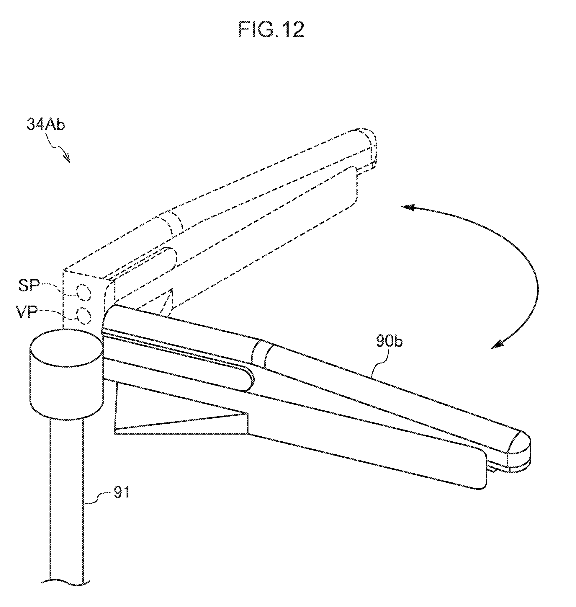
D00013

D00014
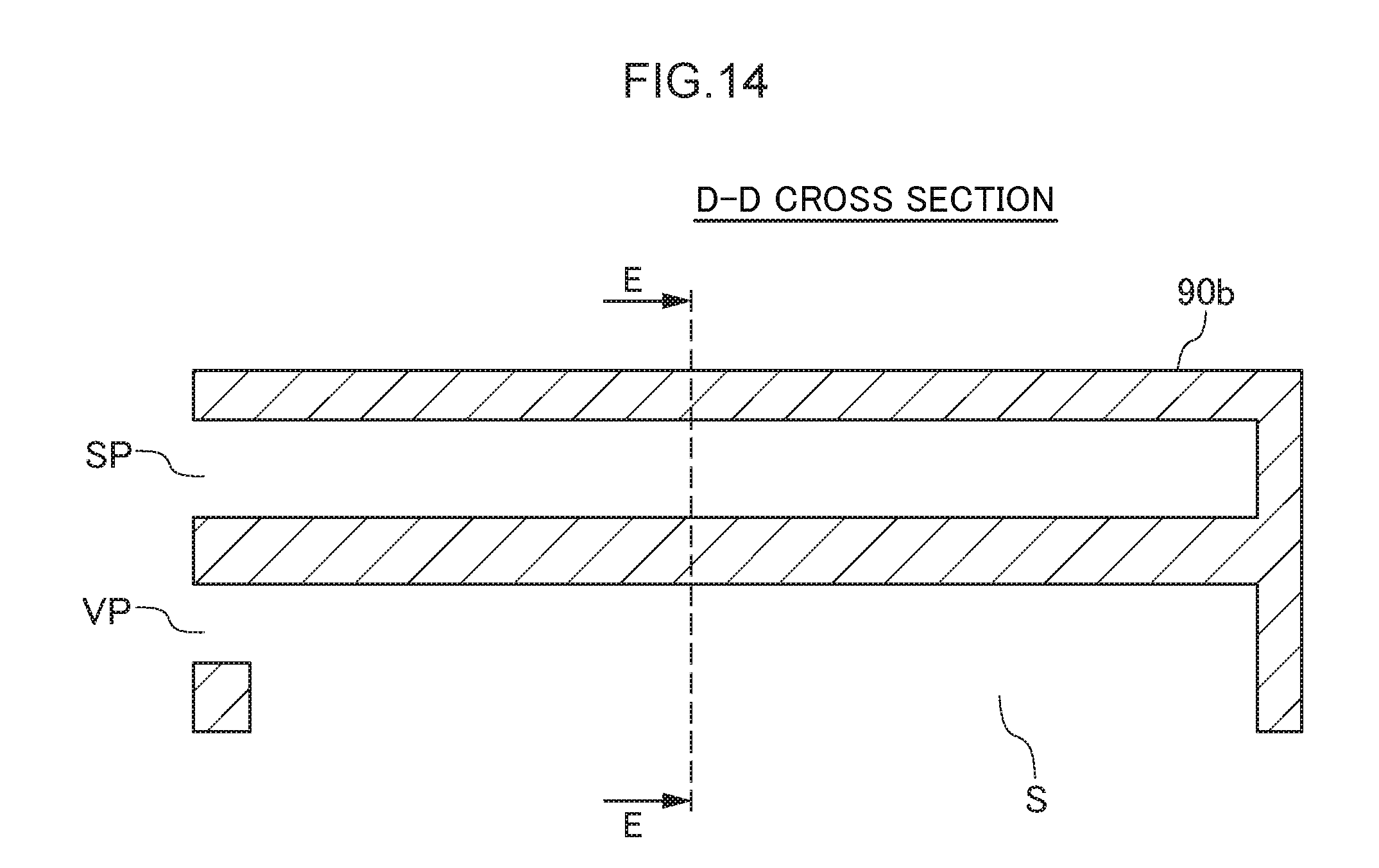
D00015

D00016

D00017
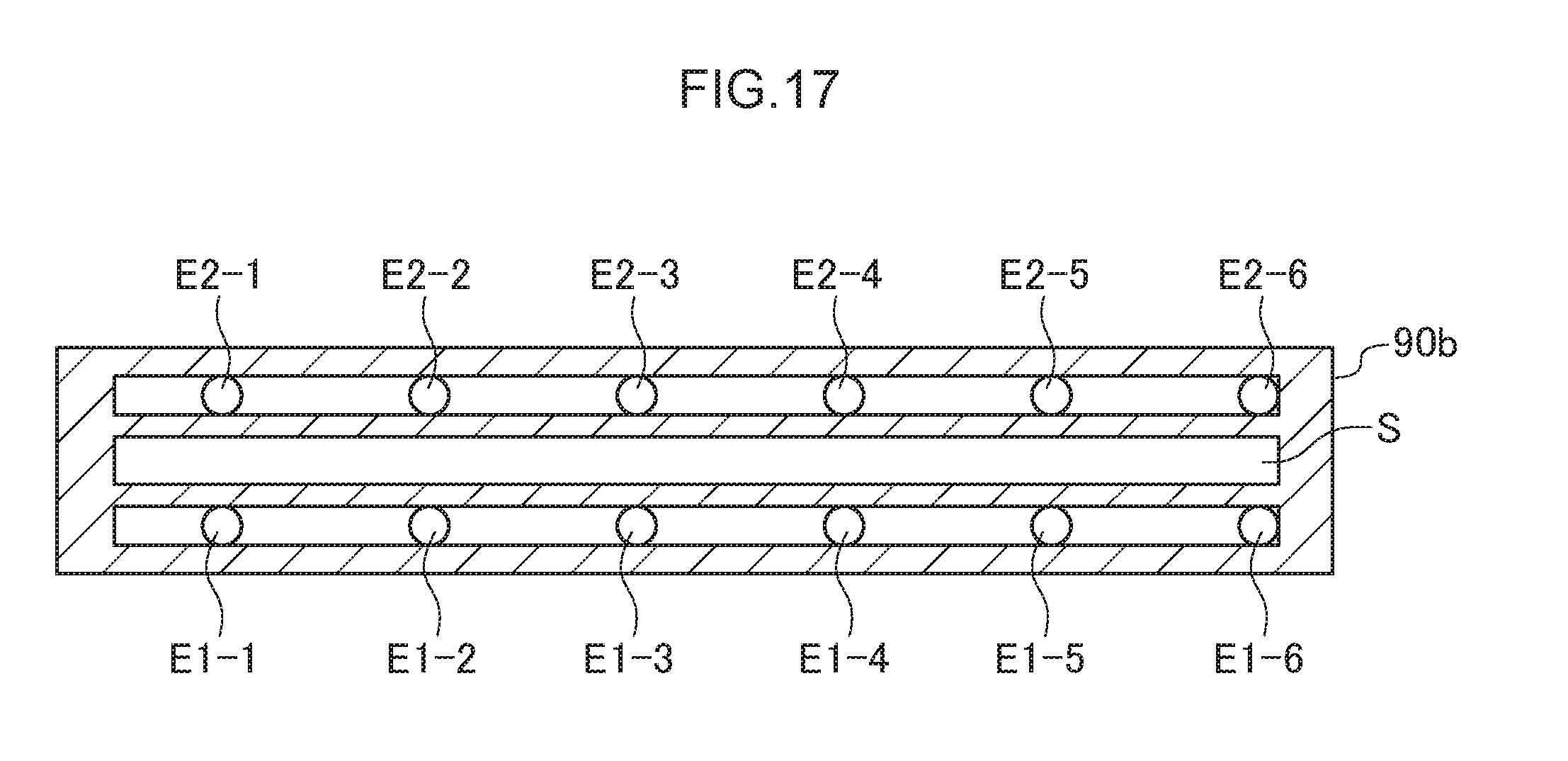
D00018
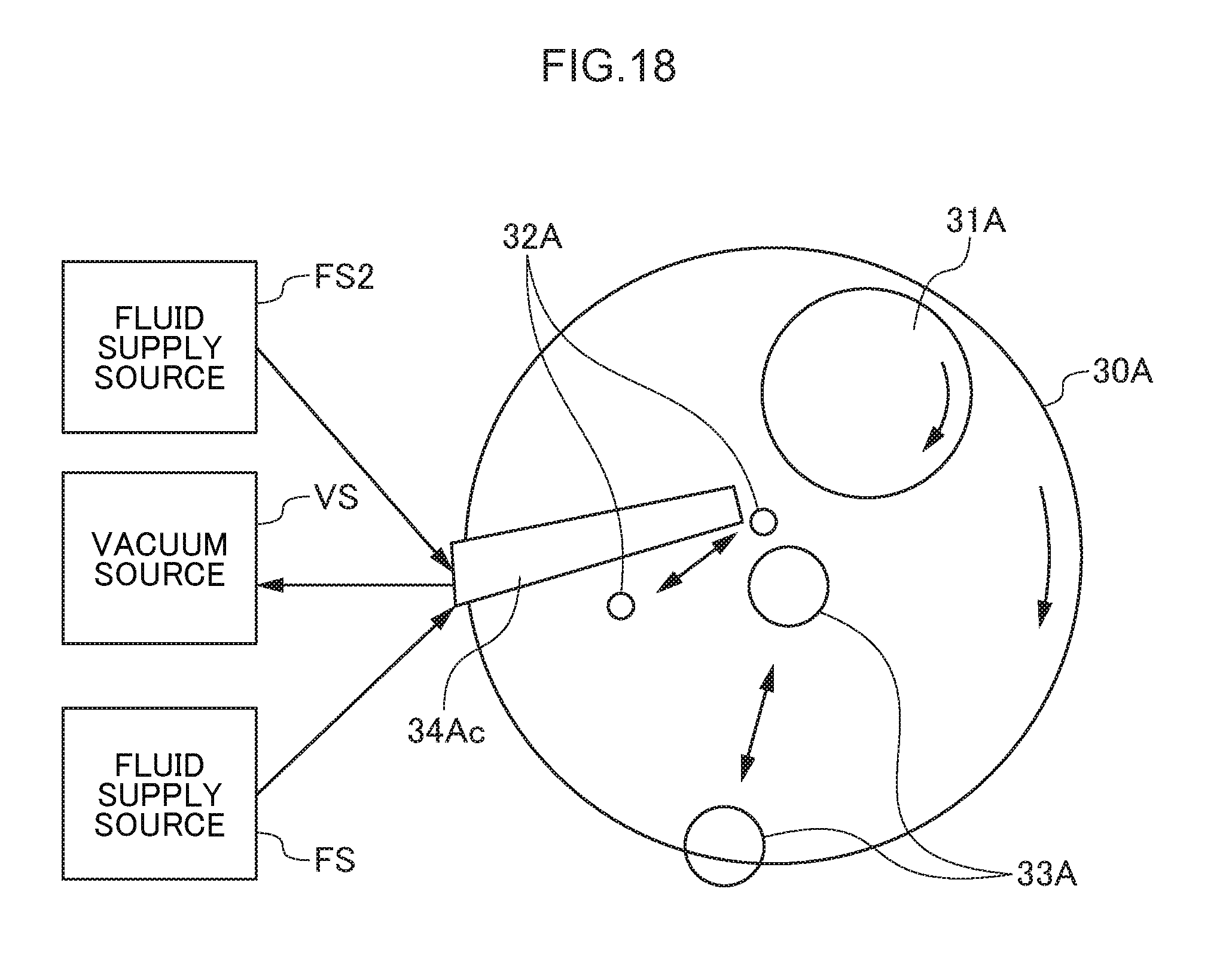
D00019
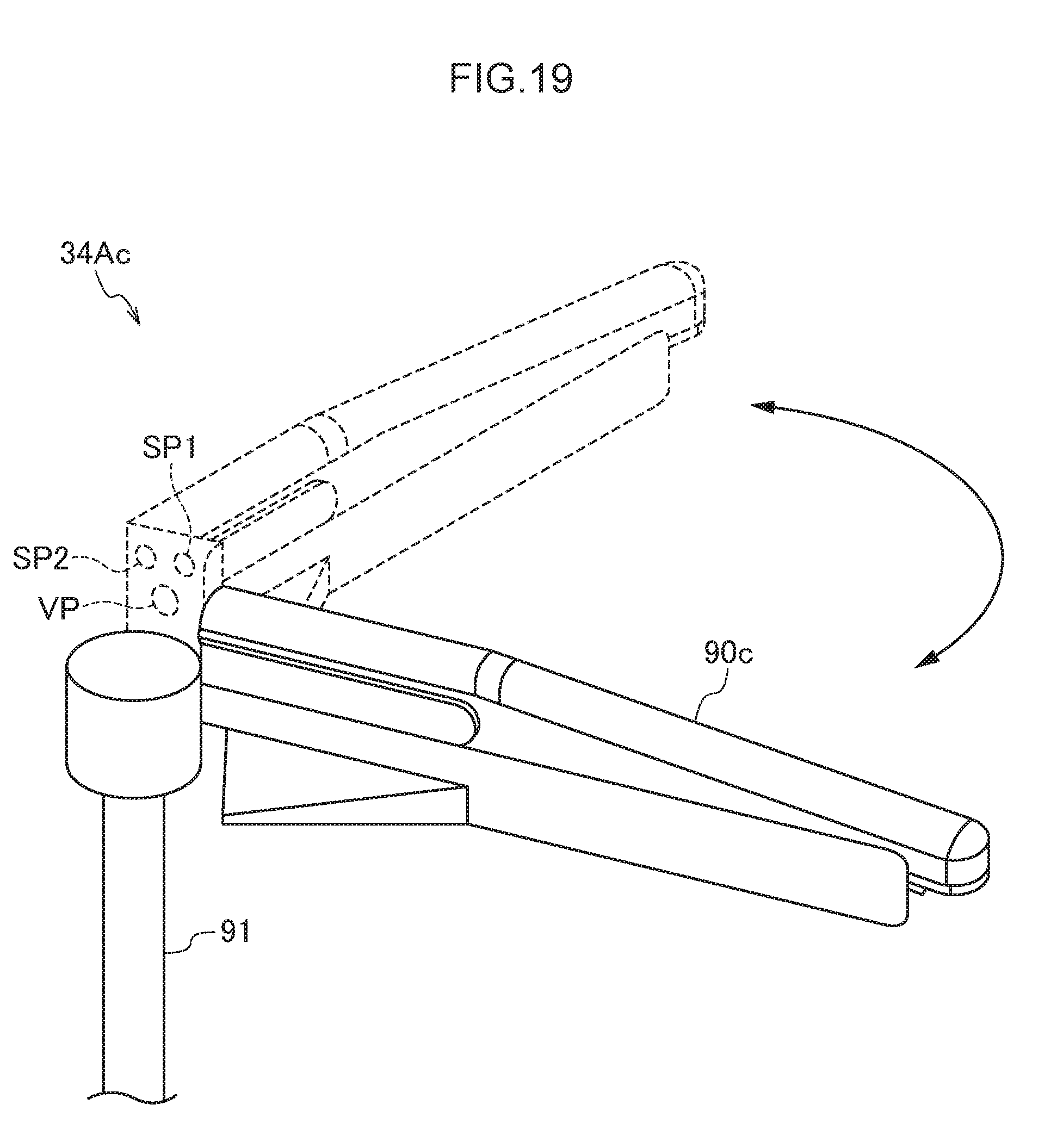
D00020

D00021

D00022

D00023
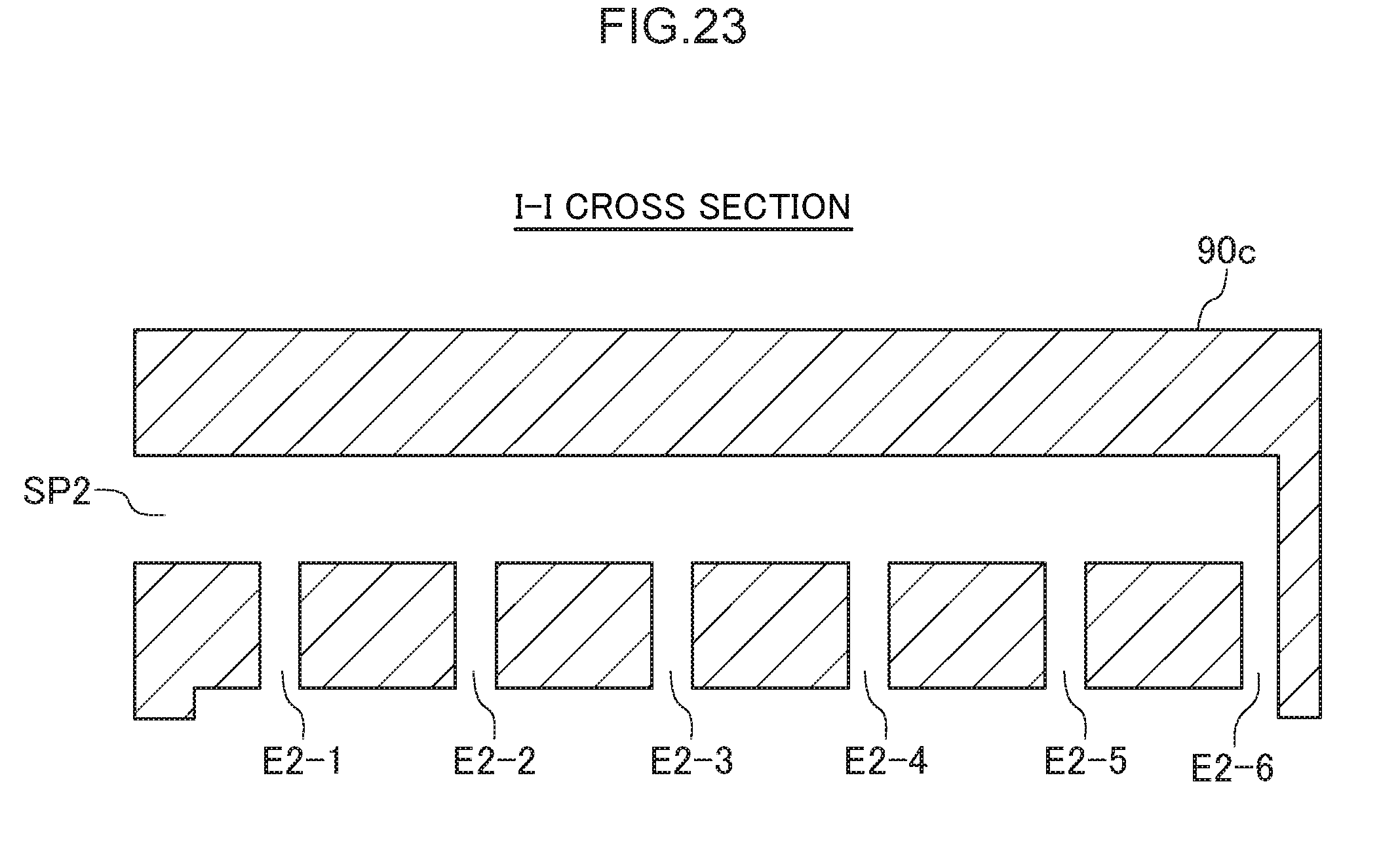
D00024

D00025

D00026

D00027
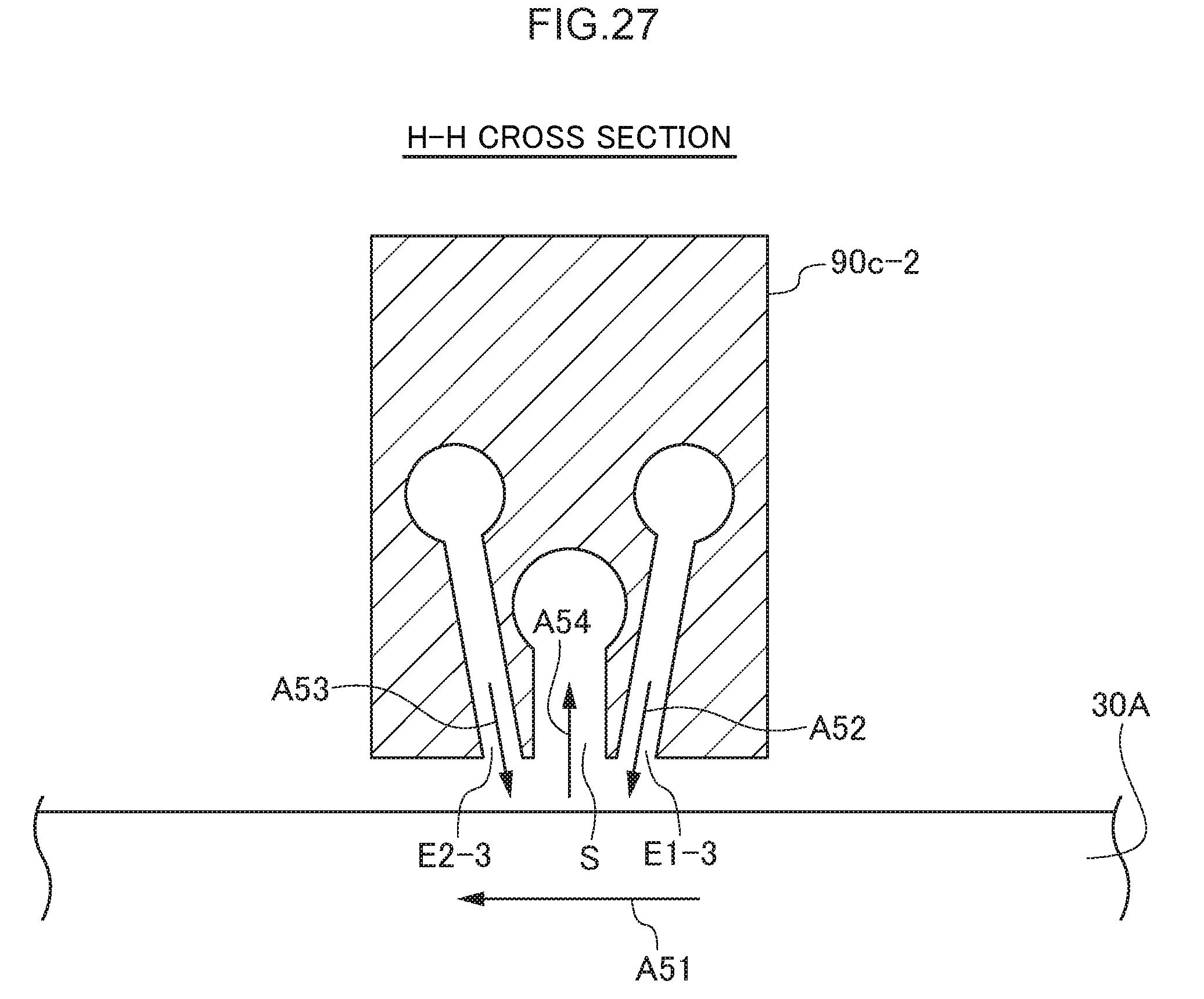
D00028

D00029
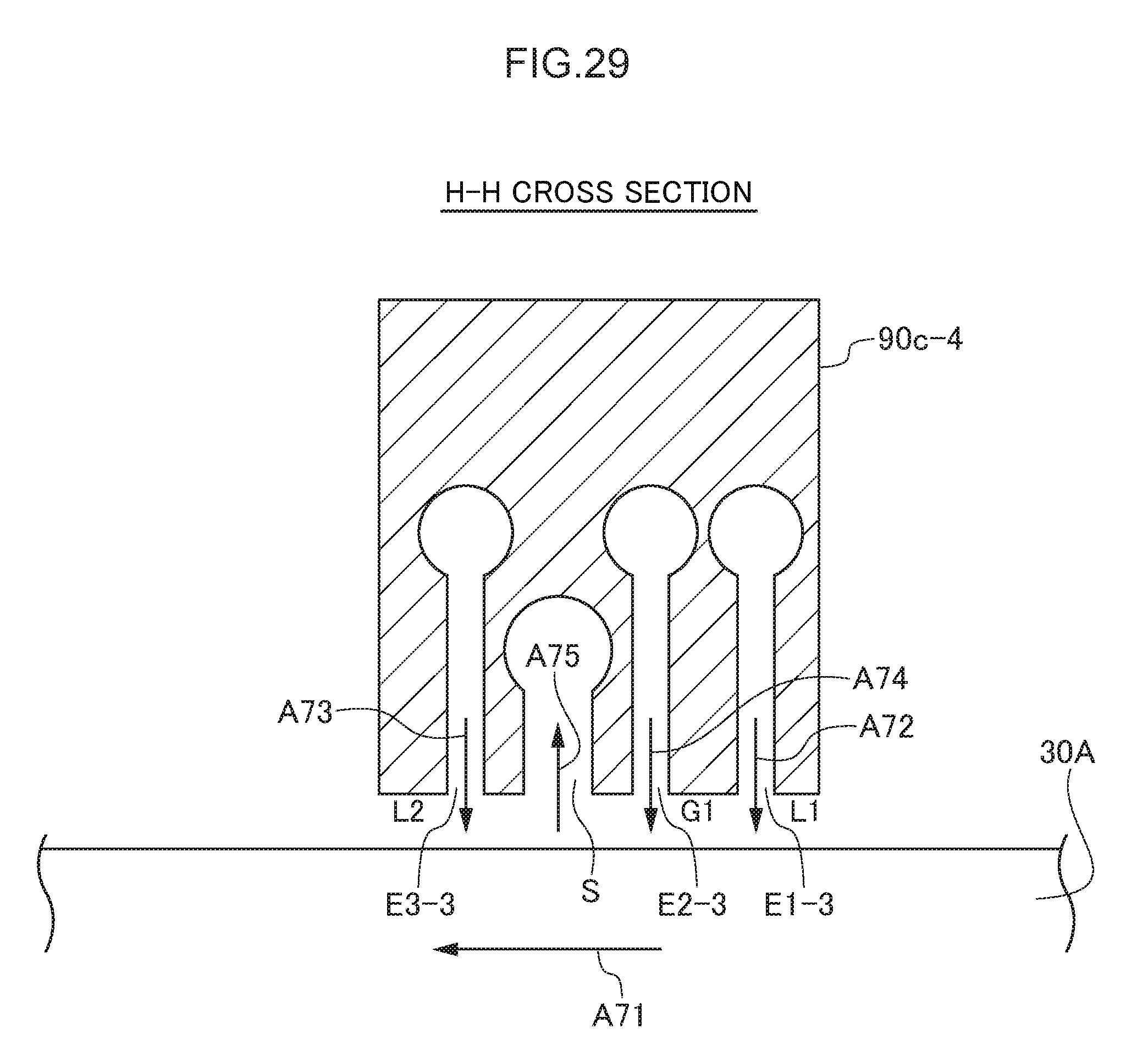
D00030
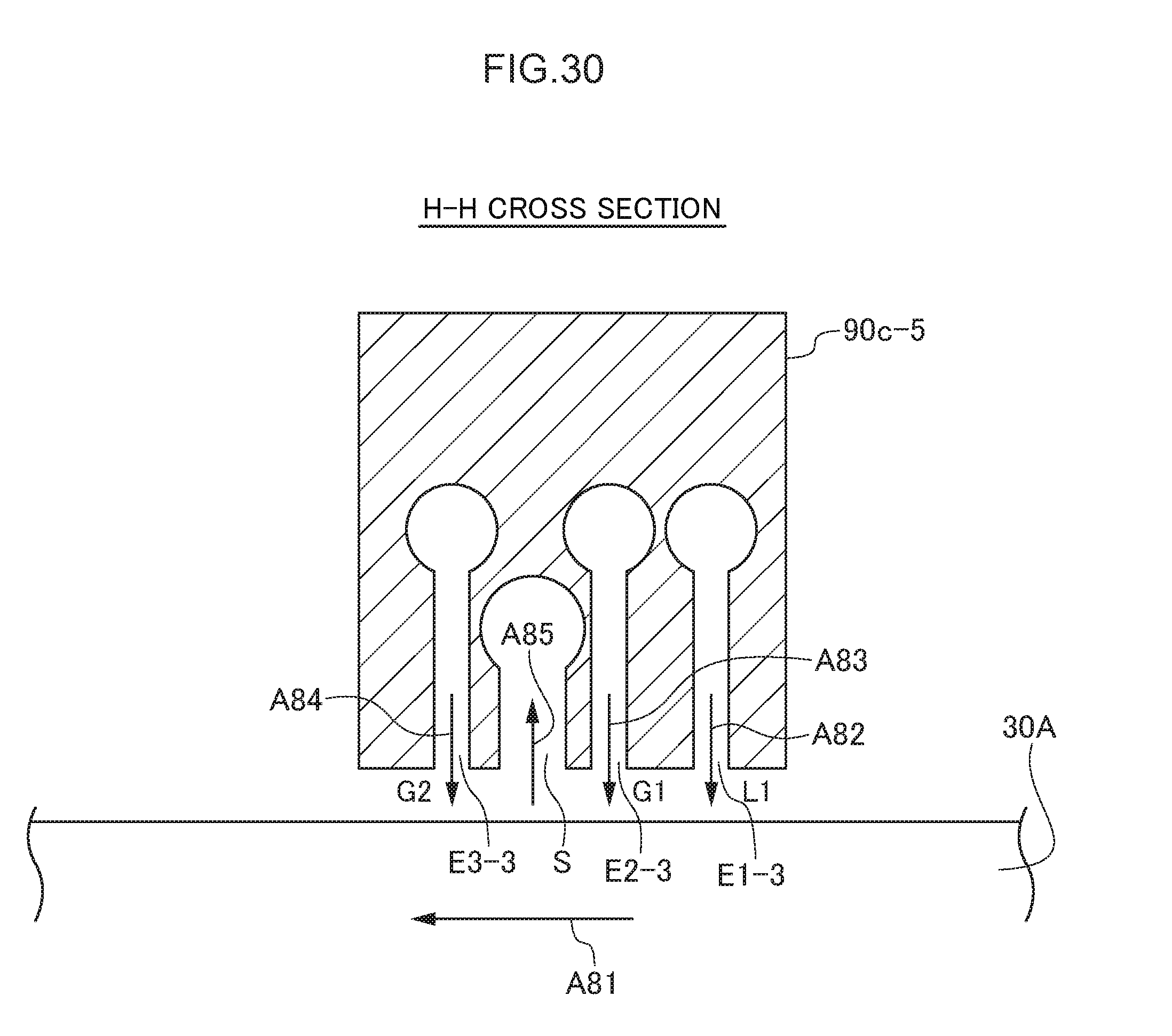
D00031
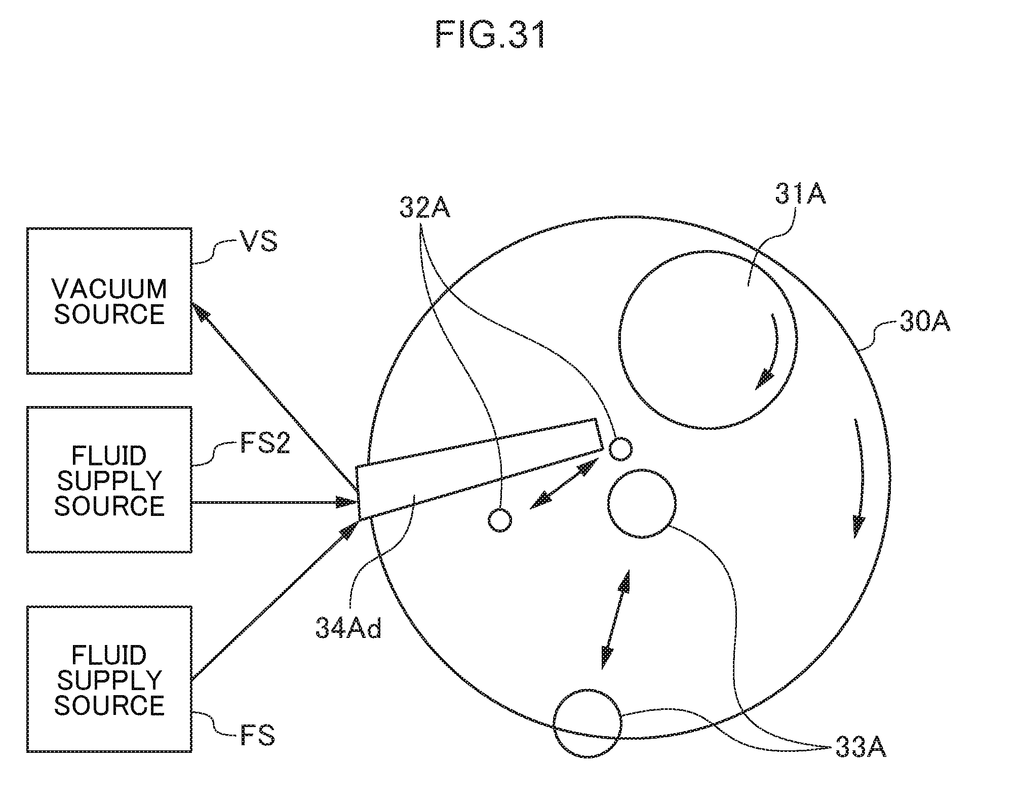
D00032
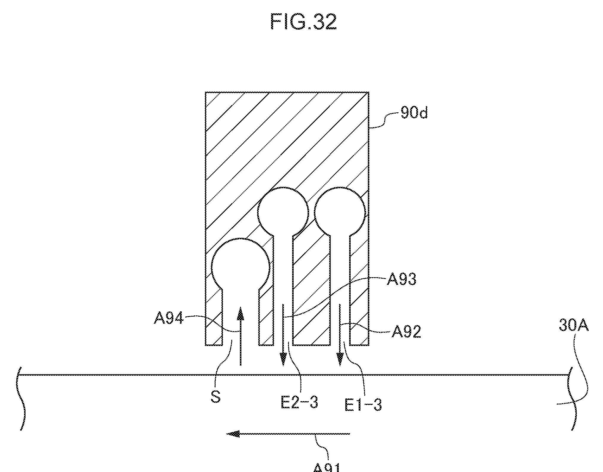
D00033
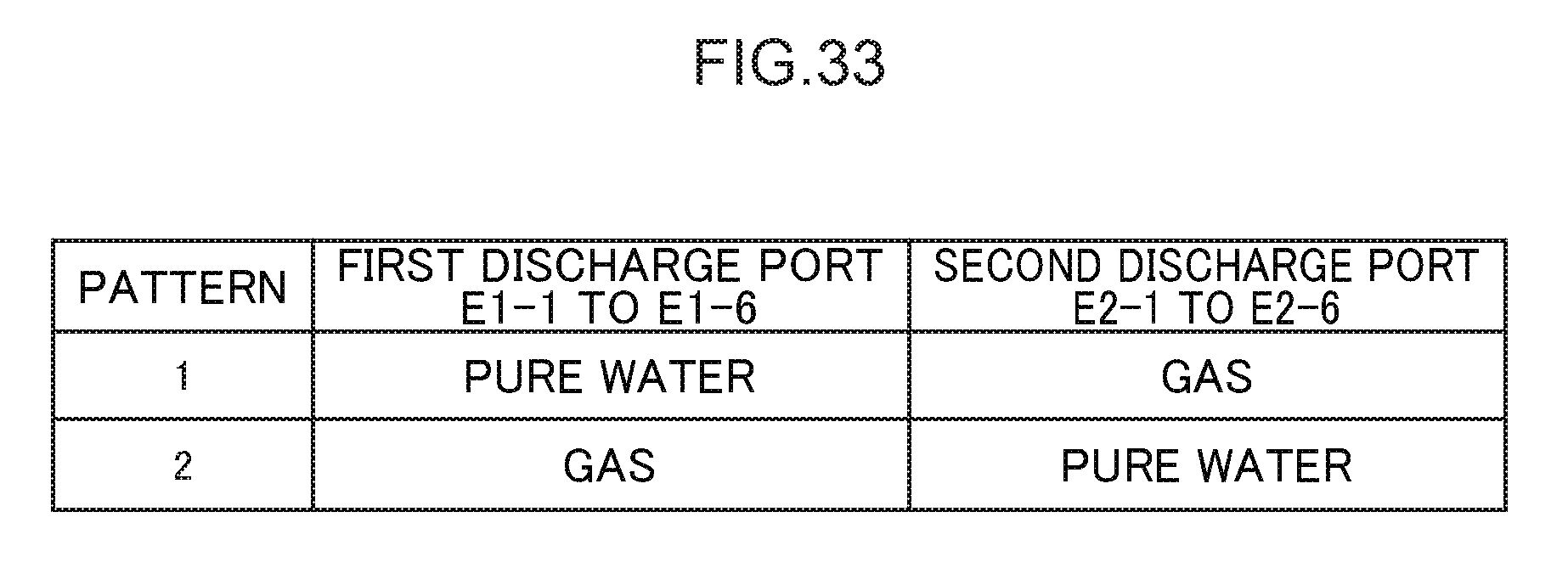
D00034

D00035

D00036

D00037

D00038

D00039

D00040

XML
uspto.report is an independent third-party trademark research tool that is not affiliated, endorsed, or sponsored by the United States Patent and Trademark Office (USPTO) or any other governmental organization. The information provided by uspto.report is based on publicly available data at the time of writing and is intended for informational purposes only.
While we strive to provide accurate and up-to-date information, we do not guarantee the accuracy, completeness, reliability, or suitability of the information displayed on this site. The use of this site is at your own risk. Any reliance you place on such information is therefore strictly at your own risk.
All official trademark data, including owner information, should be verified by visiting the official USPTO website at www.uspto.gov. This site is not intended to replace professional legal advice and should not be used as a substitute for consulting with a legal professional who is knowledgeable about trademark law.