Apparatus For Dispensing A Vapor Phase Reactant To A Reaction Chamber And Related Methods
Jdira; Lucian ; et al.
U.S. patent application number 16/130798 was filed with the patent office on 2019-03-28 for apparatus for dispensing a vapor phase reactant to a reaction chamber and related methods. The applicant listed for this patent is ASM IP Holding B.V.. Invention is credited to Lucian Jdira, Yoshio Susa, Herbert Terhorst, Naoto Tsuji.
| Application Number | 20190093221 16/130798 |
| Document ID | / |
| Family ID | 65807275 |
| Filed Date | 2019-03-28 |


| United States Patent Application | 20190093221 |
| Kind Code | A1 |
| Jdira; Lucian ; et al. | March 28, 2019 |
APPARATUS FOR DISPENSING A VAPOR PHASE REACTANT TO A REACTION CHAMBER AND RELATED METHODS
Abstract
An apparatus for dispensing a vapor phase reactant to a reaction chamber is disclosed. The apparatus may include: a first chamber configured for holding a source chemical with a first fill level; and a second chamber configured for holding the source chemical with a second fill level and in fluid communication with the first chamber via a fluid channel below the first and second fill levels. The apparatus may also include: a second chamber inlet opening in fluid communication with a pressurizing gas feed provided with a flow controller configured for controlling a flow of a pressurizing gas in the second chamber to control the first fill level in the first chamber. Methods for dispensing a vapor phase reactant are also provided.
| Inventors: | Jdira; Lucian; (Nieuw Vennep, NL) ; Terhorst; Herbert; (Amersfoort, NL) ; Tsuji; Naoto; (Tokyo, JP) ; Susa; Yoshio; (Tokyo, JP) | ||||||||||
| Applicant: |
|
||||||||||
|---|---|---|---|---|---|---|---|---|---|---|---|
| Family ID: | 65807275 | ||||||||||
| Appl. No.: | 16/130798 | ||||||||||
| Filed: | September 13, 2018 |
Related U.S. Patent Documents
| Application Number | Filing Date | Patent Number | ||
|---|---|---|---|---|
| 62562112 | Sep 22, 2017 | |||
| Current U.S. Class: | 1/1 |
| Current CPC Class: | C23C 16/45557 20130101; C23C 16/4481 20130101; H01L 21/67017 20130101; C23C 16/45561 20130101 |
| International Class: | C23C 16/448 20060101 C23C016/448; C23C 16/455 20060101 C23C016/455 |
Claims
1. An apparatus for dispensing a vapor phase reactant to a reaction chamber, the apparatus comprising: a first chamber configured for holding a source chemical with a first fill level; a second chamber configured for holding the source chemical with a second fill level and in fluid communication with the first chamber via a fluid channel below the first and second fill levels; a first chamber inlet opening in fluid communication with a carrier gas feed line configured for flowing a carrier gas into the first chamber to cause a vapor of the source chemical to become entrained in the carrier gas to produce the vapor phase reactant; a first chamber outlet opening in fluid communication with a gas outlet line and configured for dispensing the vapor phase reactant from the first chamber; and a second chamber inlet opening in fluid communication with a pressurizing gas feed line provided with a flow controller configured for controlling a flow of a pressurizing gas in the second chamber to control the first fill level in the first chamber.
2. The apparatus of claim 1, wherein the carrier gas feed line is configured for flowing a carrier into the first chamber above the first fill level.
3. The apparatus of claim 1, further comprising a second chamber outlet opening in fluid communication with a gas outlet line configured to release at least a portion of the pressuring gas from the second chamber.
4. The apparatus of claim 1, further comprising a control unit operably connected to the flow controller of the pressurizing gas feed line to control the flow of the pressurizing gas.
5. The apparatus of claim 4, further comprising a liquid level sensor operably connected with the control unit for measuring the first fill level in the first chamber and the control unit is programmed to control the flow of the pressurizing gas into the second chamber via the flow controller on the basis of the measured first fill level to regulate the first fill level to a substantially constant level.
6. The apparatus of claim 1, further comprising an additional liquid level sensor disposed within the second chamber and contacting the source chemical.
7. The apparatus of claim 1, further comprising an additional second chamber inlet opening in fluid communication with a vapor feed line configured for flowing additional source chemical into the second chamber.
8. The apparatus of claim 1, wherein the first chamber comprises an inner cylinder and the second chamber comprises an outer partially hollow cylinder disposed concentric with and surrounding the inner cylinder.
9. The apparatus of claim 8, further comprising a heating apparatus disposed between the inner cylinder and the outer cylinder.
10. The apparatus of claim 1, further comprising a heating apparatus disposed around the first chamber.
11. The apparatus of claim 1, further comprising a heating apparatus disposed around the second chamber.
12. The apparatus of claim 1, wherein a total volume of source chemical held within the first chamber and the second chamber is greater than 4 liters.
13. The apparatus of claim 1, wherein the temperature gradient across a total volume of the source chemical is less than 1.degree. C.
14. A method for dispensing a vapor phase reactant to a reaction chamber, the method comprising: providing a first chamber for holding a source chemical with a first fill level; providing a second chamber configured for holding the source chemical with a second fill level in fluid communication with the first chamber via a fluid channel below the first and second fill level; flowing a carrier gas into the first chamber through a first chamber inlet opening, wherein flowing the carrier gas into the first chamber causes a vapor of the source chemical to become entrained in the carrier gas to produce the vapor phase reactant; dispensing the vapor phase reactant from the first chamber via a first chamber outlet opening in fluid communication with an outlet gas line; and controlling the flow of a pressurizing gas into the second chamber via a second chamber inlet opening to regulate the first fill level to a substantially constant level.
15. The method of claim 14, further comprising releasing at least a portion of the pressurizing gas from the second chamber via a second chamber outlet opening.
16. The method of claim 14, wherein controlling the flow of a pressurizing gas into the second chamber further comprises controlling the pressure over the source chemical in the second chamber utilizing a pressure control unit.
17. The method of claim 14, wherein regulating the first fill level at a substantially constant level further comprises monitoring the first fill level in the first chamber utilizing a liquid level sensor.
18. The method of claim 14, further comprising monitoring the second fill level in the second chamber utilizing an additional liquid level sensor.
19. The method of claim 14, wherein maintaining the first fill level at a substantially constant level further comprises supplying additional source chemical to either the first chamber or the second chamber.
20. The method of claim 14, wherein the first chamber comprises an inner cylinder and the second chamber comprises an outer partially hollow cylinder disposed concentric with and surrounding the inner cylinder, wherein a channel is disposed between the inner cylinder and the outer cylinder.
21. The method of claim 20, further comprising providing a heating apparatus within the channel disposed between the inner cylinder and the outer cylinder.
22. The method of claim 20, further comprising providing a heating apparatus around the outer surface of the outer cylinder.
23. The method of claim 14, further comprising heating the source chemical to a temperature of greater than approximately 80.degree. C. with a temperature gradient of less than 1.degree. C.
24. A method for dispensing a vapor phase reactant to a reaction chamber, the method comprising: providing a first chamber and second chamber, wherein the first chamber and the second chamber are in fluid communication with one another; filling the first chamber with a source chemical up to a first fill level; filling the second chamber with the source chemical up to a second fill level; consuming a portion of the source chemical held within the first chamber; and increasing the pressure over the second fill level of the source chemical held within the second chamber to substantially preserve the first fill level in the first chamber.
Description
CROSS-REFERENCE TO RELATED APPLICATION
[0001] This application claims the benefit of U.S. Provisional Application No. 62/562,112, entitled "Apparatus for Dispensing a Vapor Phase Reactant to a Reaction Chamber and Related Methods" and filed on Sep. 22, 2017, the disclosure of which is hereby incorporated herein for reference.
FIELD OF INVENTION
[0002] The present disclosure relates generally to an apparatus for dispensing a vapor phase reactant to a reaction chamber and particular an apparatus for dispensing a highly stable flow of vapor phase reactant to a reaction chamber for an extended period of time. The disclosure also includes methods for dispensing a vapor phase reactant to a reaction chamber.
BACKGROUND OF THE DISCLOSURE
[0003] Semiconductor processing apparatus commonly use one or more vapor phase reactants, i.e., precursors, as source chemicals for performing semiconductor substrate processes, such as, for example, deposition processes, cleaning processes and etching processes. The vapor phase reactants are generally stored in chemical bottles, also commonly referred to as chemical ampoules.
[0004] High volume semiconductor fabrication facilities may utilize a large volume of vapor phase reactants resulting in the requirement to either regularly re-charge the chemical ampoules with additional precursor, or alternatively, frequently exchange the discharged chemical ampoules for full chemical ampoules.
[0005] However, there are some forms of precursors which are not readily adaptable for re-charge of the chemical ampoule, for example, a particular precursor may be easily degraded or a particular precursor may become strongly attached to the inner surface of the chemical ampoule during the re-charge procedure. In addition, the exchange of the discharged chemical ampoule for a full chemical ampoule may incur undesirable down time for the semiconductor processing apparatus and may also necessitate the need for safe storage of a large number of chemical ampoules. Therefore, there is a desire to limit the frequency of chemical ampoule exchanges or chemical ampoule re-charges.
[0006] One fundamental method for reducing the frequency of chemical ampoule exchange or chemical ampoule re-charge is to increase the size of the chemical ampoule thereby allowing the chemical ampoule to store more source chemical. However, chemical ampoules are commonly heated to bring the source chemical up to an operational temperature and stable, repeatable semiconductor processing performance necessitates the temperature gradient across the precursor stored in the chemical ampoule be minimized. For example, a chemical ampoule may be heated by a form of heater referred to as a belt heater, wherein the belt heater is wrapped around and encloses the outer surface of the chemical ampoule. However, as the size of the chemical ampoule increases an increased proportion of the heat provided by the belt heater may be undesirably absorbed at the outer surface of the chemical ampoule, thereby producing an undesirable thermal gradient across the chemical ampoule and consequential a deterioration in semiconductor fabrication processes.
[0007] In addition to the problems associated with heating a larger chemical ampoule, chemical ampoule upsizing may result in additional processing issues. For example, deposition processes, such as, for example, atomic layer deposition processes, may utilize one or more chemical ampoules as the chemical source(s) for deposition of materials. It may be necessary to perform a stabilization process, prior to running product substrates, in order to stabilize the vapor pressure of the precursor inside the chemical ampoule. This stabilization process may expend valuable processing time and may be referred to as "dummy time." It has been found that as the volume of the chemical ampoule increases, the "dummy time" required to stabilize the vapor pressure of the precursor inside the chemical ampoule also noticeably increases, thereby wasting costly processing time as well as consuming valuable precursor.
[0008] A chemical ampoule may be connected to a source of one or more carrier gases. The carrier gases are introduced into the chemical ampoule and drawn over the exposed surface of the source chemical, i.e., the precursor, held within the chemical ampoule. The resulting evaporation of the source chemical causes a vapor of the source chemical to become entrained in the carrier gas to thereby produce the vapor phase reactant which can be dispensed to a reaction chamber. It has been found that the maximum evaporation rate of the source chemical occurs directly below the carrier gas inlet, i.e., where the carrier gas flow is most proximate to the source chemical. It has also been found that as the source chemical is consumed the fill level of the source chemical reduces, increasing the distance between the carrier gas inlet and the exposed surface of the source chemical. The increase in distance between the carrier gas inlet and the exposed surface of the source chemical can result in an unwanted variation in the vapor phase reactant flow out from the chemical ampoule to the reaction chamber. For example, as the source chemical is consumed and the distance between the carrier gas inlet and the surface of the source chemical increases, the flow of vapor phase reactant from the chemical ampoule to the reaction chamber may decrease, resulting in an undesirable variation in semiconductor processing conditions.
[0009] Accordingly, apparatus and methods are desirable for dispensing a highly stable flow of vapor phase reactant to a reaction chamber for an extended period of time from a high volume chemical ampoule.
SUMMARY OF THE DISCLOSURE
[0010] This summary is provided to introduce a selection of concepts in a simplified form. These concepts are described in further detail in the detailed description of example embodiments of the disclosure below. This summary is not intended to identify key features or essential features of the claimed subject matter, nor is it intended to be used to limit the scope of the claimed subject matter.
[0011] In some embodiments of the disclosure, an apparatus for dispensing a vapor phase reactant to a reaction chamber is provided. The apparatus may comprise: a first chamber configured for holding a source chemical with a first fill level; and a second chamber, configured for holding a source chemical with a second fill level in fluid communication with the first chamber via a fluid channel below the first and second fill levels. The apparatus may also comprise; a first chamber inlet opening in fluid communication with a carrier gas feed line configured for flowing a carrier gas into the first chamber to cause a vapor of the source chemical to become entrained in the carrier gas to produce the vapor phase reactant. The apparatus may further comprise: a first chamber outlet opening in fluid communication with a gas outlet line and configured for dispensing the vapor phase reactant from the first chamber; and a second chamber inlet opening in fluid communication with a pressurizing gas feed line provided with a flow controller configured for controlling a flow of a pressurizing gas in the second chamber to control the first fill level in the first chamber.
[0012] The embodiments of the disclosure may also provide methods for dispensing a vapor phase reactant to a reaction chamber. The methods may include: providing a first chamber for holding a source chemical with a first fill level, and providing a second chamber configured for holding the source chemical with a second fill level in fluid communication with the first chamber via a fluid channel. The methods may also comprise: flowing a carrier gas into the first chamber through a first chamber inlet opening, wherein flowing the carrier gas into the first chamber causes a vapor of the source chemical to become entrained in the carrier gas to produce the vapor phase reactant, and dispensing the vapor phase reactant from the first chamber via a first chamber outlet opening in fluid communication with an outlet gas line. The methods may further comprise: controlling the flow of a pressurizing gas into the second chamber via a second chamber inlet opening to regulate the first fill level to a substantially constant level.
BRIEF DESCRIPTION OF THE DRAWING FIGURES
[0013] While the specification concludes with claims particularly pointing out and distinctly claiming what are regarded as embodiments of the invention, the advantages of embodiments of the disclosure may be more readily ascertained from the description of certain examples of the embodiments of the disclosure when read in conjunction with the accompanying drawings, in which:
[0014] FIG. 1 is a schematic diagram of a chemical delivery apparatus for dispensing a vapor phase reactant to a reaction chamber according to the embodiments of the disclosure;
[0015] FIG. 2A is a three-dimensional schematic diagram of an alternative chemical delivery apparatus for dispensing a vapor phase reactant to a reaction chamber according to the embodiments of the disclosure;
[0016] FIG. 2B is a cross-sectional schematic diagram of the alternative chemical delivery apparatus for dispensing a vapor phase reactant to a reaction chamber according to the embodiments of the disclosure;
[0017] FIG. 3 is an exploded view of a temperature controlled chemical dispensing apparatus according to the embodiments of the disclosure;
[0018] FIG. 4 illustrates an exemplary process flow for dispensing a vapor phase reactant to a reaction chamber according to the embodiments of the disclosure.
DETAILED DESCRIPTION OF EXEMPLARY EMBODIMENTS
[0019] Although certain embodiments and examples are disclosed below, it will be understood by those in the art that the invention extends beyond the specifically disclosed embodiments and/or uses of the invention and obvious modifications and equivalents thereof. Thus, it is intended that the scope of the invention disclosed should not be limited by the particular disclosed embodiments described below.
[0020] The illustrations presented herein are not meant to be actual views of any particular material, structure, or device, but are merely idealized representations that are used to describe embodiments of the disclosure.
[0021] The embodiments of the disclosure may include apparatus and methods for dispensing a vapor phase reactant to a reaction chamber. In particular, the embodiments of the disclosure may include an apparatus capable of dispensing a highly stable flow of vapor phase reactant to a semiconductor reaction chamber for an extended period of time.
[0022] The problems associated with the temperature gradient, i.e., the temperature differential, across the volume of the source chemical held within the dispensing apparatus may be alleviated by the employment of two or more independently controlled heating apparatus integrated into the chemical dispensing apparatus. For example, the two or more independently controlled heating apparatus may be disposed at strategic locations in the chemical dispensing apparatus. The two or more independently controlled heating apparatus therefore minimize the temperature gradient across the volume of the source chemical and thereby provide a uniform form of vapor phase reactant to a reaction chamber.
[0023] In addition, the problems associated with undesirable precursor stabilization time and variation in vapor phase reactant flow over an extended period of time may be addressed by utilizing a two chamber chemical ampoule, wherein the two chambers are fluidly connected to one another. A pressure control unit may be associated with a pressurizing gas feed line into a second chamber such that a pressurizing gas may introduce a controlled pressure over the surface of the source chemical in the second chamber. The controlled pressure over the source chemical in the second chamber can thereby regulate the fill level in the second chamber, i.e., the level of the exposed surface of source chemical. Since the first chamber is fluidly connected to a second chamber the ability to control the fill level in a second chamber consequentially results in the ability to control, i.e., regulate, the fill level in the first chamber. The two chamber chemical dispensing apparatus can therefore substantially maintain the distance between the carrier gas inlet and the exposed surface of the source chemical, in the dispensing portion of the apparatus, resulting in a reduced stabilization time and a more stable vapor phase reactant flow over an extended period of time.
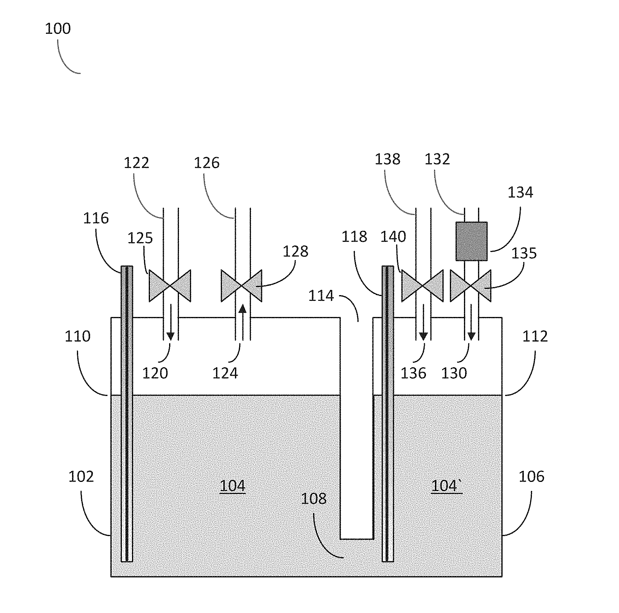
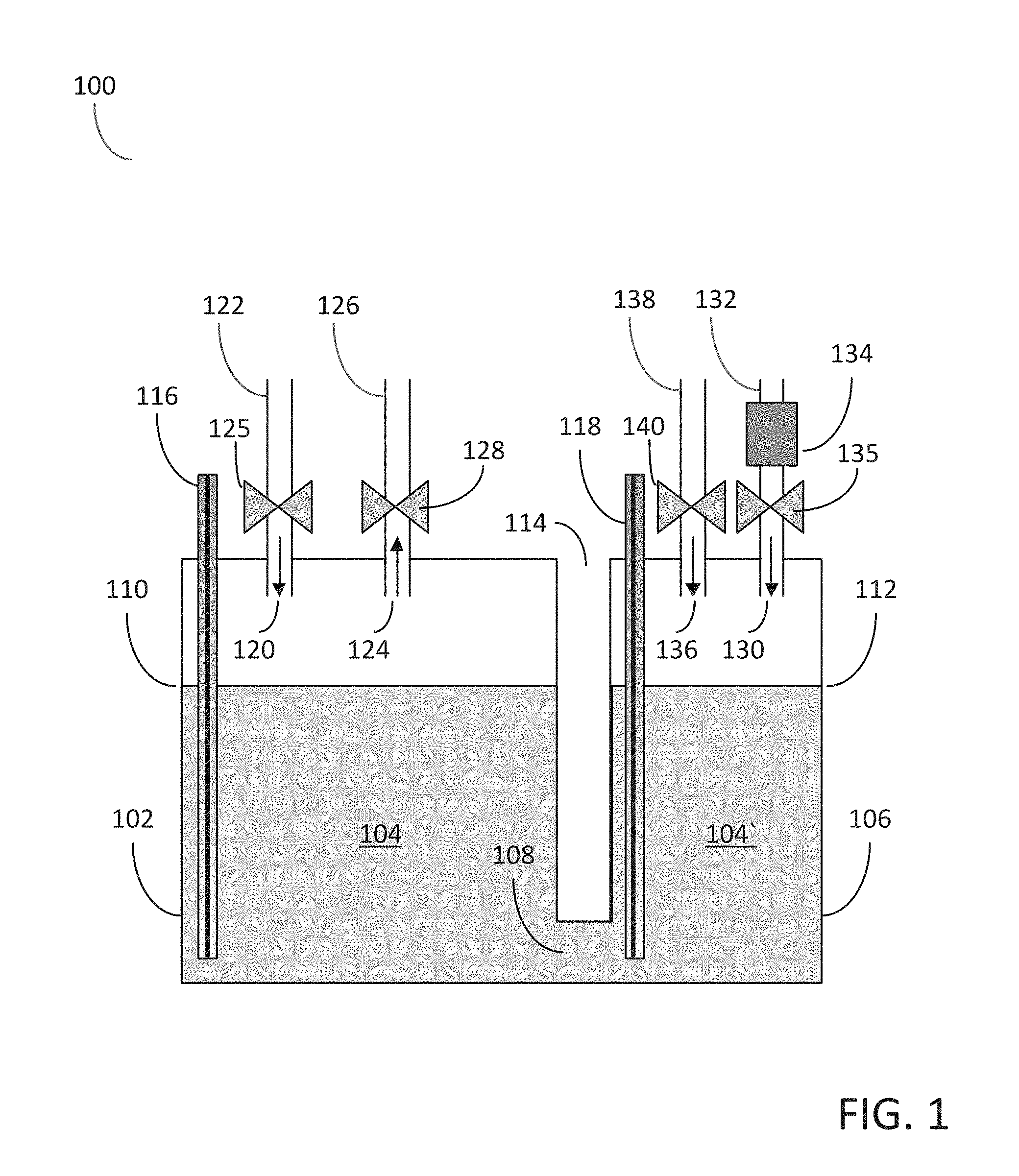
[0024] The embodiments of the disclosure may be understood in more detail with reference to FIG. 1 which illustrates a schematic diagram of a chemical delivery apparatus for dispensing a vapor phase reactant to a reaction chamber according to the embodiments of the disclosure. In more detail, the apparatus 100 for delivering a vapor phase reactant to a reaction chamber may comprise a first chamber 102 configured for holding a source chemical 104 and a second chamber 106 configured for holding a source chemical 104'. The first chamber 102 and the second chamber 106 may be fluid communication with one another as a result of a fluid channel 108 disposed between the first chamber 102 and the second chamber 106. Since the first chamber 102 and the second chamber 106 are in fluid communication with one another, the source chemical 104 and 104' disposed within the first chamber 102 and the second chamber 106 may comprise a common source chemical, i.e., the source chemical in both the first chamber 102 and the second chamber 106 are identical.
[0025] In some embodiments of the disclosure, the first chamber 102 may be partially separated from the second chamber 106 utilizing a channel 114 disposed between the two chambers, the base of the channel 114 forming the top surface of the fluid channel 108 and the common base of the first chamber 102 and the second chamber 106 forming the base of the fluid channel 108. In other embodiments, a physical barrier, such as, for example, a physical partition may be disposed partially between the first chamber 102 and the second chamber 106 whilst maintaining an unrestricted fluid channel between the two chambers.
[0026] In some embodiments of the disclosure, the source chemical 104 held within the first chamber 102 may be filled up to a first fill level 110, i.e., the first fill level 110 indicates the level of the upper exposed surface of the source chemical 104 disposed within the first chamber 102. In some embodiments of the disclosure, the source chemical 104' held within the second chamber 106 may be filled up to a second fill level 112, i.e., the second fill level 112 indicates the level of the upper exposed surface of the source chemical 104' disposed within the second chamber 106. Under equilibrium conditions, the first fill level 110 and the second fill level 112 are substantially equal, resulting from the fluid communication between the first chamber 102 and the second chamber 106, the fluid channel between the first chamber 102 and the second chamber 106 being disposed beneath the first and second fill levels.
[0027] In some embodiments of the disclosure, the first fill level 110 and the second fill level may be monitored utilizing one or more liquid level sensors. For example, a liquid level sensor 116 may be disposed within the first chamber 102 and may contact the source chemical 104 such that the position of the first fill level 110 within the first chamber 102 may be monitored. In some embodiments, the dispensing apparatus 100 may also include an additional liquid level sensor 118 disposed within the second chamber 106 and may contact the source chemical 104' such that the position of the second fill level 112 within the second chamber 106 may also be monitored.
[0028] The dispensing apparatus 100 may also comprise a first chamber inlet opening 120 in fluid communication with a carrier gas feed line 122. In addition, the carrier gas feed line 122 may include the valve 125 for controlling the flow of carrier gas into the first chamber 102. The first chamber inlet opening 120 and the carrier gas feed line 122 may be configured for a flowing a carrier gas into the first chamber 102 above the first fill level 110 to cause a vapor of the source chemical 104 to become entrained in the carrier gas to produce the vapor phase reactant.
[0029] In some embodiments of the disclosure, the dispensing apparatus 100 may also comprise a first chamber outlet opening 124 in fluid communication with a gas outlet line 126 and configured for dispensing the vapor phase reactant out from the first chamber 102. In addition, the gas outlet line 126 may include valve 128 for controlling the flow of vapor phase reactant out of the first chamber 102. The gas outlet line 126 may be fed to the reaction chamber of a semiconductor processing apparatus, such that the vapor phase reactant dispensed from the first chamber 102 may be utilized in a semiconductor fabrication process.
[0030] The dispensing apparatus 100 may also comprise a second chamber inlet opening 130 in fluid communication with a pressurizing gas feed line 132. In some embodiments of the disclosure, the pressurizing gas feed line 132 is configured for flowing a pressurizing gas above the second fill level 112, the pressurizing gas configured to substantially maintain the level of the first fill level 110 in the first chamber 102. In addition, the pressurizing gas feed line 132 may include a pressure control unit 134 disposed on the pressurizing gas feed line 132 and configured for controlling the pressure above the second fill level 112 in the second chamber 106. In addition to the pressure control unit 134, the pressurizing gas feed line 132 may further comprise the valve 135 for controlling the flow of the pressurizing gas in to the second chamber 106.
[0031] In more detail, as a carrier gas (e.g., nitrogen or argon) is fed into carrier gas feed line 122, the carrier gas flows into the volume above the first fill level 110 in the first chamber 102 and picks up vapor from the source chemical. The source chemical becomes entrained within the carrier gas to produce the vapor phase reactant which may be dispensed to a reaction chamber via gas outlet line 126. The process of flowing carrier gas, the carrier gas becoming entrained with the source chemical vapor and dispensing the vapor phase reactant out of the first chamber via gas outlet line 126, causes the volume of source chemical within the dispensing apparatus 100 to decrease and without any corrective action the level of the first fill level (and consequently the level of the second fill level) will decrease below its original position. As previously stated, as the distance between the first chamber inlet opening 120 and the first fill level 110 increases, the flow rate of the vapor phase precursor dispensed from the first chamber 102 may also vary, i.e., may decrease, resulting in undesirable process variation. In order to overcome the decrease in the level of the first fill level 110, a pressurizing gas may be feed into the second chamber 106 via pressurizing gas feed line 132. The pressurizing gas will controllably increase the pressure above the second fill level 112 in the second chamber 106, utilizing pressure control unit 134, and the increase in pressure will further decrease the second fill level 112 in the second chamber 106. Since the second chamber 106 and the first chamber 102 are in fluid communication with one another, via fluid channel 108, any pressure induced decrease in the second fill level 112 in the second chamber 106 will result in an increase in the level of the first fill level 110 in the first chamber 102. Hence any increase in the distance between the first chamber inlet 120 and the first fill level 110 can be compensated for by increasing the pressure over the source chemical in the second chamber 106.
[0032] As disclosed herein, the apparatus may include and utilize a chemical dispensing apparatus comprising two fluidly connected chambers and a pressurized gas feed line to substantially maintain the level of the first fill level in the first chamber. In addition to, or alternatively, the decrease in the level of the first fill level 110 due to the consumption of the source chemical may be counteracted by the addition of further source chemical into dispensing apparatus 100, thereby replenishing the source chemical as it is utilized and consequently maintaining the level of the first fill level 110. Therefore, in some embodiments of the disclosure, the dispensing apparatus 100 may further comprise an additional second chamber inlet opening 136 in fluid communication with a vapor feed line 138 configured for flowing additional source chemical 104' into the second chamber 106. In addition, the vapor feed line 138 may also comprise a valve 140 for controlling the flow of additional source chemical 104' into the second chamber 106.
[0033] In some embodiments of the disclosure, the additional source chemical may be feed into the first chamber 102 via an appropriate additional inlet opening into the first chamber 102 (not shown). Therefore, either one or both of the first chamber and the second chamber may be replenished with additional source chemical to maintain the level of the first fill level 110 in the first chamber 102.
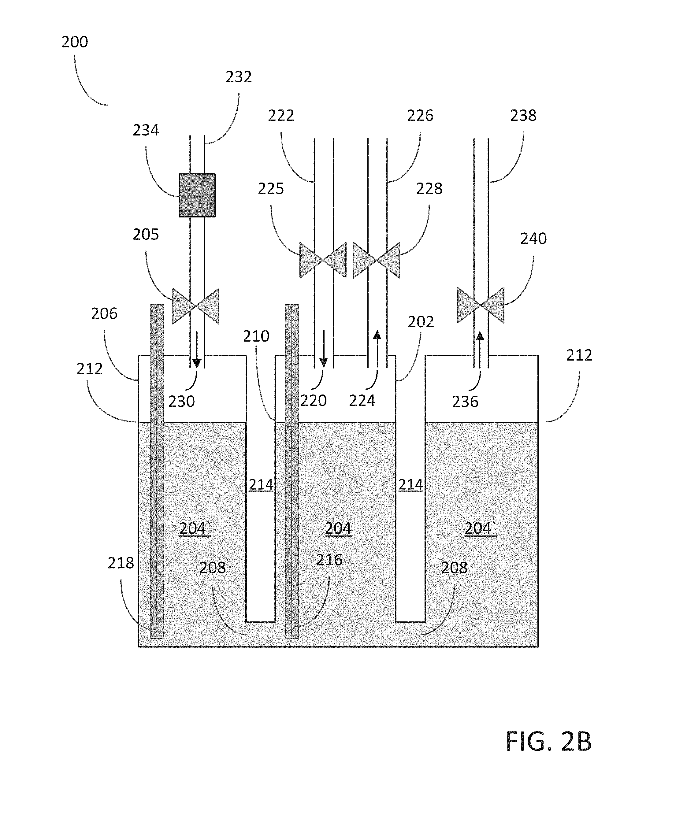
[0034] An alternative configuration of the chemical dispensing apparatus according to the embodiments of the disclosure is illustrated in FIGS. 2A and 2B, wherein FIG. 2A comprises a three-dimensional schematic diagram of a chemical delivery apparatus and FIG. 2B illustrates a cross-sectional view of the same chemical delivery apparatus through the plane denoted by the A-A plane referenced in FIG. 2A. It should be noted that the cross-sectional view illustrated in FIG. 2B represents the chemical delivery apparatus at the equilibrium position.
[0035] In more detail, the chemical dispensing apparatus 200 comprises a first chamber 202, i.e., an inner chamber, configured for holding a source chemical up to a first fill level 210. The chemical dispensing apparatus 200 also comprises a second chamber 206, i.e., an outer chamber, configured for holding a source chemical up to a second fill level 212. The first chamber 202 (inner chamber) and the second chamber 206 (outer chamber) are in fluid communication with one another via a fluid channel 208.
[0036] In some embodiments of the disclosure, the first chamber 202 further comprises a first chamber inlet opening 220 in fluid communication with a carrier gas feed line 222 configured for flowing a carrier gas into the first chamber 202 above the first fill level 210 to cause a vapor of the source chemical 204 to become entrained in the carrier gas to produce the vapor phase reactant. An additional valve 225 may be disposed on the carrier gas feed line 222 for providing further control of the flow of the carrier gas into the first chamber 202 (see FIG. 2B).
[0037] In some embodiments of the disclosure, the first chamber 202 may also comprise a first chamber outlet 224 in fluid communication with a gas outlet line 226 and configured for dispensing the vapor phase reactant out from the first chamber. Although not shown in FIGS. 2A and 2B, gas outlet line 226 may extend out and be in fluid communication with a reaction chamber of semiconductor processing apparatus, thereby allowing a vapor phase reactant to be dispensed to the reaction chamber. The gas outlet line 226 may further comprise an additional valve 228 for providing further control of the flow of the vapor phase reactant out from the first chamber 202 (see FIG. 2B).
[0038] The chemical dispensing apparatus of FIGS. 2A and 2B may also comprise a second chamber inlet opening 230 in fluid communication with a pressurizing gas feed line 234 configured for flowing a pressurizing gas above the second fill level 212, the pressurizing gas configured to substantially maintain the level of the first fill level 210 in the first chamber 202, i.e., the inner chamber of FIGS. 2A and 2B.
[0039] To further control the pressure above the second fill level 212 in the second chamber 206, the chemical dispensing apparatus 200 may include a pressure control unit 234 disposed on the pressurizing gas feed line 232, the pressure control unit 234 configured to regulate the pressure in the second chamber 206 above the second fill level 212.
[0040] In some embodiments, the second chamber 206, i.e., the outer chamber, may further comprise a second chamber outlet opening 236 in fluid communication with a gas outlet line 238 configured for releasing at least a portion of the pressurizing gas from the second chamber 204, i.e., releasing the pressurizing gas from the second chamber 206 via gas outlet line 238 may be further utilized to control the pressure within the second chamber above the second fill level. Additional control of the pressure above the second fill level 212 within the second chamber 206 may be provided by the valve 240 disposed on the gas outlet line 238 (see FIG. 2B).
[0041] To further assist in the regulation of the level of the first fill level 210 in the first chamber 202, the dispensing apparatus 200 may further comprise one or more liquid level sensors. For example, the data recorded from the one or more liquid level sensors can be utilized in a feedback circuit to enable regulation of the pressure control unit 234 disposed upon the pressurized gas feed line 232. As a non-limiting example, a liquid level sensor 216 may be disposed within the first chamber 202 and contacting the source chemical held 204 held with the first chamber 202. In additional embodiments of the disclosure, an additional liquid level sensor 218 may be disposed within the second chamber 206 and contacting the source chemical 204' held with the second chamber 206.
[0042] Although not shown in FIGS. 2A and 2B, the chemical dispensing apparatus 200 may further comprise an additional inlet opening in one or both of the first chamber 202 and the second chamber 206, wherein the additional inlet opening is in fluid communication with a vapor feed line configured for flowing additional source chemical into one or both of the first chamber 202 and the second chamber 206. The ability to re-charge the source chemical with the chemical dispensing apparatus 200 allows for further regulation of the level of the first fill level 210 within the first chamber 202.
[0043] In some embodiments of the disclosure, the first chamber 202 may comprise an inner cylinder. In some embodiments, the inner cylinder comprise a top wall, wherein the top wall comprises a number of openings 220 and 224 configured for the inlet and outlet of gases and a further opening configured for the insertion of the liquid level sensor 216. In some embodiments, the inner cylinder further comprises a sidewall and an open base region, the open base region allowing fluid communication with the second chamber 206 via fluid channel 208.
[0044] In some embodiments of the disclosure, the second chamber 206 may comprise an outer partially hollow cylinder disposed concentric with and surrounding the inner cylinder (see FIG. 2A). The second chamber 206, i.e., the outer cylinder, may be only partially hollow as a portion of the base region of the second chamber comprises the base of the fluid channel 208 between the first chamber 202 and the second chamber 206.
[0045] In further embodiments of the disclosure, the chemical dispensing apparatus 200 comprises a channel 214 disposed between the inner cylinder (the first chamber 202) and the outer cylinder (the second chamber 204). The channel 214 may be circular in form and concentric to the inner cylinder, although other configurations may be utilized. The channel 214 may extend from the top wall of the first chamber 204 down and adjacent to the side wall of the inner cylinder, terminating prior to the base of the apparatus, the base of the channel 214 comprising a portion of the top wall of the fluid channel 208 between the first chamber 202 and the second chamber 206.
[0046] Embodiments of the disclosure may also comprise apparatus for heating a chemical dispensing apparatus and particular apparatus for minimizing the temperature gradient, i.e., the thermal differentiation, across the volume of the source chemical held within the dispensing apparatus. The embodiments of the disclosure may comprise apparatus for heating the chemical dispensing apparatus 200 of FIGS. 2A and 2B, although the apparatus described herein may be utilized to uniformly heating alternative chemical dispensing apparatus.
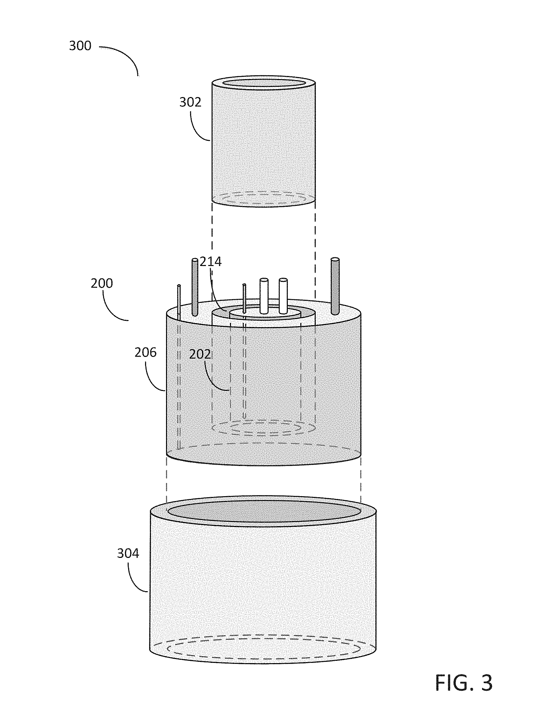
[0047] In more detail and with reference to FIG. 3, a temperature controlled chemical dispensing apparatus 300 may comprise a first heating apparatus 302, a second heating apparatus 304 and a chemical dispensing apparatus 200. As described previously herein, the chemical dispensing apparatus 200 may comprise a first chamber 202, i.e., the inner cylinder, and a second chamber 206, i.e., the outer cylinder. Disposed between the first chamber 202 and the second chamber 204 is a channel 214 which may be circular in form and concentric to the first chamber 202, the channel 214 extending down from the top wall of the first chamber adjacent to the side wall of the first chamber 202.
[0048] In some embodiments of the disclosure, the first heating apparatus 302 may be placed within the channel 214 disposed between the inner cylinder and the outer cylinder. As a non-limiting example, the first heating apparatus 302 may comprise a hollow cylinder with substantially the same diameter as the channel 214 disposed between the inner cylinder and the outer cylinder. Therefore, heating apparatus 302 may be inserted into the channel 214 between the inner cylinder and the outer cylinder to provide heating to both the inner cylinder (first chamber 202) and the outer cylinder (second chamber 204). As a non-limiting example, the first heating apparatus 302 may comprise a belt heater which may be configured for insertion into channel 214.
[0049] In some embodiments of the disclosure, a second heating apparatus 304 may be utilized to provide further temperature control to the chemical dispensing apparatus 200. The second heating apparatus 304 may comprise a hollow cylinder and may be disposed around the outer surface of the outer cylinder of chemical dispensing apparatus 200. For example, as a non-limiting example, the second heating apparatus 304 may comprise an additional belt heater which is disposed around, i.e., wrapped around, and may be adjacent to the outer surface of the outer cylinder of chemical dispensing apparatus 200.
[0050] In some embodiments of the disclosure, the first heating apparatus 302 and the second heating apparatus 304 may be independently controlled such that the temperature gradient, i.e., the differential temperature between the maximum temperature of the source chemical and the minimum temperature of the source chemical, may be controlled within a temperature of less than 2.degree. C., or less than 1.degree. C., or even less than 0.5.degree. C. It should be noted that the temperature gradient of the source chemical may refer to the temperature gradient of the complete volume of the source chemical, i.e., both the source chemical held within the first chamber 202 and the source chemical held within the second chamber 204. In alternative embodiments of the disclosure, the temperature gradient of the source chemical may refer solely to the temperature gradient of the source chemical held within the first chamber 202.
[0051] The embodiments of the disclosure may therefore comprise a high volume chemical dispensing apparatus capable of providing a stable flow of vapor phase reactant for an extended period of time. For example, in some embodiment, the chemical dispensing apparatus may hold a total volume of source chemical greater than 1 liter, or greater than 2 liters, or even greater than 4 liters. In some embodiments of the disclosure, the chemical dispensing apparatus may be capable of continuously dispensing a vapor phase reactant to a reaction chamber for a time period of greater than 200 hours, or greater than 300 hours, or even greater than 400 hours. In some embodiments of the disclosure, the chemical dispensing apparatus of the disclosure may demonstrate a reduced stabilization time, i.e., the time for the vapor pressure within the chemical dispensing apparatus to reach a steady-state value. For example, in the some embodiments, the vapor pressure of the source chemical within the chemical dispensing apparatus may reach a steady-state value after a time period of less than 500 seconds, or a time period of less than 300 seconds, or even a time period of than 100 seconds.
[0052] The embodiments of the disclosure may also comprise methods for dispensing a vapor phase reactant to a reaction chamber. The methods of the disclosure may be further detailed with reference to FIG. 4 which illustrates a process flow for a method 400 for dispensing a vapor phase reactant to a reaction chamber. In more detail, the method 400 may comprise a process block 410 which comprises providing a first chamber for holding a source chemical up to a first fill level. The first chamber may comprise a portion of a chemical ampoule and may be fabricated from corrosion resistant materials, such as, for example, quartz materials and stainless steel. The source chemical may comprise a solid (at room temperature) or a vapor and may be introduced into the first chamber utilizing a filling process such that the source chemical may fill the first chamber up to a first fill level, wherein the first fill level may refer to the level of the upper exposed surface of the source chemical within the first chamber.
[0053] The method 400 may continue with the process block 420, comprising providing a second chamber in fluid communication with the first chamber. Again, the second chamber may comprise a portion of a chemical ampoule and may be fabricated from corrosion resistant materials, such as, for example, quartz materials and stainless steel. Disposed between the first chamber and the second chamber may be a fluid channel for providing fluid communication between the first chamber and the second chamber. In some embodiments of the disclosure, the second chamber may be filled with the source chemical up to a second fill level, wherein the second fill level may refer to the level of the upper exposed surface of the source chemical within the second chamber. Since the first chamber and the second chamber are in fluid communication, the process of filling either of the first chamber or the second chamber with source chemical will result in the filling of both chambers, provided the fluid channel between the two chambers is disposed at the base of the first chamber and the second chamber. Again, since the first chamber and the second chamber are in fluid communication the first fill level and the second fill level are substantially equal under equilibrium conditions.
[0054] The method 400 may continue with process block 430, comprising flowing a carrier gas into the first chamber to produce the vapor phase reactant. In more detail, the first chamber may comprise an inlet opening in fluid communication with a carrier gas feed line. One or more carrier gases (e.g., nitrogen or argon) may be introduced into the first chamber via the carrier gas feed line and may cause a vapor of the source chemical to become entrained in the carrier gas thereby producing the vapor phase reactant. The consequence of producing the vapor phase reactant from the source chemical vapor is that a portion of the source chemical held within the first chamber is consumed. The consumption of the source chemical within the first chamber would normally result in a decline in the level of the first fill level of the source chemical within the first chamber; however, as described herein the methods of the disclosure counteract the decline in the first fill level within the first chamber.
[0055] The method 400 may continue with process block 440, comprising dispensing the vapor phase reactant from the first chamber. In more detail, the vapor phase reactant may be transported out of the first chamber via a gas outlet line in fluid communication with the first chamber. The transport of the vapor phase reactant out of the first chamber, i.e., out of the chemical dispensing apparatus, may be achieved via the flow of carrier into and out of the first chamber. In some embodiments, of the disclosure the gas outlet line from the first chamber may be in fluid communication with a reaction chamber of a semiconductor processing apparatus, such that the vapor phase reactant may be utilized in a semiconductor fabrication process.
[0056] The method 400 may continue with process block 450, comprising controlling the pressure over the source chemical held within the second chamber. In more detail, the pressure over the source chemical held with the second chamber may be controlled by a pressure control unit and a pressurizing gas line configured for flowing a pressurizing gas into the second chamber. The pressurizing gas may accumulate above the second fill level of the source chemical within the second chamber and may also apply a downward pressure on the source chemical held with the second chamber. The downward pressure may result in a decline in the second fill level which will in turn result in an increase in the first fill level in the first chamber due to the fact that the first chamber and the second chamber are in fluid communication with one another. Therefore, controlling the pressure over the source chemical held within the second chamber directly controls the first fill level in the first chamber. In some embodiments of the disclosure, the pressure over the source chemical contained with the second chamber may be controlled via a pressure control unit, a pressurizing gas line and a valve disposed on the pressurizing gas line. In addition, the control of the pressure over the source chemical contained within the second chamber may be controlled via a gas outlet line which may be utilized to release a portion of the pressurizing gas out from the second chamber. Therefore in some embodiments, the method may comprise releasing at least a portion of the pressurizing gas from the second chamber via a second chamber outlet opening.
[0057] The method 400 may continue with process block 460, comprising regulating the first fill level at a substantially constant level. In more detail, the pressure over the source chemical in the second chamber may be controlled to directly regulate the level of the first fill level in the first chamber. Therefore, as source chemical is consumed in the first chamber via the formation of the vapor phase reactant, the pressure over the source chemical in the second chamber may be increased to regulate the first fill level at a substantially constant level. To further enable the regulation of the first fill level at a substantially constant level, one or more liquid level sensors may be utilized to monitor the liquid level in the chemical dispensing apparatus and provide a control signal for the pressure control unit associated with the pressurizing gas line. Therefore, in some embodiments of the disclosure, regulating the first fill level at a substantially constant level further comprises monitoring the first fill level in the first chamber utilizing a liquid sensor. The liquid sensor may monitor a decrease in the level of the first fill level and provide a control signal to the pressure control unit to thereby increase the pressure over the source chemical in the second chamber thereby counteracting any change in the level of the first fill level in the first chamber. In some embodiments of the disclosure, an additional liquid level sensor may be disposed in the second chamber and in contact with the source chemical for monitoring the second fill level.
[0058] In addition to, or alternatively, the methods of the disclosure may comprise regulating the first fill level at a substantially constant level by supplying additional source chemical to either the first chamber or the second chamber. For example, one or more additional inlet feed lines may be associated with the first chamber and the second chamber and the inlet feed line(s) may be utilized to introduce additional source chemical into the chemical dispensing apparatus as the source the chemical is consumed.
[0059] The example embodiments of the disclosure described above do not limit the scope of the invention, since these embodiments are merely examples of the embodiments of the invention, which is defined by the appended claims and their legal equivalents. Any equivalent embodiments are intended to be within the scope of this invention. Indeed, various modifications of the disclosure, in addition to those shown and described herein, such as alternative useful combination of the elements described, may become apparent to those skilled in the art from the description. Such modifications and embodiments are also intended to fall within the scope of the appended claims.
* * * * *
D00000
D00001
D00002
D00003
D00004
D00005
XML
uspto.report is an independent third-party trademark research tool that is not affiliated, endorsed, or sponsored by the United States Patent and Trademark Office (USPTO) or any other governmental organization. The information provided by uspto.report is based on publicly available data at the time of writing and is intended for informational purposes only.
While we strive to provide accurate and up-to-date information, we do not guarantee the accuracy, completeness, reliability, or suitability of the information displayed on this site. The use of this site is at your own risk. Any reliance you place on such information is therefore strictly at your own risk.
All official trademark data, including owner information, should be verified by visiting the official USPTO website at www.uspto.gov. This site is not intended to replace professional legal advice and should not be used as a substitute for consulting with a legal professional who is knowledgeable about trademark law.