Robot With Control System For Discrete Manual Input Of Positions And/or Poses
HADDADIN; Sami
U.S. patent application number 15/773630 was filed with the patent office on 2019-02-28 for robot with control system for discrete manual input of positions and/or poses. The applicant listed for this patent is FRANKA EMIKA GmbH. Invention is credited to Sami HADDADIN.
| Application Number | 20190061148 15/773630 |
| Document ID | / |
| Family ID | 57208278 |
| Filed Date | 2019-02-28 |

| United States Patent Application | 20190061148 |
| Kind Code | A1 |
| HADDADIN; Sami | February 28, 2019 |
ROBOT WITH CONTROL SYSTEM FOR DISCRETE MANUAL INPUT OF POSITIONS AND/OR POSES
Abstract
The invention relates to a robot, a robot control system, and a method for controlling a robot. The robot comprises a movable, multi-membered robot structure (102) that can be driven by means of actuators (101), at least one marked structural element S being defined on the movable robot structure (102), with at least one point P.sub.S marked on the structural element S. The robot is designed such that, in an input mode, it learns positions POS.sub.PS of the point PS and/or poses of the structural element S in a work space of the robot, the user exerting an input force F.sub.EING on the movable robot structure in order to move the structural element S, which is conveyed to the point P.sub.S as F.sub.EING,PS, and/or to the structural element S as torque M.sub.EING,S. A control device (103) of the robot is designed such that, in the input mode, the actuators (101) are controlled on the basis of a pre-defined space-fixed virtual 3D grid that at least partially fills the work space, such that the structural element S is moved with a pre-defined force F.sub.GRID (POS.sub.PS), according to the current position POS.sub.PS of the point P.sub.S in the 3D grid, to the adjacent grid point of the 3D grid or in a grid point space defined around the adjacent grid point of the 3D grid, the point P.sub.S of the structural element S remaining on said adjacent grid point or in said grid point space in the event of the following holding true: |F.sub.EING,PS|<|F.sub.GRID(POS.sub.PS) and/or, in the input mode, the actuators (101) are controlled on the basis of a pre-defined virtual discrete 3D orientation space O, where the 3D orientation space O=: (.alpha..sub.i, .beta..sub.j, .gamma..sub.k) where i=1, 2, . . . , I, j=1, 2, . . . J, k=1, 2, . . . , K is defined or can be defined by a pre-defined angle .alpha..sub.i, .beta..sub.j, .gamma..sub.k, in such a way that the structural element S is moved with a pre-defined torque)(SO ROM according to the current orientation OR.sub.S of the structural element, towards the adjacent discrete orientation of the 3D orientation space O=: (.alpha..sub.i, .beta..sub.j, .gamma..sub.k), S, the structural element remaining in said adjacent discrete orientation of the 3D orientation space O in the event that the following holds true: |M.sub.EING,S|<|M.sub.O(OR.sub.S).
| Inventors: | HADDADIN; Sami; (Hannover, DE) | ||||||||||
| Applicant: |
|
||||||||||
|---|---|---|---|---|---|---|---|---|---|---|---|
| Family ID: | 57208278 | ||||||||||
| Appl. No.: | 15/773630 | ||||||||||
| Filed: | October 25, 2016 | ||||||||||
| PCT Filed: | October 25, 2016 | ||||||||||
| PCT NO: | PCT/EP2016/075674 | ||||||||||
| 371 Date: | May 4, 2018 |
| Current U.S. Class: | 1/1 |
| Current CPC Class: | B25J 9/163 20130101; B25J 9/1664 20130101; Y02P 90/02 20151101; B25J 9/1656 20130101; G05B 2219/40471 20130101; G05B 2219/36427 20130101; Y02P 90/083 20151101; G05B 2219/40472 20130101; G05B 19/423 20130101; B25J 9/1633 20130101; G05B 2219/40474 20130101; G05B 2219/36433 20130101 |
| International Class: | B25J 9/16 20060101 B25J009/16; G05B 19/423 20060101 G05B019/423 |
Foreign Application Data
| Date | Code | Application Number |
|---|---|---|
| Nov 4, 2015 | DE | 10 2015 118 918.6 |
Claims
1. A robot having a movable, multi-membered robot structure (102) that can be driven by means of actuators (101), wherein at least one marked structural element S is defined on the movable robot structure (102), with at least one point P.sub.S marked on the structural element S, the robot is designed such that, in an input mode, the robot learns positions POS.sub.PS of the point P.sub.S and/or poses of the structural element S in a work space of the robot, wherein the user exerts an input force {right arrow over (F)}.sub.EING on the movable robot structure in order to move the structural element S, which force is conveyed to the point P.sub.S as {right arrow over (F)}.sub.EING,PS, and/or to the structural element S as torque {right arrow over (M)}.sub.EING,S, and a control device (103) of the robot is designed such that, in the input mode, the actuators (101) are controlled on the basis of a predefined virtual 3D grid that at least partially fills the work space, such that the structural element S is moved with a pre-defined force {right arrow over (F)}.sub.GRID(POS.sub.PS), according to the current position POS.sub.PS of the point P.sub.S in the 3D grid, to the adjacent grid point of the 3D grid or in a grid point volume defined around the adjacent grid point of the 3D grid, wherein the point P.sub.S of the structural element S remains on said adjacent grid point or in said grid point volume in the event of the following holding true: |{right arrow over (F)}.sub.EING,PS|<|{right arrow over (F)}.sub.GRID(POS.sub.PS)| and/or, in the input mode, the actuators (101) are controlled on the basis of a predefined virtual discrete 3D orientation space O, wherein the 3D orientation space O=: (.alpha..sub.i, .beta..sub.j, .gamma..sub.k) where i=1, 2, . . . , I, j=1, 2, . . . J, k=1, 2, . . . , K is defined or can be defined by predefined angles .alpha..sub.i, .beta..sub.j, .gamma..sub.k, in such a way that the structural element S is moved with a predefined torque {right arrow over (M)}.sub.O({right arrow over (O)}R.sub.S) according to the current orientation {right arrow over (O)}R.sub.S of the structural element, towards the adjacent discrete orientation of the 3D orientation space O=: (.alpha..sub.i, .beta..sub.j, .gamma..sub.k), wherein the structural element S remains in said adjacent discrete orientation of the 3D orientation space O in the event that the following holds true: |{right arrow over (M)}.sub.EING,S|<|{right arrow over (M)}.sub.O({right arrow over (O)}R.sub.S)|.
2. The robot of claim 1, wherein the predetermined force {right arrow over (F)}.sub.GRID(POS.sub.PS) periodically varies within the 3D grid.
3. The robot of claims 1 to 2, wherein the control device (103) is designed in such a way that if at least two adjacent grid points or grid point volumes are positioned at the same distance from the current position POS.sub.PS of point P.sub.S, one of these grid points/grid point volumes is selected as the adjacent grid point/grid point volume according to a predetermined method.
4. The robot of claims 1 to 3, wherein the control device (103) is configured in such a way that in the work space a virtual 3D potential field is defined, the local minima of which are identical to the grid points of the 3D grid, wherein the force {right arrow over (F)}.sub.GRID(POS.sub.PS) is determined based on the negative gradient of said potential field.
5. The robot of any of claims 1 to 4, wherein the control device (103) is configured in such a way that if at least two adjacent orientations O=: (.alpha..sub.i, .beta..sub.i, .gamma..sub.k) have the same differences with respect to the current orientation {right arrow over (O)}R.sub.S of structural element S, one of these orientations O=: (.alpha..sub.i, .beta..sub.i, .gamma..sub.k) is selected according to a predetermined method.
6. The robot of any of claims 1 to 5, wherein the orientation space O=: (.alpha..sub.i, .beta..sub.i, .gamma..sub.k) is defined depending on the current position POS.sub.PS of point P.sub.S: O=O(POS.sub.PS)=(.alpha..sub.i(POS.sub.PS), .beta..sub.j(POS.sub.PS), .gamma..sub.k(POS.sub.PS)).
7. A method for controlling a robot, which has a movable, multi-membered robot structure (102), that can be driven by means of actuators (101), wherein at least one marked structural element S is defined on the movable robot structure (102), with at least one point P.sub.S marked on the structural element S, the robot, in an input mode, learns positions POS.sub.PS of the point P.sub.S and/or poses of the structural element S in a work space of the robot, wherein the user exerts an input force {right arrow over (F)}.sub.EING on the movable robot structure in order to move the structural element S, which force is conveyed to the point P.sub.S as {right arrow over (F)}.sub.EING,PS, and/or to the structural element S as torque {right arrow over (M)}.sub.EING,S, and a control device (103) in the input mode, controls the actuators (101) on the basis of a predefined virtual 3D grid that at least partially fills the work space, such that {right arrow over (t)}he structural element S is moved with a pre-defined force F.sub.GRID (POS.sub.PS), according to the current position POS.sub.PS of the point P.sub.S in the 3D grid, to the adjacent grid point of the 3D grid or in a grid point volume defined around the adjacent grid point of the 3D grid, wherein the point P.sub.S of the structural element S remains on said adjacent grid point or in said grid point volume in the event of the following holding true: |{right arrow over (F)}.sub.EING,PS|<|{right arrow over (F)}.sub.GRID(POS.sub.PS)| and/or, in the input mode, controls the actuators (101) on the basis of a predefined virtual discrete 3D orientation space O, wherein the 3D orientation space O=: (.alpha..sub.i, .beta..sub.i, .gamma..sub.k) where i=1, 2, . . . , I, j=1, 2, . . . J, k=1, 2, . . . , K is defined or can be defined by predefined angles .alpha..sub.i, .beta..sub.j, .gamma..sub.k, in such a way that the structural element S is moved with a predefined torque {right arrow over (M)}.sub.O({right arrow over (O)}R.sub.S) according to the current orientation {right arrow over (O)}R.sub.S of the structural element, towards the adjacent discrete orientation of the 3D orientation space O=: (.alpha..sub.i, .beta..sub.j, .gamma..sub.k), wherein the structural element S remains in said adjacent discrete orientation of the 3D orientation space O in the event that the following holds true: |{right arrow over (M)}.sub.EING,S|<{right arrow over (M)}.sub.O({right arrow over (O)}R.sub.S).
8. The method of claim 7, wherein in the work space a virtual 3D potential field is defined, the local minima of which are identical to the grid points of the 3D grid, wherein the force {right arrow over (F)}.sub.GRID(POS.sub.PS) is determined based on the negative gradient of said potential field.
9. The method of of claim 7 or 8, wherein the local minima of the 3D potential field have a constant potential within a predetermined space region around each grid point of the 3D grid, wherein the space region has a maximum extension which is smaller than the grid spacing between two adjacent grid points.
10. The method of any of claims 7 to 9, wherein, if at least two adjacent orientations have the same difference with respect to the current orientation OR.sub.S of structural element S, one of these orientations O=: (.alpha..sub.i, .beta..sub.j, .gamma..sub.k) is selected according to a predetermined method.
Description
[0001] The present invention refers to a robot having a movable, multi-membered robot structure that can be driven by means of actuators, in particular a robot arm, wherein the robot is adapted and designed in such a way that the robot, in an input mode, learns positions, poses and/or movement sequences of the movable robot structure by moving the robot structure through a user, within a work space of the robot. The learning process is also identified as a so called "teach-in" process.
[0002] In particular in modern robots, which interact with humans, positions, poses and/or motion sequences of movable, multi-membered robot structures are often provided to the robot by means of a "teach-in" process. During the "teach-in" process, the actuators of the driven robot structure are typically controlled in such a way that the robot structure is subject to a gravitational force compensation and the robot structure in an associated work space is otherwise essentially freely movable by a human. This typically occurs by means of torque regulation, force regulation or intrinsic driving back capacity of the robot.
[0003] In so called "teach-in" processes, a drawback is the limited speed and precision when learning positions, poses and motion sequences of a drivable movable robot structure.
[0004] The object of the invention is to provide a robot, which allows an improved "teach-in" process.
[0005] The invention is obtained from the characteristics of the independent claims. Advantageous developments and embodiments are defined in the dependent claims. Further characteristics, possible applications and advantages of the invention are provided in the following description, as well as by the explanation of exemplary embodiments of the invention, which are shown in the FIGURES.
[0006] A first aspect of the invention refers to a robot having a movable, multi-membered robot structure, which may be driven by actuators, wherein on the movable robot structure at least one marked structure element S with at least one point P.sub.S marked on the structure element S is defined.
[0007] The robot is adapted and designed in such a way that the robot, in an input mode, learns positions POS.sub.PS of point P.sub.S and/or poses of the structure element S within a work space of the robot, wherein the user, in order to move the structure element S, exerts an input force {right arrow over (F)}.sub.EING, which is conveyed to the point P.sub.S as {right arrow over (F)}.sub.EING,PS and/or which to the structure element S as torque {right arrow over (M)}.sub.EING,S.
[0008] Presently, the term "pose" is intended according to DIN EN ISO 8373. The pose of the structural element S is thus the combination of position and orientation of the structural element S in three-dimensional space.
[0009] The robot also has a control device, which is designed and adapted in such a way that in the input mode, the actuators are controlled on the basis of a predefined virtual 3D grid, at least partially filling the work space, in such a way that the structural element S is moved with a predefined force {right arrow over (F)}.sub.GRID(POS.sub.PS) according to the current position POS.sub.PS of point P.sub.S in the 3D grid to the adjacent grid point or into a volume of grid points defined around the adjacent grid point in the 3D grid, wherein the point P.sub.S of structural element S remains on said adjacent grid point or in said grid point space if the following holds true: |{right arrow over (F)}.sub.EING,PS|<|{right arrow over (F)}.sub.GRID(POS.sub.PS)|. The virtual 3D grid may, for instance, be fixed in space or time variable. The definition of the virtual 3D grid may vary autonomously, for example, due to switching conditions or due to an input by the user.
[0010] The current position POS.sub.PS of point P.sub.S relative to the 3D grid may for example be determined by means of a sensor system for detecting a current pose of the mobile robot structure or by evaluating the control parameters for controlling the actuators. Corresponding devices and methods are known in the art. The current position POS.sub.PS of point P.sub.S relative to the 3D grid is determined by a sensor system for determining the current pose of the mobile robot structure and a CAD data set of the robot structure and/or a surface model of the robot structure.
[0011] The current position POS.sub.PS of point P.sub.S in the 3D grid may be, according to the manual movement of the structural element S by the user, a position, which is between the grid points of the 3D grid, so that the force {right arrow over (F)}.sub.GRID(POS.sub.PS) predetermined for the 3D grid advantageously leads to an almost "raster" translational input of positions POS.sub.PS,Eing of point P.sub.S in work space, whenever the current position POS.sub.PS of point P.sub.S does not correspond to a grid point of the 3D grid or lies within a volume of grid points of the 3D grid, the actuators of the robot structure are controlled in such a way that the point P.sub.S is moved to the adjacent grid point or into the adjacent volume of grid points.
[0012] As an alternative, when the current position POS.sub.PS of point P.sub.S is set at the center of a symmetrical potential, wherein the forces {right arrow over (F)}.sub.GRID(POS.sub.PS) compensate each other, the point P.sub.S will remain in this position. By manual input by the user, the point P.sub.S may then be displaced in the direction of the adjacent grid point.
[0013] The storage of a position POS.sub.PS,Eing of point P.sub.S in a "teach-in" process advantageously only occurs when the position POS.sub.PS of point P.sub.S corresponds to a grid point of the 3D grid or the position POS.sub.PS of point P.sub.S is within a previously defined grid volume. The point P.sub.S almost locks into the grid points of the 3D grid or into the grid volumes of the 3D grid. Thus, the input or storage of positions POS.sub.PS,Eing of point P.sub.S is advantageously only possible with a spatial resolution corresponding to the predetermined 3D grid.
[0014] The storage or input of a position POS.sub.PS,Eing of point P.sub.S in a "teach-in" process advantageously occurs, even when the point P.sub.S is at a grid point or within a grid volume of the 3D grid, only when an input means connectable or connected to the robot is actuated by the user. This input means may be a key, for example.
[0015] If the value of force |{right arrow over (F)}.sub.EING,PS| which is transmitted by a user to point P.sub.S when moving the robot structure, is larger than the value of the predetermined force |{right arrow over (F)}.sub.GRID(POS.sub.PS)|, then the structural element or the robot structure may be moved in a translational way. If the value of force |{right arrow over (F)}.sub.EING,PS|, which is transmitted by a user to point P.sub.S in case of a movement of the robot structure, is smaller than the value of the predetermined force |{right arrow over (F)}.sub.GRID(POS.sub.PS)|, then the structural element S or the robot structure cannot be moved, or only within a predetermined area, and point P.sub.S remains at the adjacent grid point or within the corresponding grid volume of the 3D grid.
[0016] The term "3D grid" refers, in this case, to any 3D grid. The 3D grid may in particular be structured or unstructured, regular or irregular, orthogonal or non-orthogonal. In particular, the density of grid points of the 3D grid may vary spatially. The grid points of the 3D grid may vary with time t, i.e. the 3D grid is time variable.
[0017] As an alternative or additionally, the control device is designed and adapted in such a way that, in the input mode, the actuators are controlled according to a predetermined virtual discrete 3D-orientation space O, wherein the 3D orientation space O=: (.alpha..sub.i, .beta..sub.j, .gamma..sub.k) wherein i=1, 2, . . . , I, j=1, 2, . . . J, k=1, 2, . . . , K is or may be defined by predetermined angles .alpha..sub.i, .beta..sub.j, .gamma..sub.k such that the structural element S is moved by means of a torque {right arrow over (M)}.sub.o({right arrow over (O)}R.sub.S) predetermined by the current orientation {right arrow over (O)}R.sub.S of the structural element to the adjacent discrete orientation of the 3D orientation space O=: (.alpha..sub.i, .beta..sub.j, .gamma..sub.k), wherein the structural element S remains in this adjacent discrete orientation of the 3D orientation space O, if the following relationship is fulfilled: |{right arrow over (M)}.sub.EING,S|<|{right arrow over (M)}o({right arrow over (O)}R.sub.S)|.
[0018] The predetermined orientation space O=: (.alpha..sub.i, .beta..sub.j, .gamma..sub.k) is characterized in that it sets discrete orientations, which are defined or may be defined for example by predetermined discrete angles .alpha..sub.i, .beta..sub.j, .gamma..sub.k or angular combinations. The current orientation {right arrow over (O)}R.sub.S=.alpha., .beta., .gamma. of structural element S is typically an orientation between the predetermined discrete orientations of the 3D orientation space O=: (.alpha..sub.i, .beta..sub.j, .gamma..sub.k).
[0019] The torque {right arrow over (M)}.sub.o({right arrow over (O)}R.sub.S) generates no translation of the structural element S, but a new orientation of the structural element S. In other words, the torque {right arrow over (M)}.sub.o({right arrow over (O)}R.sub.S) causes a new orientation from any orientation {right arrow over (O)}R.sub.S=.alpha., .beta., .gamma. of structural element S to the adjacent discrete orientation {right arrow over (O)}N({right arrow over (O)}R.sub.S)=(.alpha..sub.i, .beta..sub.j, .gamma..sub.k) of orientation space O. The metric used as a base, which in the present case defines the "adjacency", may be freely selected and may for example vary according to the orientation representation.
[0020] The current orientation {right arrow over (O)}R.sub.S of the structural element S with respect to the discrete 3D orientation space O may for example be determined by a sensor system for detecting a current orientation of structural element S or by evaluation of control parameters for controlling the actuators of the robot element. Corresponding devices and methods are known in the art.
[0021] The current orientation {right arrow over (O)}R.sub.S of structural element S relative to discrete 3D orientation space O may be, according to the manual movement of the structural element S by a user, an orientation, which lies between the discrete orientations of the 3D orientation space O, so that the torque {right arrow over (M)}.sub.O({right arrow over (O)}R.sub.S) advantageously gives rise to an almost "raster" orientation input in the work space, whenever the current orientation {right arrow over (O)}R.sub.S of structural element S does not correspond to a discrete orientation of the 3D orientation space, the actuators of the robot structure are controlled in such a way that the structure element S is moved or is oriented into the adjacent discrete orientation {right arrow over (O)}N({right arrow over (O)}R.sub.S) of the 3D orientation space O=: (.alpha..sub.i, .beta..sub.j, .gamma..sub.k).
[0022] In an advantageous embodiment, a plurality of structural elements S.sub.i of the movable robot structure and/or correspondingly associated points P.sub.S,i are defined, which are taken into account by the control device according to above said circumstances. This allows in particular a discrete input of poses and motion sequences of the entire movable robot structure.
[0023] All in all, the proposed robot allows, in the context of a "teach-in" process, a discrete and thus accurate input of positions, translations and/or rotations of the structural element or poses and/or movements of the structural element in an associated frame of reference. In particular a haptic feedback is provided to the "inputting" person (user), which advantageously emulates a linear or non-linear spring effect with a linear or non-linear damping effect which may be adjusted depending on needs, between the structural element S or point P.sub.S and the adjacent 3D grid point or the adjacent discrete orientation {right arrow over (O)}N({right arrow over (O)}R.sub.S) of the 3D orientation space. In absence of external forces or torques acting on the robot element or the structural element S, point P.sub.S or structural element S "snaps" into the adjacent 3D grid point or in the adjacent 3D grid point volume or in the adjacent discrete orientation {right arrow over (O)}N({right arrow over (O)}R.sub.S) of the 3D orientation space O.
[0024] Advantageously, the increments (step width) for the discrete input of translations and/or rotations/orientations may be set variably. In other words, the grid distances in the 3D grid or the discrete angles .alpha..sub.i, .beta..sub.j, .gamma..sub.k of the 3D orientation space O may advantageously be set variably.
[0025] Such a robot allows in particular a fast, precise and repetitive input of positions, poses or sequences of movements of the movable robot structure.
[0026] The robot structure is advantageously a robot arm, in particular a multi-member robot arm. The structural element S may essentially be a part of the robot arm. Advantageously, the structural element S is an end effector of a robot arm. The robot structure may comprise branching movable elements, such as a robot hand. The robot structure may comprise non-actuating driven structural members.
[0027] In an embodiment of the proposed robot, the structural element S is the end effector of a robot arm and point P.sub.S is the so called "tool center" point TCP of the end effector. In this embodiment, a discrete and thus accurate input of positions and translations of "tool center" point TCP is thus possible.
[0028] The predetermined force {right arrow over (F)}.sub.GRID(POS.sub.PS) varies periodically within the 3D grid. The force {right arrow over (F)}.sub.GRID(POS.sub.PS) virtually engages position P.sub.S of structural element S and depends, in particular, on the current position POS.sub.PS of point P.sub.S in the 3D grid. Obviously, the predetermined force {right arrow over (F)}.sub.GRID(POS.sub.PS) in the 3D grid may also be set, according to requirements and application, in an aperiodic way or in a mixed form (periodic and aperiodic) in the work space of the robot.
[0029] Advantageously, a maximum value |{right arrow over (F)}.sub.GRID|.sub.max and/or a minimum value |{right arrow over (F)}.sub.GRID|.sub.min of force {right arrow over (F)}.sub.GRID(POS.sub.PS) is set for the entire 3D grid or selected regions thereof, so that the following holds: |{right arrow over (F)}.sub.GRID|.sub.min<|{right arrow over (F)}.sub.GRID(POS.sub.PS)|<|{right arrow over (F)}.sub.GRID|.sub.max. The maximum value |{right arrow over (F)}.sub.GRID|.sub.max and/or the minimum value |{right arrow over (F)}.sub.GRID|.sub.min are chosen such that an involuntary or unmotivated input or movement of point P.sub.S may be avoided, and at the same time the value |F.sub.EING,PS| of the input force {right arrow over (F)}.sub.EING(P.sub.S) required for moving point P.sub.S by the user is perceived as comfortable, wherein a movement of point P.sub.S always requires that: |{right arrow over (F)}.sub.EING,PS|>|{right arrow over (F)}.sub.GRID(POS.sub.PS)|.
[0030] Advantageously, the grid points of the 3D grid and/or the distances of grid points in the 3D grid may be variably set by means of an input device of the robot, for example individually or for regions of the work space of the robot. In particular, spatial regions of the work space of the robot may be provided, for achieving a higher resolution, in individual spatial regions, with a denser 3D grid (i.e. more grid points per volume unit) than in other regions. The robot advantageously comprises an input device with access to a storage unit, in which the various 3D grids are stored, which may be selected through the input device.
[0031] Advantageously, the force {right arrow over (F)}.sub.GRID(POS.sub.PS) may be set in a variable way by means of an input device. For example, the force {right arrow over (F)}.sub.GRID(POS.sub.PS) may be set for positions POS.sub.PS within a unit cell of the 3D grid and may be transferred to the 3D grid or partial regions of the work space.
[0032] The control device is advantageously configured and designed so that if at least two adjacent grid points or grid point volumes of the 3D grid are positioned at the same distance from the current position POS.sub.PS of point P.sub.S in the 3D grid, one of these grid points/volumes is selected as the adjacent grid point/volume according to a predefined method. Such a decision may occur based on a random algorithm, i.e. in a statistical way. Obviously, different selection algorithms may be used according to the specific application.
[0033] Advantageously, the control device is embodied and set up in such a way that a virtual 3D potential field is defined in the work space whose local minima are identical to the grid points of the 3D grid, wherein the force {right arrow over (F)}.sub.GRID(POS.sub.PS) is determined resulting from the negative gradient of this potential field. The potential field can be specified according to task and application.
[0034] Advantageously, the local minima of the 3D potential field have a constant potential around each grid point of the 3D grid in a given spatial area, wherein the predetermined spatial area has a greatest extent that is smaller than the grid spacing between two adjacent grid points of the 3D grid.
[0035] Advantageously, a maximum amount |{right arrow over (M)}.sub.O|.sub.max and/or a minimum amount |{right arrow over (M)}.sub.O|.sub.min of the predetermined torque {right arrow over (M)}.sub.O({right arrow over (O)}R.sub.S) is set for the 3D orientation space O or selected ranges thereof, so that: |{right arrow over (M)}.sub.O|.sub.min<|{right arrow over (M)}.sub.O({right arrow over (O)}R.sub.S)|<|{right arrow over (M)}.sub.O|.sub.max. The maximum amount |{right arrow over (M)}.sub.O|.sub.max and/or the minimum amount |{right arrow over (M)}.sub.O|.sub.min of torque {right arrow over (M)}.sub.O({right arrow over (O)}R.sub.S) can advantageously be variably predetermined by the respective user via an input means of the robot. Advantageous |{right arrow over (M)}.sub.O|.sub.max and/or |{right arrow over (M)}.sub.O|.sub.min are such that accidental or unmotivated reorientations of the structure element S are avoided, and at the same time the value |{right arrow over (M)}.sub.EING({right arrow over (O)}R.sub.S)| of the required torque {right arrow over (M)}.sub.EING({right arrow over (O)}R.sub.S) for a reorientation of the structural element S is perceived by the user to be pleasant, wherein a reorientation of the structural element S always requires: |{right arrow over (M)}.sub.EING({right arrow over (O)}R.sub.S)|>|{right arrow over (M)}.sub.O({right arrow over (O)}R.sub.S)|.
[0036] In an embodiment of the robot, the orientation space O=: (.alpha..sub.i, .beta..sub.j, .gamma..sub.k) is defined as a function of the current position POS.sub.PS of the point P.sub.S:
O=O(POS.sub.PS)=(.alpha..sub.i(POS.sub.PS),.beta..sub.j(POS.sub.PS),.gam- ma..sub.k(POS.sub.PS)).
[0037] This allows the specification different discrete orientation spaces depending on the position POS.sub.PS of the point P.sub.S in the work space.
[0038] Advantageously, the robot comprises an input device by means of which distances of the grid points of the 3D grid can be variably predetermined.
[0039] Advantageously, the robot comprises an input device by means of which discrete angles .alpha..sub.i, .beta..sub.j, .gamma..sub.k of the orientation space O can be variably predetermined.
[0040] Advantageously, the control device is embodied and configured such that, in the event that at least two adjacent orientations O=: (.alpha..sub.i, .beta..sub.j, .gamma..sub.k) have the same differences from the current orientation {right arrow over (O)}R.sub.S of the structural element S, one of these orientations O=: (.alpha..sub.i, .beta..sub.j, .gamma..sub.k) is selected according to a predetermined method.
[0041] A further aspect of the invention relates to a method for controlling a robot so which has a movable, multi-membered, robot structure, which may be driven by actuators, wherein at least one marked structural element S with at least one point P.sub.S marked on the structural element is defined on the movable robot structure, and the robot learns, in an input mode, positions POS.sub.PS of the point P.sub.S and/or poses of the structural element S in a work space of the robot, wherein the user, for moving the structural element S, exerts an input force {right arrow over (F)}.sub.EING on the movable robot structure, which is conveyed to the point P.sub.S as {right arrow over (F)}.sub.EING,PS and/or to the structural element S as a torque {right arrow over (M)}.sub.EING,S.
[0042] In the proposed method, the actuators are actuated in the input mode on the basis of a predetermined virtual 3D grid which at least partially fills the work space such that the structural element S is moved by a force {right arrow over (F)}.sub.GRID(POS.sub.PS) depending on the current position POS.sub.PS of the point P.sub.S in the 3D grid to the adjacent grid point of the 3D grid, or into a volume of grid points defined around the adjacent grid point of the 3D grid, wherein the point P.sub.S of the structural element S remains in this adjacent grid point or in this grid point volume in the case where: |{right arrow over (F)}.sub.EING,PS|<|{right arrow over (F)}.sub.GRID (POS.sub.PS)|.
[0043] Alternatively or additionally, the actuators in the input mode are controlled based on a predetermined virtual discrete 3D orientation space O, wherein the 3D orientation space O=: (.alpha..sub.i, .beta..sub.j, .gamma..sub.k) with i=1, 2, . . . , I, j=1, 2, . . . J, k=1, 2, . . . , K is defined or definable by predetermined angles .alpha..sub.i, .beta..sub.j, .gamma..sub.k, controlled in such a way that the structural element S is moved by a predetermined torque {right arrow over (M)}.sub.O({right arrow over (O)}R.sub.S) depending on the current orientation {right arrow over (O)}R.sub.S of structural element S to the adjacent discrete orientation of the 3D orientation space O=: (.alpha..sub.i, .beta..sub.j, .gamma..sub.k), wherein the structural element S remains in this adjacent discrete orientation of the 3D orientation space O in the case where: |{right arrow over (M)}.sub.EING,S|<{right arrow over (M)}.sub.O({right arrow over (O)}R.sub.S).
[0044] In the proposed method, a virtual 3D potential field is advantageously defined in the work space, whose local minima are identical to the grid points of the 3D grid, wherein the force {right arrow over (F)}.sub.GRID(POS.sub.PS) is determined from the negative gradient of this potential field.
[0045] In a further development of the method, the local minima of the 3D potential field have a constant potential in a predetermined space region around each grid point of the 3D grid, wherein the spatial area has a greatest extent, which is smaller than the grid spacing between two adjacent grid points.
[0046] In a development of the method, if at least two adjacent orientations O=: (.alpha..sub.i, .beta..sub.j, .gamma..sub.k) have the same differences from the current orientation {right arrow over (O)}R.sub.S of the structural element S, one of these orientations O=: (.alpha..sub.i, .beta..sub.j, .gamma..sub.k) is selected according to a predetermined method.
[0047] Further developments of the proposed method and the resulting advantages result from an analogous and corresponding transfer of the statements made above for the proposed robot.
[0048] Another aspect of the invention relates to a robot controller, wherein the robot controller is configured such that a method as described above is performed on a data processing device.
[0049] Another aspect of the invention relates to a computer system having a data processing device, wherein the data processing device is configured such that a method as described above is executed on the data processing device.
[0050] A further aspect of the invention relates to a regulation device for controlling a robot, which has a movable, multi-membered robot structure, which may be actuated by means of actuators, wherein on the movable robot structure at least one marked structural element S with at least one point P.sub.S marked on the structural element S is defined, wherein the robot is designed and configured in such a way that the robot learns in input mode positions POS.sub.PS of the point P.sub.S and/or poses of the structural element S in a work space of the robot, wherein the user, for moving the structural element S, exerts an input force {right arrow over (F)}.sub.EING on the movable robot structure, which is conveyed to the point P.sub.S as {right arrow over (F)}.sub.EING,PS and/or which is conveyed to the structural element S as a torque {right arrow over (M)}.sub.EING,S.
[0051] The regulation device comprises a control device which is embodied and set up such that in the input mode the actuators are controlled on the basis of a predetermined virtual 3D grid which at least partially fills the work space such that the structural element S is moved with a predetermined force {right arrow over (F)}.sub.GRID(POS.sub.PS) which depends on the current position POS.sub.PS of the point P.sub.S in the 3D grid, to the adjacent grid point of the 3D grid or into a volume of grid points defined around the adjacent grid point of the 3D grid, wherein the point P.sub.S of the structural element S remains at the adjacent grid point or in this grid point volume, if: |{right arrow over (F)}.sub.EING,PS|<|{right arrow over (F)}.sub.GRID (POS.sub.PS), and/or the actuators in the input mode are controlled based on a predetermined virtual discrete 3D orientation space O, wherein the 3D orientation space O=: (.alpha..sub.i, .beta..sub.j, .gamma..sub.k) with i=1, 2, . . . , I, j=1, 2, . . . J, k=1, 2, . . . , K is defined or definable by predetermined angles .alpha..sub.i, .beta..sub.j, .gamma..sub.k, controlled in such a way that the structural element S is moved by a predetermined torque {right arrow over (M)}.sub.O({right arrow over (O)}R.sub.S) depending on the current orientation {right arrow over (O)}R.sub.S of structural element S to the adjacent discrete orientation of the 3D orientation space O=: (.alpha..sub.i, .beta..sub.j, .gamma..sub.k), wherein the structural element S remains in this adjacent discrete orientation of the 3D orientation space O in the case where: |{right arrow over (M)}.sub.EING,S|<|{right arrow over (M)}.sub.O({right arrow over (O)}R.sub.S)|.
[0052] Further developments of the proposed regulation device and the resulting advantages result from an analogous and conformal transfer of the above explanations.
[0053] The invention further relates to a digital storage medium with electronically readable control signals, wherein the control signals can interact with a programmable computer system such that a method as described above is carried out.
[0054] The invention further relates to a computer program product having program code stored on a machine-readable support for carrying out the method, as described above, when the program code is executed on a data processing device.
[0055] Finally, the invention relates to a computer program with program codes for carrying out the method, as described above, when the program runs on a data processing device. For this purpose, the data processing device can be designed as any computer system known from the prior art.
[0056] Further advantages, features and details emerge from the following description, in which at least one exemplary embodiment is described in detail, if necessary with reference to the drawing. The same, similar and/or functionally identical parts are provided with the same reference numerals.
[0057] In the drawings:
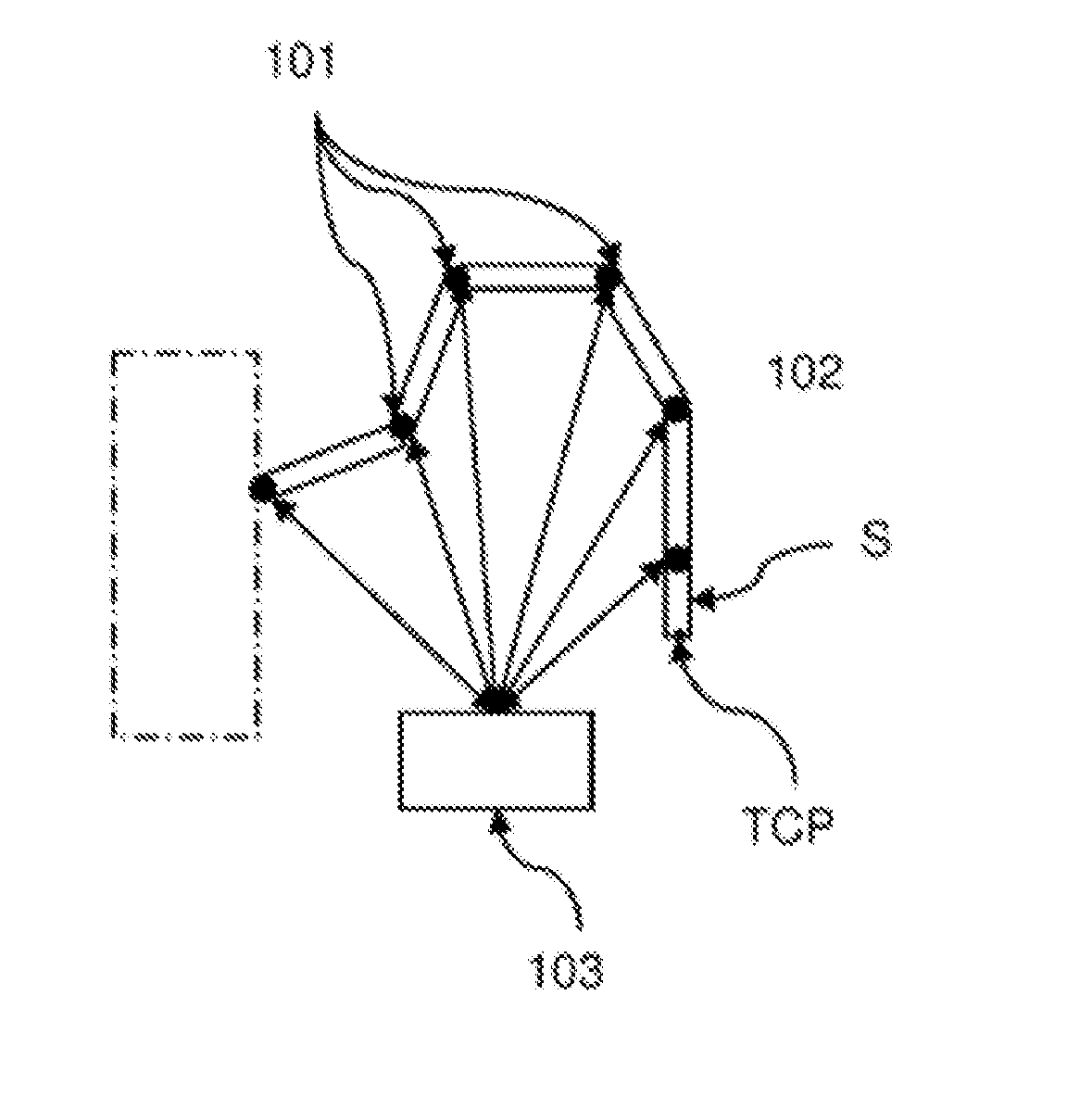
[0058] FIG. 1 shows a schematic representation of a proposed robot.
[0059] FIG. 1 shows a schematic representation of a proposed robot, comprising a movable, multi-membered robot structure 102 that can be driven by means of actuators 101, wherein at least one marked structural element S with at least one point P.sub.S marked on the structural element S is defined on the movable robot structure 102. The robot structure 102 is attached to a robot body (dashed box).
[0060] The robot structure 102 is presently a five-membered robot arm 102 at the distal end of which an effector S is arranged. In the present case, the effector S is the structural element S. At the effector S, a so-called "Tool Center Point"=TCP is defined, which is identical to the marked point P.sub.S=P.sub.TCP.
[0061] The robot is designed and set up in such a way that in an input mode the robot can learn positions POS.sub.TCP of the TCP and/or poses of the effector S in a work space of the robot, whereby the user, in order to move the effector S, exerts a force {right arrow over (F)}.sub.EING on the robot arm, which is conveyed to the point P.sub.TCP as {right arrow over (F)}.sub.EING,TCP and/or to the effector as {right arrow over (M)}.sub.EING,S.
[0062] The robot further comprises a control device which is embodied and configured in such a way that in the input mode the actuators 101 are controlled on the basis of a predetermined spatially fixed 3D virtual grid which at least partially fills the work space such that the effector S is moved with a given force {right arrow over (F)}.sub.GRID(POS.sub.TCP), which is dependent on the current position POS.sub.TCP of the tool center point TCP in the 3D grid, to the adjacent grid point of the 3D grid, wherein the point P.sub.TCP of the structural element S remains at this adjacent grid point if: |{right arrow over (F)}.sub.EING,PS|<|{right arrow over (F)}.sub.GRID(POS.sub.PS)|.
[0063] Moreover, the control device is configured in such a way that the actuators in the input mode are controlled based on a predetermined virtual discrete 3D orientation space O, wherein the 3D orientation space O=: (.alpha..sub.i, .beta..sub.j, .gamma..sub.k) with i=1, 2, . . . , I, j=1, 2, . . . J, k=1, 2, . . . , K is defined or definable by predetermined angles .alpha..sub.i, .beta..sub.j, .gamma..sub.k, controlled in such a way that the structural element S is moved by a predetermined torque {right arrow over (M)}.sub.O({right arrow over (O)}R.sub.S) depending on the current orientation {right arrow over (O)}R.sub.S of structural element S to the adjacent discrete orientation of the 3D orientation space O=: (.alpha..sub.i, .beta..sub.j, .gamma..sub.k), wherein the structural element S remains in this adjacent discrete orientation of the 3D orientation space O in the case where: |{right arrow over (M)}.sub.EING,S|<|{right arrow over (M)}.sub.O({right arrow over (O)}R.sub.S)|.
[0064] Although the invention has been detailed and explained by means of preferred exemplary embodiments, it is understood that the invention is not limited by the disclosed examples and that other variations may be derived by those skilled in the art, without leaving the protection scope of the invention. It is thus clear that a multiplicity of possible variants exists. It is also clear that the exemplary embodiments only represent examples, which are not intended to limit the protection scope, the possible applications or the configuration of the invention. The previous description and the description of the figures are actually construed in order to allow those skilled in the art to put the exemplary embodiments into practice, wherein those skilled in the art, based on the knowledge of the disclosed inventive idea, may introduce various modifications, for example regarding the functionality or the arrangement of individual elements cited in an exemplary embodiment, without leaving the protection scope, which is defined by the claims and their legal equivalents, as for example in a further explanation of the invention.
REFERENCE LIST
[0065] 101 actuators [0066] 102 movable, multi-membered robot structure [0067] 103 control device
* * * * *
D00000
D00001
XML
uspto.report is an independent third-party trademark research tool that is not affiliated, endorsed, or sponsored by the United States Patent and Trademark Office (USPTO) or any other governmental organization. The information provided by uspto.report is based on publicly available data at the time of writing and is intended for informational purposes only.
While we strive to provide accurate and up-to-date information, we do not guarantee the accuracy, completeness, reliability, or suitability of the information displayed on this site. The use of this site is at your own risk. Any reliance you place on such information is therefore strictly at your own risk.
All official trademark data, including owner information, should be verified by visiting the official USPTO website at www.uspto.gov. This site is not intended to replace professional legal advice and should not be used as a substitute for consulting with a legal professional who is knowledgeable about trademark law.