Virtual Roll Gyro for Spin-Stabilized Projectiles
Bortolami; Simone B. ; et al.
U.S. patent application number 16/027505 was filed with the patent office on 2019-02-21 for virtual roll gyro for spin-stabilized projectiles. The applicant listed for this patent is The Charles Stark Draper Laboratory, Inc.. Invention is credited to Simone B. Bortolami, Juha-Pekka J. Laine.
| Application Number | 20190056202 16/027505 |
| Document ID | / |
| Family ID | 63036355 |
| Filed Date | 2019-02-21 |
| United States Patent Application | 20190056202 |
| Kind Code | A1 |
| Bortolami; Simone B. ; et al. | February 21, 2019 |
Virtual Roll Gyro for Spin-Stabilized Projectiles
Abstract
A method is described for determining roll rate for a spin-stabilized projectile. A yaw signal and a pitch signal are measured for the projectile, wherein: (i) for a trajectory path being travelled by the projectile over the Earth's surface, projectile stability is created by spinning of the projectile about a longitudinal spin axis oriented tangent to the projectile trajectory, (ii) the yaw signal represents yaw motion of the projectile about a yaw axis oriented along a line through the Earth's center and orthogonal to the spin axis, and (iii) the pitch signal represents pitch motion of the projectile about a pitch axis orthogonal to the spin axis and the yaw axis, and wherein the yaw signal and the pitch signal are modulated by spin rate of the projectile spinning about the spin axis. A roll rate signal is extracted from one of the yaw signal and the pitch signal.
| Inventors: | Bortolami; Simone B.; (Belmont, MA) ; Laine; Juha-Pekka J.; (Boston, MA) | ||||||||||
| Applicant: |
|
||||||||||
|---|---|---|---|---|---|---|---|---|---|---|---|
| Family ID: | 63036355 | ||||||||||
| Appl. No.: | 16/027505 | ||||||||||
| Filed: | July 5, 2018 |
Related U.S. Patent Documents
| Application Number | Filing Date | Patent Number | ||
|---|---|---|---|---|
| 62528557 | Jul 5, 2017 | |||
| Current U.S. Class: | 1/1 |
| Current CPC Class: | F41G 9/00 20130101; F41G 7/36 20130101; G01C 21/10 20130101; F42B 10/26 20130101 |
| International Class: | F41G 9/00 20060101 F41G009/00; F42B 10/26 20060101 F42B010/26 |
Claims
1. A computer-implemented method employing at least one hardware implemented computer processor for determining roll rate for a spin-stabilized projectile, the method comprising: operating the at least one hardware processor to execute program instructions to: measure a yaw signal and a pitch signal for the projectile, wherein: (i) for a trajectory path being travelled by the projectile over the Earth's surface, projectile stability is created by spinning of the projectile about a longitudinal spin axis oriented tangent to the projectile trajectory, (ii) the yaw signal represents yaw motion of the projectile about a yaw axis oriented along a line through the Earth's center and orthogonal to the spin axis, (iii) the pitch signal represents pitch motion of the projectile about a pitch axis orthogonal to the spin axis and the yaw axis, and wherein the yaw signal and the pitch signal are modulated by spin rate of the projectile spinning about the spin axis; extract a roll rate signal from one of the yaw signal and the pitch signal; and provide the yaw signal, the pitch signal, and the roll rate signal to an inertial measurement unit (IMU) configured to control orientation of the projectile with respect to the trajectory path.
2. The method according to claim 1, wherein the yaw signal is measured by a yaw gyroscopic sensor within the projectile.
3. The method according to claim 1, wherein the pitch signal is measured by a pitch gyroscopic sensor within the projectile.
4. The method according to claim 1, wherein the roll rate signal is extracted by detecting zero crossings of one of the yaw signal and the pitch signal.
5. The method according to claim 1, wherein the roll rate signal is extracted by deconvolving one of the yaw signal and the pitch signal.
6. The method according to claim 1, wherein the IMU is configured to measure the yaw signal and the pitch signal.
7. The method according to claim 1, wherein the IMU is configured to extract the roll rate signal.
8. A non-transitory tangible computer-readable medium having instructions thereon for determining roll rate for a spin-stabilized projectile, the instructions comprising: program code for measuring a yaw signal and a pitch signal for the projectile, wherein: i. for a trajectory path being travelled by the projectile over the Earth's surface, projectile stability is created by spinning of the projectile about a longitudinal spin axis oriented tangent to the projectile trajectory, ii. the yaw signal represents yaw motion of the projectile about a yaw axis oriented along a line through the Earth's center and orthogonal to the spin axis, iii. the pitch signal represents pitch motion of the projectile about a pitch axis orthogonal to the spin axis and the yaw axis, and wherein the yaw signal and the pitch signal are modulated by spin rate of the projectile spinning about the spin axis; program code for extracting a roll rate signal from one of the yaw signal and the pitch signal; and program code for providing the yaw signal, the pitch signal, and the roll rate signal to an inertial measurement unit (IMU) configured to control orientation of the projectile with respect to the trajectory path.
9. The computer-readable medium according to claim 8, wherein the yaw signal is measured by a yaw gyroscopic sensor within the projectile.
10. The computer-readable medium according to claim 8, wherein the pitch signal is measured by a pitch gyroscopic sensor within the projectile.
11. The computer-readable medium according to claim 8, wherein the roll rate signal is extracted by detecting zero crossings of one of the yaw signal and the pitch signal.
12. The computer-readable medium according to claim 8, wherein the roll rate signal is extracted by deconvolving one of the yaw signal and the pitch signal.
13. The computer-readable medium according to claim 8, wherein the IMU is configured to measure the yaw signal and the pitch signal.
14. The computer-readable medium according to claim 8, wherein the IMU is configured to extract the roll rate signal.
Description
[0001] This application claims priority from U.S. Provisional Patent Application 62/528,557, filed Jul. 5, 2017, which is incorporated herein by reference in its entirety.
TECHNICAL FIELD
[0002] The present invention relates to spin-stabilized projectiles.
BACKGROUND ART
[0003] Spin-stabilized projectiles such as missiles and spacecraft rotate around a longitudinal axis that is approximately tangent to the flight trajectory. The spinning mass of the projectile creates gyroscopic forces that keep the spin axis resistant to the destabilizing forces. Course control of a spin-stabilized projectile can be performed by counter-rotation of an internal mass about the spin axis (e.g., on an internal boom). The projectile can be steered by controlling the positioning of the internal mass. See, e.g., U.S. Patent Publication 2012/0175458, which is incorporated herein by reference in its entirety.
[0004] Spin-stabilized projectiles include on-board navigation systems for flight-control and guidance. Inertia-based navigation systems typically use an inertial measurement unit (IMU) and one or more motion sensors (e.g., accelerometers) and rotation sensors (e.g., gyroscopes) to continuously calculate via dead reckoning the position, orientation, and velocity of a moving object such as spin stabilized projectile. Such arrangements typically use at least one gyro sensor and at least one accelerometer for each body axis for the IMU to measure all six degrees-of-freedom of the vehicle motion.
[0005] In strapdown inertial navigation systems, the inertial instruments are rigidly attached to the projectile. The sensor measurements then are transformed to a stabilized reference frame to remove the effects of vehicle motion. The transform computations are conceptually simple, but the implementation can be very complex because of the multiple rotating coordinate frames. The IMU measures the angular velocity and acceleration of the projectile relative to inertial coordinates, but these measurements are sensed in the rotating frame of the projectile body as denoted by the IMU coordinates x.sub.i, y.sub.i, z.sub.i. But, the desired navigation solution generally is given relative to a different rotating Earth-centered Earth-fixed (ECEF) coordinate frame, denoted by ECEF coordinates x.sub.e, y.sub.e, z.sub.e, with an angular velocity {right arrow over (.omega..sub.ie )} relative to the inertial frame. See, e.g., Bezick, Scott M., Alan J. Pue, and Charles M. Patzelt. "Inertial navigation for guided missile systems." Johns Hopkins APL technical digest 28.4 (2010): 331-342; which is incorporated herein by reference in its entirety.
SUMMARY
[0006] Embodiments of the present invention are directed to a method for determining roll rate for a spin-stabilized projectile. A yaw signal and a pitch signal are measured for the projectile, wherein: (i) for a trajectory path being travelled by the projectile over the Earth's surface, projectile stability is created by spinning of the projectile about a longitudinal spin axis oriented tangent to the projectile trajectory, (ii) the yaw signal represents yaw motion of the projectile about a yaw axis oriented along a line through the Earth's center and orthogonal to the spin axis, and (iii) the pitch signal represents pitch motion of the projectile about a pitch axis orthogonal to the spin axis and the yaw axis, and wherein the yaw signal and the pitch signal are modulated by spin rate of the projectile spinning about the spin axis. A roll rate signal is extracted from one of the yaw signal and the pitch signal. The yaw signal, the pitch signal, and the roll rate signal then are provided to an inertial measurement unit (IMU) configured to control orientation of the projectile with respect to the trajectory path.
[0007] In further specific embodiments, the yaw signal may be measured by a yaw gyroscopic sensor within the projectile, and/or the pitch signal may be measured by a pitch gyroscopic sensor within the projectile. The roll rate signal may be extracted by detecting zero crossings of one of the yaw signal and the pitch signal, and/or by deconvolving one of the yaw signal and the pitch signal. The IMU may be configured to measure the yaw signal and the pitch signal and/or to extract the roll rate signal.
BRIEF DESCRIPTION OF THE DRAWINGS
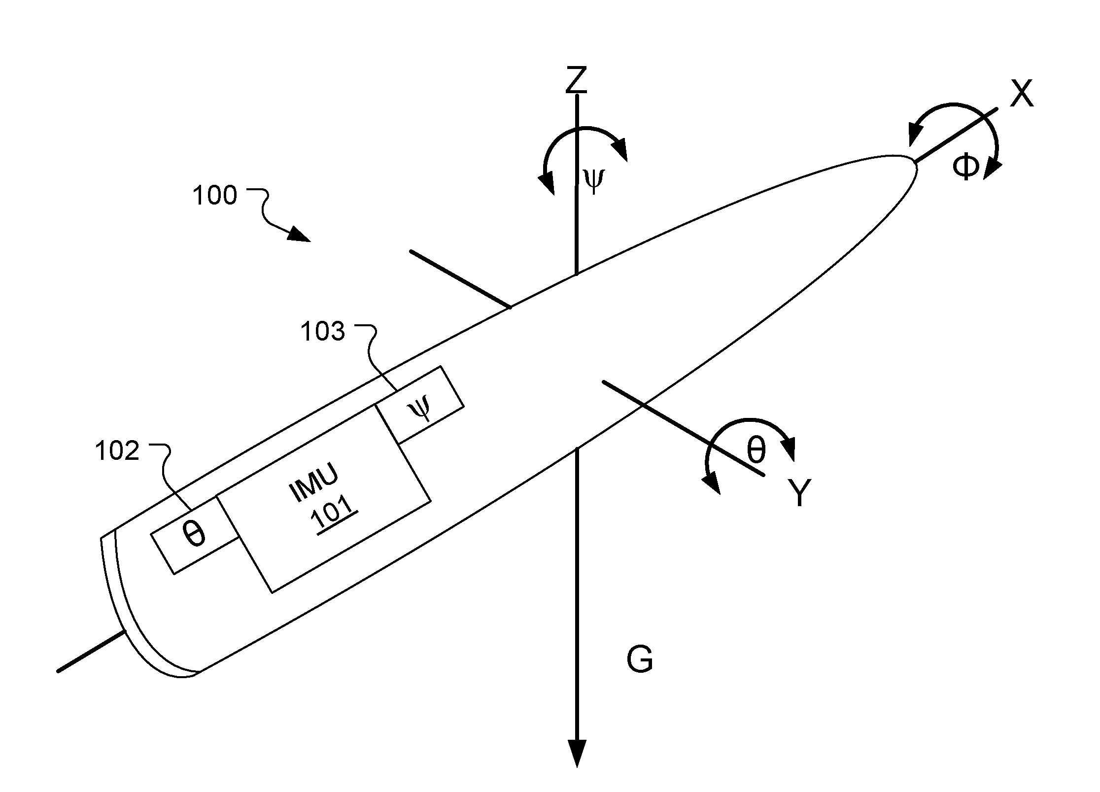
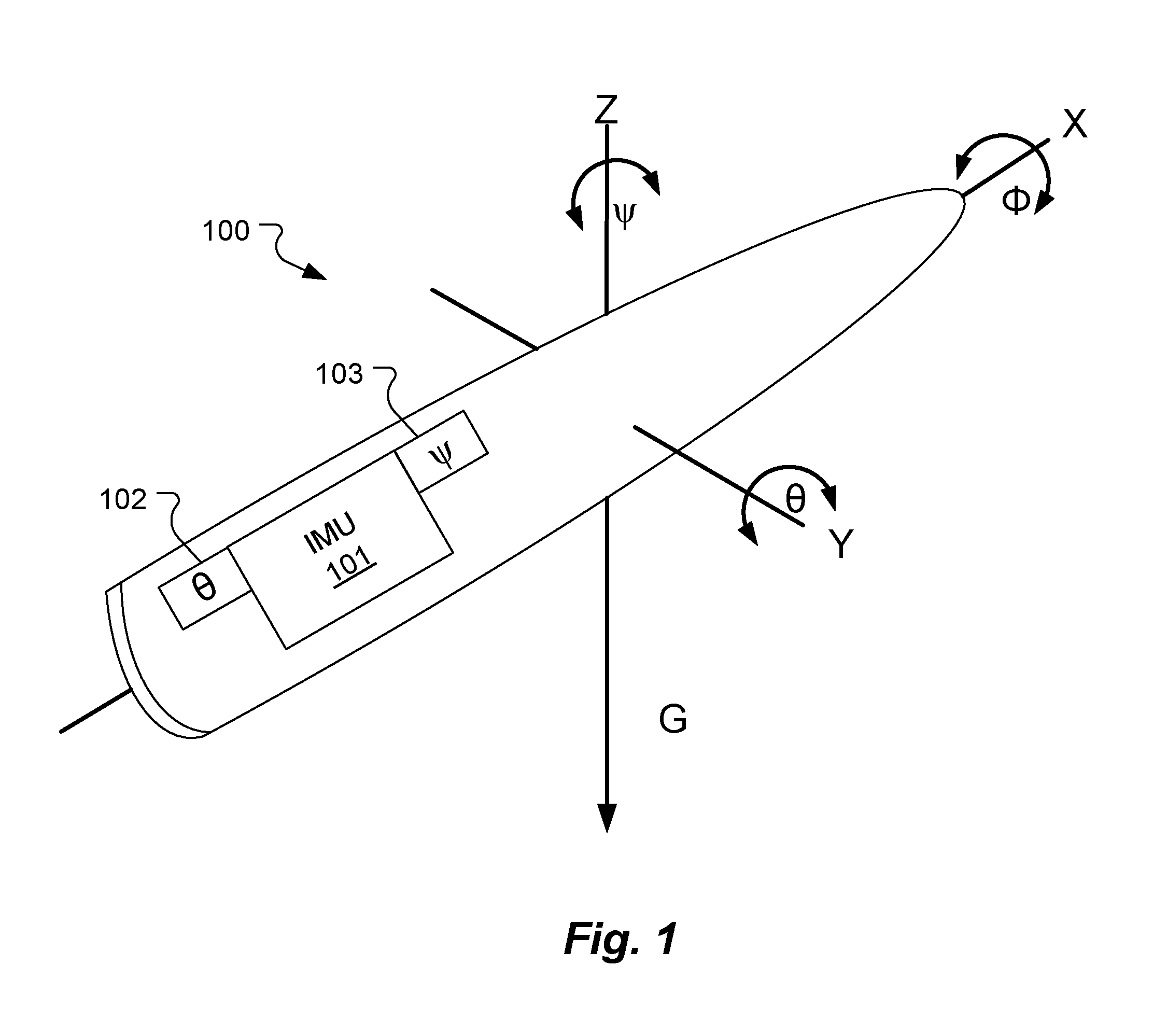
[0008] FIG. 1 shows various aspects of a spin stabilized projectile according to an embodiment of the present invention.
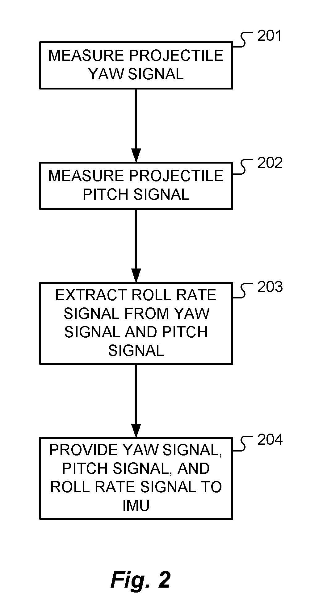
[0009] FIG. 2 shows various logical steps in a method according to an embodiment of the present invention.
DETAILED DESCRIPTION
[0010] Spun projectiles conventionally need to have a roll gyro sensor to monitor how the body frame rotates with respect to the direction of travel in order to be able to correct their trajectories, e.g., to the left or to the right. Such roll gyro sensors need to have a very good scale-factor performance and to allow for high spin rates. Generally, the part of the projectile containing the IMU is de-spun to reduced rates to allow for it to adequately operate. But embodiments of the present invention avoid those requirements and instead take advantage of the high spin rate of the projectile and avoid the usage of a dedicated roll gyro.
[0011] FIG. 1 shows various aspects of a spin stabilized projectile 100 and FIG. 2 shows various logical steps 201-204 in a method according to an embodiment of the present invention for determining roll rate for the spin-stabilized projectile 100 without using a roll gyro sensor. The projectile 100 has a relatively high rate of spin .PHI. about a longitudinal spin axis (x-axis) of the projectile 100 that stabilizes the projectile 100 on its trajectory (which is tangent to the spin axis). The projectile includes at least one yaw sensor 103 (e.g. a gyroscopic sensor) that measures a projectile yaw signal .psi., step 201, that represents yaw motion of the projectile 100 about a yaw axis (z-axis) that is oriented along a line through the Earth's center and orthogonal to the spin axis. A pitch sensor 102 (e.g., a gyroscopic sensor) measures a projectile pitch signal, step 202, that represents pitch motion of the projectile 100 about pitch axis (y-axis) that is orthogonal to the spin axis and the yaw axis.
[0012] An inertial measurement unit (IMU) 101 within the projectile 100 includes at least one hardware implemented processor device controlled by software instructions to control the orientation of the projectile 100 with respect to the trajectory path. The IMU 101 receives the yaw signal and the pitch signal, which are modulated by the high spin rate of the projectile spinning about the spin axis. The instructions performed by the IMU 101 then extracts a roll rate signal from one of the yaw signal and the pitch signal, step 203. For example, the IMU 101 my execute instruction to extract the roll rate signal by detecting the zero crossings of one of the yaw signal and the pitch signal. A properly designed observer or properly calibrated open loop arrangement can then extract the corrected and de-convolved roll rate. The IMU 101 then provides the yaw signal, the pitch signal, and the extracted roll rate signal, step 204, to further software processes, for example, to control the trajectory of the projectile 100.
[0013] In some specific embodiments, the pitch sensor 102 and/or the yaw sensor 103 may be separate devices from the IMU 101, while in other embodiments, the pitch sensor 102 and/or the yaw sensor 103 may be integrated into the package of the IMU 101.
[0014] Existing conventional arrangements for spin-stabilized projectiles are not known to use any sort of frequency measurement so as to eliminate the roll gyro as described above. Since the roll signal is convolved with the frequency characteristics of the yaw signal and the pitch signal, then missing any samples at such high spin rate could lead to an erroneous or inaccurate navigation solution. By enabling the roll gyro sensor to be eliminated, guidance packages for spin-stabilized projectiles can be less expensive and more reliable.
[0015] Embodiments of the invention may be implemented in part in any conventional computer programming language such as VHDL, SystemC, Verilog, ASM, etc. Alternative embodiments of the invention may be implemented as pre-programmed hardware elements, other related components, or as a combination of hardware and software components.
[0016] Embodiments can be implemented in part as a computer program product for use with a computer system. Such implementation may include a series of computer instructions fixed either on a tangible medium, such as a computer readable medium (e.g., a diskette, CD-ROM, ROM, or fixed disk) or transmittable to a computer system, via a modem or other interface device, such as a communications adapter connected to a network over a medium. The medium may be either a tangible medium (e.g., optical or analog communications lines) or a medium implemented with wireless techniques (e.g., microwave, infrared or other transmission techniques). The series of computer instructions embodies all or part of the functionality previously described herein with respect to the system. Those skilled in the art should appreciate that such computer instructions can be written in a number of programming languages for use with many computer architectures or operating systems. Furthermore, such instructions may be stored in any memory device, such as semiconductor, magnetic, optical or other memory devices, and may be transmitted using any communications technology, such as optical, infrared, microwave, or other transmission technologies. It is expected that such a computer program product may be distributed as a removable medium with accompanying printed or electronic documentation (e.g., shrink wrapped software), preloaded with a computer system (e.g., on system ROM or fixed disk), or distributed from a server or electronic bulletin board over the network (e.g., the Internet or World Wide Web). Of course, some embodiments of the invention may be implemented as a combination of both software (e.g., a computer program product) and hardware. Still other embodiments of the invention are implemented as entirely hardware, or entirely software (e.g., a computer program product).
[0017] Although various exemplary embodiments of the invention have been disclosed, it should be apparent to those skilled in the art that various changes and modifications can be made which will achieve some of the advantages of the invention without departing from the true scope of the invention.
* * * * *
D00000
D00001
D00002
XML
uspto.report is an independent third-party trademark research tool that is not affiliated, endorsed, or sponsored by the United States Patent and Trademark Office (USPTO) or any other governmental organization. The information provided by uspto.report is based on publicly available data at the time of writing and is intended for informational purposes only.
While we strive to provide accurate and up-to-date information, we do not guarantee the accuracy, completeness, reliability, or suitability of the information displayed on this site. The use of this site is at your own risk. Any reliance you place on such information is therefore strictly at your own risk.
All official trademark data, including owner information, should be verified by visiting the official USPTO website at www.uspto.gov. This site is not intended to replace professional legal advice and should not be used as a substitute for consulting with a legal professional who is knowledgeable about trademark law.