Cosmetic Dispenser With Piston Action
PORTER; KRISTOPHER ; et al.
U.S. patent application number 16/041274 was filed with the patent office on 2019-01-31 for cosmetic dispenser with piston action. This patent application is currently assigned to HCT GROUP HOLDINGS LIMITED. The applicant listed for this patent is HCT GROUP HOLDINGS LIMITED. Invention is credited to ANTHONY DEMARCO, JUNG HAN, KRISTOPHER PORTER, ROBERT STEINHAUER, RALPH VESTBOM, ROBERT WILCZYNSKI.
| Application Number | 20190029395 16/041274 |
| Document ID | / |
| Family ID | 65137979 |
| Filed Date | 2019-01-31 |


| United States Patent Application | 20190029395 |
| Kind Code | A1 |
| PORTER; KRISTOPHER ; et al. | January 31, 2019 |
COSMETIC DISPENSER WITH PISTON ACTION
Abstract
A cosmetic product dispenser having a body with a chamber for containing a product, the body having an open first end with an actuating structure thereon and a second end having a neck with a product passageway therein, a receiver receiving and engaging with the body, a piston adapted to slide within the chamber, and a piston holder to hold the piston in a relative position relative to the receiver. To dispense product, the body is rotated or twisted relative to the receiver, causing the body to draw into the receiver and pushing the piston into the body, expelling product via the product passageway. The overall structure becomes shorter as product is dispensed.
| Inventors: | PORTER; KRISTOPHER; (NEW WINDSOR, NY) ; VESTBOM; RALPH; (CLIFFSIDE PARK, NJ) ; STEINHAUER; ROBERT; (STONY BROOK, NY) ; DEMARCO; ANTHONY; (MAHWAH, NJ) ; HAN; JUNG; (NEW YORK, NY) ; WILCZYNSKI; ROBERT; (PERTH AMBOY, NJ) | ||||||||||
| Applicant: |
|
||||||||||
|---|---|---|---|---|---|---|---|---|---|---|---|
| Assignee: | HCT GROUP HOLDINGS LIMITED CENTRAL CN |
||||||||||
| Family ID: | 65137979 | ||||||||||
| Appl. No.: | 16/041274 | ||||||||||
| Filed: | July 20, 2018 |
Related U.S. Patent Documents
| Application Number | Filing Date | Patent Number | ||
|---|---|---|---|---|
| 62538108 | Jul 28, 2017 | |||
| Current U.S. Class: | 1/1 |
| Current CPC Class: | A45D 2200/1045 20130101; A45D 2200/1018 20130101; A45D 2200/055 20130101; A45D 34/04 20130101 |
| International Class: | A45D 34/04 20060101 A45D034/04 |
Claims
1. A cosmetic dispenser comprising: a body having a chamber for containing a product having an open lower end having an outer facing actuating structure, and an upper end with a neck having a product passageway; a piston adapted to slide within the body chamber from the lower end thereof; a piston holder for supporting the piston; and a receiver for the body comprising an inner facing engaging structure for engaging the outer facing actuating structure of the body, the receiver having a lower portion configured to engage and secure to the piston holder; wherein the body is coupled to the receiver and the piston holder and piston holder are coupled to the receiver such that twisting of the body relative to the receiver causes axial motion of the piston within the body due to interaction of the actuating structure of the body with the engaging structure of the receiver, thereby dispensing product from the body via the product passageway.
2. The dispenser of claim 1 wherein the neck comprises an outer facing engagement structure for securing a product applicator thereon.
3. A combination cosmetic dispenser and applicator comprising: a product dispenser as in claim 2; and a product applicator secured to the body using the outer facing engagement structure of the neck.
4. The combination of claim 3 wherein the product applicator comprises a sponge coupled to inner and outer collars, and the inner collar is secured to the engagement structure of the neck to fix the product applicator and outer collar to the body.
5. The combination of claim 4 wherein the engagement structure of the neck comprises threading, and the inner collar comprises corresponding threading for securing the inner collar to the engagement structure of the neck.
6. The dispenser of claim 1 wherein the body has a length including a first portion on which the actuating structure resides and a second portion extending from the first portion toward the upper end, and the body, piston and receiver are coupled together such that: when the body is full of product, the piston extends partially into the body and the second portion of the body extends out from the receiver, with the first portion of the body in the receiver such that the actuating structure of the body engages the engaging structure of the receiver; and a twisting motion of the body relative to the receiver will cause the piston to advance within the body and expel product as the receiver engaging structure interacts with the actuating structure of the body to draw the body into the receiver.
7. The dispenser of claim 6 wherein the piston holder includes an elongate section holding the piston at a first end and having a stop at a second end for engaging the receiver.
8. The dispenser of claim 7 wherein: the second end of the piston holder further comprises first teeth; the receiver comprises second teeth; and the first and second teeth configured for rotationally engaging the receiver and preventing rotation therebetween.
9. The dispenser of claim 1 further comprising a base shell for securing to an outer surface of the receiver, such that the base shell, receiver and piston holder are axially and rotationally secured together.
10. A dispenser as in claim 1 wherein the piston is configured to seal against an inner wall of the body.
11. A dispenser as in claim 1 further comprising a cap having a plug configured to seal an upper end of the product passageway.
12. A dispenser as in claim 11 wherein: the dispenser has a first end at which the piston holder and the receiver are secured together and a second end at which the cap is placed defining an axial length therebetween; when the body is full of product, the axial length is a first value; and when the body is empty of product, the axial length is a second value less than the first value.
13. A method of dispensing a cosmetic product using a dispenser, the dispenser comprising: a body having a chamber for containing a product having an open lower end having an outer facing actuating structure, and an upper end with a neck having a product passageway; a piston adapted to slide within the body chamber from the lower end thereof; a piston holder for supporting the piston; and a receiver for the body comprising an inner facing engaging structure for engaging the outer facing actuating structure of the body, the receiver having a lower portion configured to engage and secure to the piston holder; wherein the body is coupled to the receiver and the piston holder and piston holder are coupled to the receiver such that twisting of the body relative to the receiver causes axial motion of the piston within the body due to interaction of the actuating structure of the body with the engaging structure of the receiver, thereby dispensing product from the body via the product passageway, the method comprising twisting the body relative to the receiver to expel product via the product passageway.
Description
CROSS REFERENCE TO RELATED APPLICATIONS
[0001] The present application claims the benefit of and priority to U.S. Provisional Patent Application Ser. No. 62/538,108, filed on Jul. 28, 2017, the disclosure of which is incorporated herein by reference.
BACKGROUND
[0002] Numerous examples of cosmetic dispensers are available in the art. New and alternative configurations offering unique and different dispenser designs and techniques of operation are in demand.
OVERVIEW
[0003] A first illustrative and non-limiting example takes the form of a cosmetic dispenser comprising a body having a chamber for containing a product having an open lower end having an outer facing actuating structure, and an upper end with a neck having a product passageway; a piston adapted to slide within the body chamber from the lower end thereof; a piston holder for supporting the piston; and a receiver for the body comprising an inner facing engaging structure for engaging the outer facing actuating structure of the body, the receiver having a lower portion configured to engage and secure to the piston holder; wherein the body is coupled to the receiver and the piston holder and piston holder are coupled to the receiver such that twisting of the body relative to the receiver causes axial motion of the piston within the body due to interaction of the actuating structure of the body with the engaging structure of the receiver, thereby dispensing product from the body via the product passageway.
[0004] Additionally or alternatively, the neck may comprise an outer facing engagement structure for securing a product applicator thereon.
[0005] Additionally or alternatively, the body may have a length including a first portion on which the actuating structure resides and a second portion extending from the first portion toward the upper end, and the body, piston and receiver are coupled together such that: when the body is full of product, the piston extends partially into the body and the second portion of the body extends out from the receiver, with the first portion of the body in the receiver such that the actuating structure of the body engages the engaging structure of the receiver; and a twisting motion of the body relative to the receiver will cause the piston to advance within the body and expel product as the receiver engaging structure interacts with the actuating structure of the body to draw the body into the receiver.
[0006] Additionally or alternatively, the piston holder may include an elongate section holding the piston at a first end and having a stop at a second end for engaging the receiver.
[0007] Additionally or alternatively, the second end of the piston holder further comprises first teeth; the receiver comprises second teeth; and the first and second teeth configured for rotationally engaging the receiver and preventing rotation therebetween.
[0008] Additionally or alternatively, the dispenser may further comprise a base shell for securing to an outer surface of the receiver, such that the base shell, receiver and piston holder are axially and rotationally secured together.
[0009] A second illustrative and non-limiting example takes the form of a combination cosmetic dispenser and applicator comprising a product dispenser as in the first illustrative and non-limiting example and/or variants thereof, and a product applicator secured to the body using the outer facing engagement structure of the neck.
[0010] Additionally or alternatively, the product applicator may comprise a sponge coupled to inner and outer collars, and the inner collar is secured to the engagement structure of the neck to fix the product applicator and outer collar to the body.
[0011] Additionally or alternatively, the engagement structure of the neck comprises threading, and the inner collar comprises corresponding threading for securing the inner collar to the engagement structure of the neck.
[0012] Additionally or alternatively, dispenser or combination may be such that the piston is configured to seal against an inner wall of the body.
[0013] Additionally or alternatively, the dispenser or combination may further comprise a cap having a plug configured to seal an upper end of the product passageway.
[0014] Additionally or alternatively, the dispenser may have a first end at which the piston holder and the receiver are secured together and a second end at which the cap is placed defining an axial length therebetween; when the body is full of product, the axial length is a first value; and when the body is empty of product, the axial length is a second value less than the first value.
[0015] Another illustrative, non-limiting example, may take the form of a method of dispensing a cosmetic product using a dispenser or combination as either of the first or second illustrative, non-limiting examples, or variants thereof, by twisting the body relative to the receiver to expel product via the product passageway.
[0016] This overview is intended to provide an introduction to the subject matter of the present patent application. It is not intended to provide an exclusive or exhaustive explanation of the invention. The detailed description is included to provide further information about the present patent application.
BRIEF DESCRIPTION OF THE DRAWINGS
[0017] In the drawings, which are not necessarily drawn to scale, like numerals may describe similar components in different views. Like numerals having different letter suffixes may represent different instances of similar components. The drawings illustrate generally, by way of example, but not by way of limitation, various embodiments discussed in the present document.
[0018] FIG. 1 is a perspective view of a cosmetic dispenser with a cap;
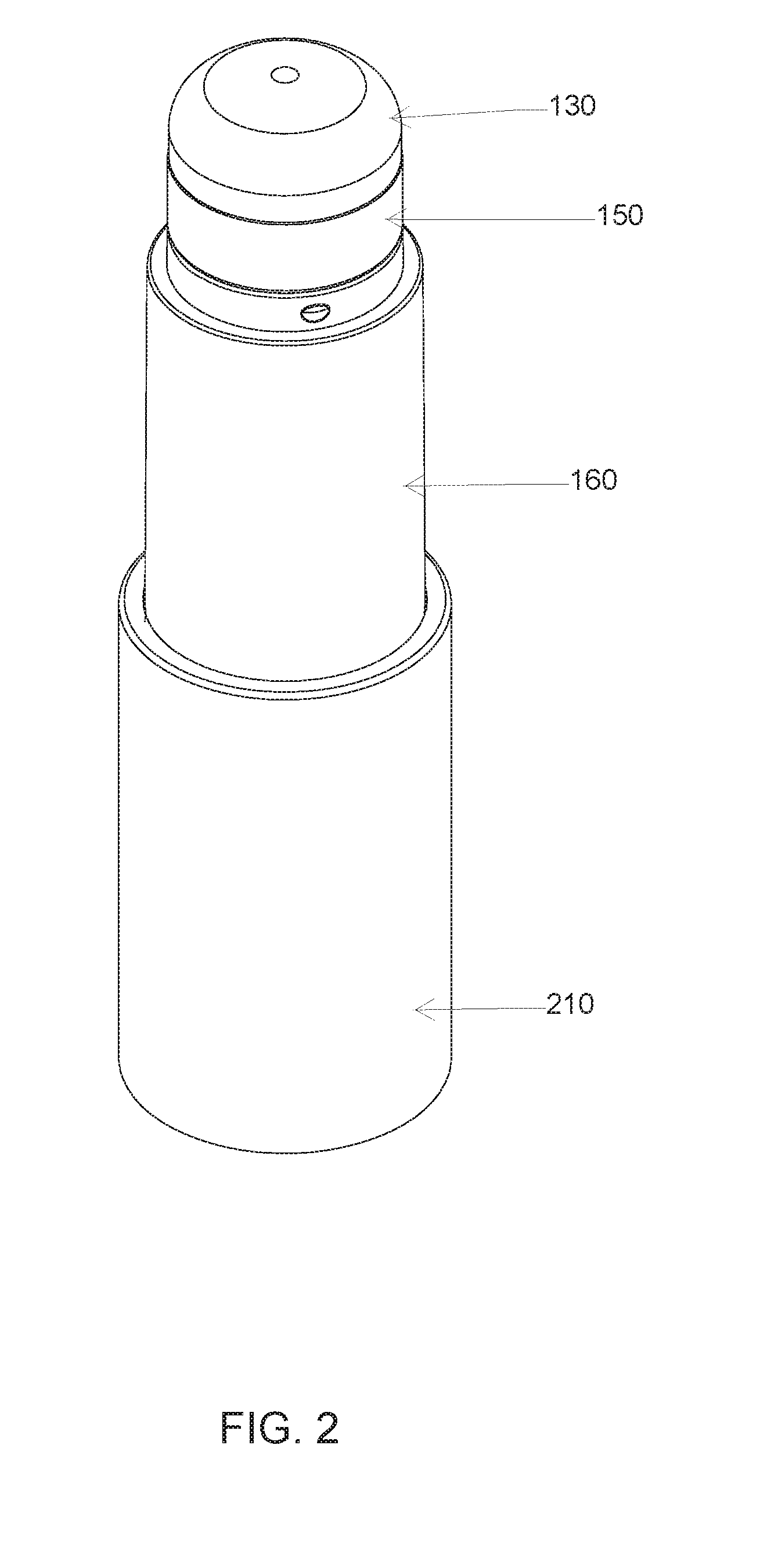
[0019] FIG. 2 is a perspective view as in FIG. 1 with the cap removed to illustrate the dispenser and applicator;
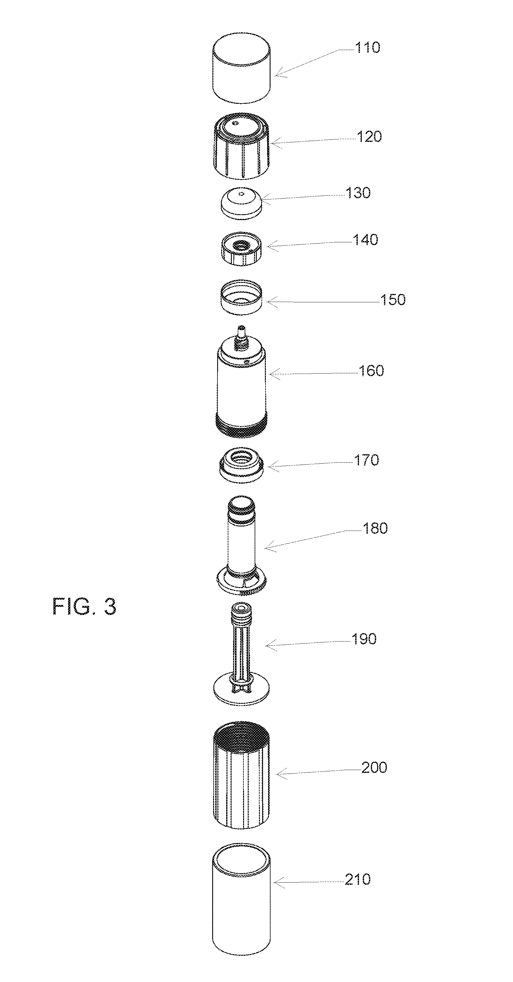
[0020] FIG. 3 is an exploded view showing the parts of an illustrative dispenser;
[0021] FIG. 4 shows a body for containing product in isolation;
[0022] FIG. 5 shows a piston and piston holder;
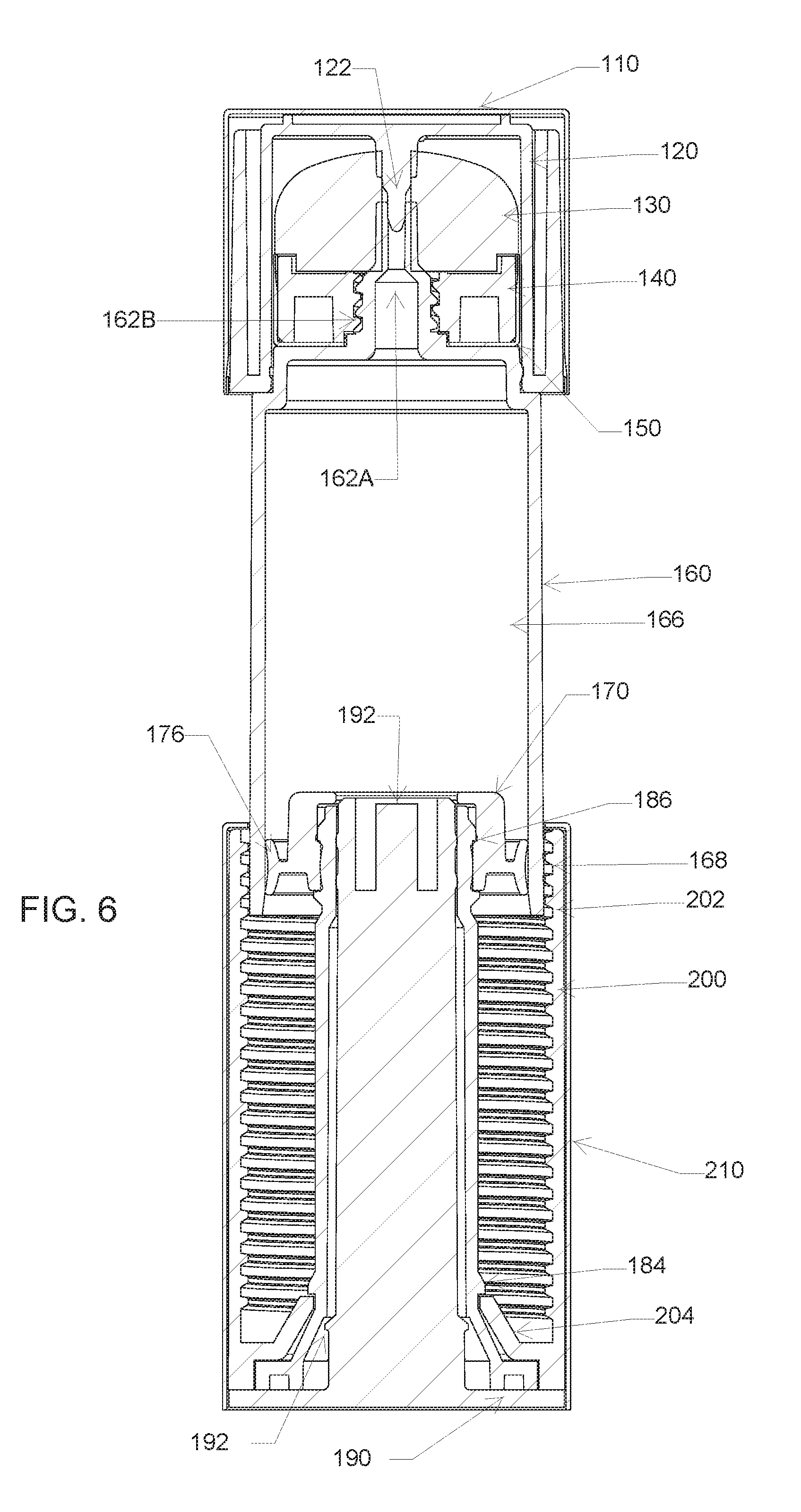
[0023] FIG. 6 shows a cross section of a cosmetic dispenser with applicator and cap in an extended form for when the body thereof is full of cosmetic product;
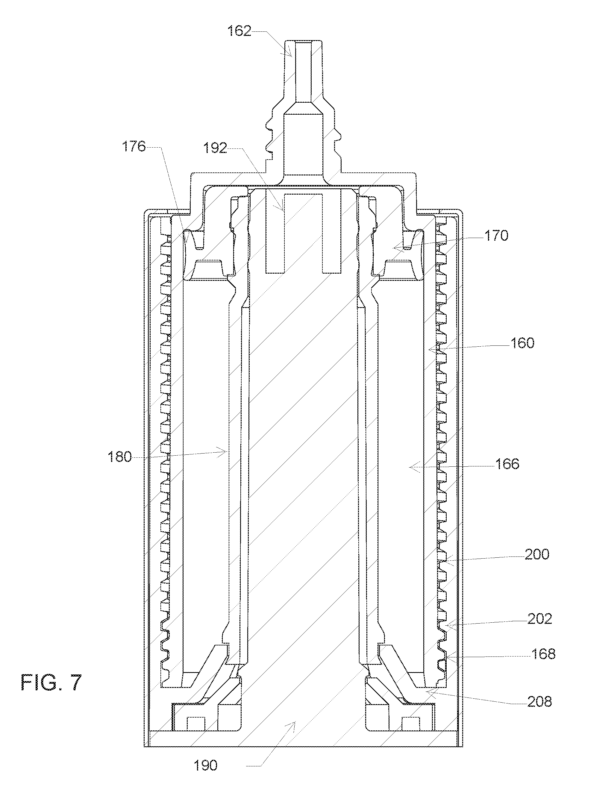
[0024] FIG. 7 shows a cross section of a cosmetic dispenser in retracted form for when the body has been emptied of product; and
[0025] FIG. 8 is a side elevation view of a cosmetic dispenser with a cap.
DETAILED DESCRIPTION
[0026] FIG. 1 is a perspective view of a cosmetic dispenser with a cap. The dispenser comprises a cap 110 shown atop a body 160, with the body extending into a base shell 210. The configuration shown in FIG. 1 is a "full" configuration, in which the body is filled with a cosmetic product. The cosmetic product may be, for example, a foundation product. Other products may be provided instead including, for example and without limitation, mascara, lip gloss, eye liner, concealer, eye primer, lash primer, lip stain, nail polish, polish remover, and other products applied via brushes, sponges, or other cosmetic applicators.
[0027] As the product is used, the body 160 can be rotated or twisted relative to the base shell 210, expelling product as discussed below, until the configuration shown in FIG. 8 is achieved, in which the cap 110 lies more or less adjacent the base shell 210, with the body 160 mostly contained within the base shell.
[0028] FIG. 2 is a perspective view as in FIG. 1 with the cap removed to illustrate the dispenser and applicator. The upper portion of the body is shown with an applicator 130, which may be, for example, a sponge, metal, stone, ceramic, glass, a flexible or hard plastic, rubber or polymer, a gel, or a multiple piece member including for example, a metal portion and a plastic portion. A brush may be provided instead as the applicator 130. Other parts of the body may be made of any suitable materials, such as plastic (for example, polypropylene, acrylonitrile butadiene styrene, polyoxymethylene or other plastics, preferably ones which are non-reactive with the cosmetic products to be used), glass, metal, wood, composites thereof, or any other suitable material, for containing a cosmetic, medicinal, personal care, or other product.
[0029] An outer collar 150 is visible and is held in place by an inner collar (not shown) which attaches to the top of the body 160 as shown below, as well as being secured to the applicator 130 by, without limitation, snap fit, threaded attachment, press fit, heat attachment, or adhesive, for example. Again the body 160 extends into the base shell 210.
[0030] FIG. 3 is an exploded view showing the parts of an illustrative dispenser. Cap 110 is actual an outer shell in this example that is fitted (press fit, snap fit and/or adhesive, for example) on an inner cap 120 which. The applicator is shown at 130 adjacent to the inner collar 140. The inner collar 140 would be affixed to the applicator 140 as previously explained, and also secured to the body 160 in order to hold a decorative or protective outer collar 150 in place. The body 160 is shown in greater detail below in FIG. 4. A piston 170 is also provided and secures to a piston holder 180. A plug 190 is provided to secure inside the piston holder 180; in some examples, the plug 190 may be integral with the piston holder 180 instead. The base shell 210 fits around a receiver 200.
[0031] The receiver 200, as shown and explained further below, is adapted to mate with and be secured to the piston holder 180 and includes a structure on an inner face thereof, such as threads, that engage with corresponding structure on the lower portion of the body 160. A twisting motion between the body 160 and the receiver 200 is translated to axial motion of the body 160 relative to the piston 170, as further explained below, in order to expel product from a chamber within the body 160.
[0032] FIG. 4 shows a body for containing product in isolation. The body 160 includes a neck at 162 which defines a product passageway 162A through its interior and has an outer facing engagement structure 162B, shown here as threading, for securing a product applicator over the neck. The outer facing engagement structure 162B may operate to directly attach to a product applicator or may be for holding a collar or ferrule for a product applicator. A snap fit may be used instead of threading by providing a ring over which a snap fitting collar or the like may be placed and secured. In some examples, the outer facing engagement structure 162B may be omitted and a product applicator secured, for example, by adhesive or by having a neck of its own that can insert into the product delivery passageway 162A.
[0033] A cap receiving region is shown at 164 and may include structure(s) to aid in holding a cap on top of the body 160 such as, for example and without limitation, threading, a snap ring, indentations, or protrusions, such as protrusion 164A. A main portion of the body is shown at 166 and defines an interior chamber for holding a cosmetic product. While the top end of the main portion is closed as shown, the lower end (not shown) is generally open. The lower end of the body includes an actuating structure as shown at 168. The actuating structure 168 is shown as threading that extends generally all the way around the body 160; a lesser portion of the circumference may include the threading if desired.
[0034] FIG. 5 shows a piston and piston holder. The piston is shown at 170 and includes a body 172 that secures by snap fit onto the piston holder 180. Adhesive, screw fit, press fit, or other manners of securing the piston 170 to the piston holder 180 may be used in addition or instead. The piston includes a through passageway as shown at 174. In use, the through passageway may be used to allow filling at the end of manufacturing before a plug (shown in FIG. 6) is inserted. In an alternative embodiment, the passageway 174 may be omitted and the device is instead configured to be assembled with a body that is preloaded with product.
[0035] The outer portion of the piston includes a sealing member as shown at 176. A sealing member may be an elastomer, rubber, cork, or various plastics/polymers that allow for sealing (and which are compatible with) the product to be dispensed relative to a surface. In some embodiments, the outer profile of the sealing member 176 is circular or oval; other shapes may be used instead, though for ease of manufacture to yield a good seal, circular or oval are generally simpler. The sealing member 176 is sized and shaped to match an inner profile of the body (see FIG. 6).
[0036] The piston 170 is held in place by a piston holder 180. The base of the piston holder 180 comprises, optionally, teeth 182, which are used to engage with a receiver (see FIG. 6) to prevent rotation therebetween. A polygonal shape may be used instead of teeth 182. A securing structure is shown at 184 for securing to the receiver (see FIG. 6) to prevent axial motion between the receiver and the piston holder 180.
[0037] In some examples, the piston 170 is designed to be secured such that is cannot rotate relative to the piston holder 180. In other examples, particularly where the sealing member is non-circular, the piston holder and piston may allow rotation of the piston relative to the piston holder. In further embodiments, the piston holder 180 may omit the teeth 182 and/or polygon and allow the piston holder 180 to rotate relative to the receiver, if desired.
[0038] FIG. 6 shows a cross section of a cosmetic dispenser with applicator and cap in an extended form for when the body thereof is full of cosmetic product. Beginning at the top of the Figure, the cap shell is shown at 110 and is a thin piece provided largely for decorative and/or protective purposes, and which may be made of a metal or hard plastic, for example. The cap shell 110 is secured over an inner cap 120 which may include a structure as shown at 122 that is adapted to enter and generally seal shut the upper end of the product delivery passageway 162A through the neck 162 of the body 160. Element 122 may be referred to as a pintle, in that it is generally pin-like. In the example shown, the pintle 122 extends through the entire thickness of the product applicator 130. A pintle 122 may be omitted in other examples. The inner cap 120 may be made for example of any suitable polymer.
[0039] The product applicator 130 is seated using, for example, press fit, snap fit, threading, or adhesive, or other securing method, to an inner collar 140. A decorative and/or protective outer collar is provided as shown at 150 (more easily seen in earlier Figures). The inner collar 140 is secured to the outer facing engaging structure 162B and may be snap fit, press fit, and/or adhesively secured to the outer collar 150; or, alternatively, the outer collar 150 may simply be held in place by the inner collar being secured to structure 162B.
[0040] The overall applicator structure may include the actual applicator 130 (which may be any of various actual structures as noted above, such as a sponge, metal or gel), the inner collar 140 and the outer collar 150.
[0041] The body 160 defines a chamber 166 for receiving a cosmetic product. The lower portion of the body 160 includes the actuating structure 168 which is shown as being coupled to the engaging structure 202 of the receiver 200. Here, the engaging structure 202 is shown as threading that extends for most of the length of the interior of the receiver 200. Twisting the receiver 200 relative to the body 160 will, by action of the actuating structure 168 interacting with the engaging structure 202, cause the body 160 to be drawn into the receiver 200.
[0042] The receiver 200 is secured to the piston holder 180 in two ways. For prevention of axial motion of the receiver 200 relative to the piston holder 180, the snap fit ring 184 of the piston holder is engaged with an interior collar 204 of the receiver 200. In addition, though not shown, the teeth of the piston holder 180 mate with corresponding teeth of the receiver 200, preventing rotational motion therebetween. The receiver 200 sits within the base shell 210, to which it may be snap fit, press fit, or adhered.
[0043] The piston 170 is held in place on top of the piston holder 180 and resides, as shown here, into the lower portion of the chamber 166 of the body 160. The sealing member 176 rests flexibly against the inner wall of the body 160, as shown, creating a seal. A plug 190 is shown and may include an upper end 192 adjacent to the through hole of the piston 170. The plug 190 may be snap fit, press fit, and/or heat or chemically adhered into place. In the illustrative example, the plug 190 snap fits as shown at 192 to the piston holder 180.
[0044] Thus, as shown here, the body 160 is coupled to the receiver 200 and the piston holder 180 and piston 170 are coupled to the receiver 200 such that twisting of the body 160 relative to the receiver 200 causes axial motion of the piston 170 within the body 160 due to interaction of the actuating structure 168 of the body with the engaging structure 202 of the receiver 200, thereby dispensing product from the body 160 via the product passageway 162A. Such twisting motion will draw the body 160 into the receiver 200 until the product is entirely dispensed, achieving a configuration as shown in FIG. 7.
[0045] It may be noted that the actuating structure 168 of the body 160 may have a structure other than threads. For example and without limitation, tabs or posts adapted to engage a threaded structure of the receiver 200 may be provided instead. In the example shown, the actuating structure 168 traverses a small fraction of the length of the body 160 in order to provide a smooth exterior; as a result, the engagement structure (here, threading 202) in the receiver 200 extends most of the length of the receiver 200. In an alternative, the body 160 may have threading over almost all of its length, providing a different look and feel from an aesthetic perspective, while the receiver 200 includes a shorter portion of threading 202 or includes tabs or posts instead.
[0046] FIG. 7 shows a cross section of a cosmetic dispenser in retracted form for when the body has been emptied of product. In this Figure, the cap and applicator structures have been omitted to allow easier viewing of the rest of the device; it should be understood that in use such elements would be present. Here, the actuating structure 168 of the body 160 has traversed the length of the engaging structure 202 of the receiver 200, until reaching the base or stop of the receiver 200, as shown at 208. During this process, the piston holder 180, being secured to the receiver 200 as shown at 184, advances the piston 170 axially into the product holding chamber of the body 160.
[0047] FIG. 8 is a side elevation view of a cosmetic dispenser with a cap. Here, all the product has been expelled from the device as indicated by the cap shell 110 now being adjacent to the base shell 210, with the body no longer visible. This end point is merely illustrative; the body could still be visible in other embodiments.
[0048] Each of these non-limiting examples can stand on its own, or can be combined in various permutations or combinations with one or more of the other examples.
[0049] The above detailed description includes references to the accompanying drawings, which form a part of the detailed description. The drawings show, by way of illustration, specific embodiments in which the invention can be practiced. These embodiments are also referred to herein as "examples." Such examples can include elements in addition to those shown or described. However, the present inventors also contemplate examples in which only those elements shown or described are provided. Moreover, the present inventors also contemplate examples using any combination or permutation of those elements shown or described (or one or more aspects thereof), either with respect to a particular example (or one or more aspects thereof), or with respect to other examples (or one or more aspects thereof) shown or described herein.
[0050] In the event of inconsistent usages between this document and any documents so incorporated by reference, the usage in this document controls. In this document, the terms "a" or "an" are used, as is common in patent documents, to include one or more than one, independent of any other instances or usages of "at least one" or "one or more." Moreover, in the following claims, the terms "first," "second," and "third," etc. are used merely as labels, and are not intended to impose numerical requirements on their objects. The above description is intended to be illustrative, and not restrictive. For example, the above-described examples (or one or more aspects thereof) may be used in combination with each other. Other embodiments can be used, such as by one of ordinary skill in the art upon reviewing the above description.
[0051] The Abstract is provided to comply with 37 C.F.R. .sctn. 1.72(b), to allow the reader to quickly ascertain the nature of the technical disclosure. It is submitted with the understanding that it will not be used to interpret or limit the scope or meaning of the claims.
[0052] Also, in the above Detailed Description, various features may be grouped together to streamline the disclosure. This should not be interpreted as intending that an unclaimed disclosed feature is essential to any claim. Rather, inventive subject matter may lie in less than all features of a particular disclosed embodiment. Thus, the following claims are hereby incorporated into the Detailed Description as examples or embodiments, with each claim standing on its own as a separate embodiment, and it is contemplated that such embodiments can be combined with each other in various combinations or permutations. The scope of the invention should be determined with reference to the appended claims, along with the full scope of equivalents to which such claims are entitled.
* * * * *
D00000
D00001
D00002
D00003
D00004
D00005
D00006
D00007
D00008
XML
uspto.report is an independent third-party trademark research tool that is not affiliated, endorsed, or sponsored by the United States Patent and Trademark Office (USPTO) or any other governmental organization. The information provided by uspto.report is based on publicly available data at the time of writing and is intended for informational purposes only.
While we strive to provide accurate and up-to-date information, we do not guarantee the accuracy, completeness, reliability, or suitability of the information displayed on this site. The use of this site is at your own risk. Any reliance you place on such information is therefore strictly at your own risk.
All official trademark data, including owner information, should be verified by visiting the official USPTO website at www.uspto.gov. This site is not intended to replace professional legal advice and should not be used as a substitute for consulting with a legal professional who is knowledgeable about trademark law.