Electronic Devices And Methods For Gernerating Displayed Image
KO; Chueh-Pin
U.S. patent application number 15/913755 was filed with the patent office on 2019-01-10 for electronic devices and methods for gernerating displayed image. The applicant listed for this patent is Acer Incorporated. Invention is credited to Chueh-Pin KO.
| Application Number | 20190012057 15/913755 |
| Document ID | / |
| Family ID | 64903846 |
| Filed Date | 2019-01-10 |


| United States Patent Application | 20190012057 |
| Kind Code | A1 |
| KO; Chueh-Pin | January 10, 2019 |
ELECTRONIC DEVICES AND METHODS FOR GERNERATING DISPLAYED IMAGE
Abstract
An electronic device includes a touch-sensing module, an image-display control module, and a display. The touch-sensing module senses a touch event corresponding to at least one touch object, and outputs a position signal based on the touch event. The image-display control module connects to the touch-sensing module through a channel, receives the position signal via the channel from the touch-sensing module, and refreshes at least a portion of a current displayed image according to the position signal. The display displays a refreshed displayed image.
| Inventors: | KO; Chueh-Pin; (New Taipei City, TW) | ||||||||||
| Applicant: |
|
||||||||||
|---|---|---|---|---|---|---|---|---|---|---|---|
| Family ID: | 64903846 | ||||||||||
| Appl. No.: | 15/913755 | ||||||||||
| Filed: | March 6, 2018 |
| Current U.S. Class: | 1/1 |
| Current CPC Class: | G06F 9/451 20180201; G06F 1/3262 20130101; G06F 3/0412 20130101; G06F 3/0488 20130101 |
| International Class: | G06F 3/0488 20060101 G06F003/0488; G06F 3/041 20060101 G06F003/041; G06F 9/451 20060101 G06F009/451 |
Foreign Application Data
| Date | Code | Application Number |
|---|---|---|
| Jul 10, 2017 | TW | 106123018 |
Claims
1. An electronic device, comprising: a touch-sensing module, sensing a touch event corresponding to at least one touch object, and outputting a position signal based on the touch event; an image-display control module, connected to the touch-sensing module through a channel, receiving the position signal via the channel from the touch-sensing module, and updating at least a portion of a current displayed image according to the position signal; and a display, displaying an refreshed displayed image.
2. The electronic device as claimed in claim 1, further comprising: a storage unit, connected to the image-display control module, configured to store at least one first user interface; wherein the image-display control module further loads the first user interface from the storage unit, and displays the refreshed displayed image through the first user interface.
3. The electronic device as claimed in claim 2, wherein the image-display control module further stores the refreshed displayed image in the storage unit.
4. The electronic device as claimed in claim 3, further comprising: a processor, connected between the touch-sensing module and the display-control module, configured to receive the position signal from the touch-sensing module according to a wake-up signal, and control the touch-sensing module to stop outputting the position signal to the image-display control module.
5. The electronic device as claimed in claim 4, wherein the image-display module further sends the refreshed displayed image stored in the storage unit back to the processor according to the wake-up signal.
6. The electronic device as claimed in claim 4, wherein the processor further enables the display to display the refreshed displayed image through a second user interface according to the position signal.
7. The electronic device as claimed in claim 6, wherein the first user interface corresponds to a simple display mode, and the second user interface corresponds to a normal display mode.
8. The electronic device as claimed in claim 1, wherein the touch-sensing module and the image-display control module are integrated into the same chip.
9. A method for generating displayed image, adapted to an electronic device, comprising: sensing, using a touch-sensing module, a touch event corresponding to at least one touch object; outputting, using the touch-sensing module, a position signal based on the touch event; receiving, using an image-display control module, the position signal via a channel from the touch-sensing module; updating, using the image-display control module, at least a portion of a current displayed image according to the position signal; and displaying, using a display, a refreshed displayed image.
10. The method as claimed 9, further comprising: loading, using the image-display module, a first user interface from a storage unit; and displaying, using the display, the refreshed displayed image through the first user interface.
11. The method as claimed 10, further comprising: storing, using the image-display module, the refreshed displayed image in the storage unit.
12. The method as claimed 11, further comprising: receiving, using a processor, the position signal from the touch-sensing module according to a wake-up signal; and controlling, using the processor, the touch-sensing module to stop outputting the position signal to the image-display control module; wherein the processor is connected between the touch-sensing module and the image-display control module.
13. The method as claimed 12, further comprising: sending, using the image-display module, the refreshed displayed image stored in the storage unit back to the processor according to the wake-up signal.
14. The method as claimed 12, further comprising: enabling, using the processor, the display to display the refreshed displayed image through a second user interface according to the position signal.
15. The method as claimed 14, wherein the first user interface corresponds to a simple display mode, and the second user interface corresponds to a normal display mode.
16. The method as claimed 9, wherein the touch-sensing module and the image-display control module are integrated into the same chip.
Description
CROSS REFERENCE TO RELATED APPLICATIONS
[0001] This Application claims priority of Taiwan Patent Application No. 106123018, filed on Jul. 10, 2017, the entirety of which is incorporated by reference herein.
BACKGROUND OF THE INVENTION
Field of the Invention
[0002] The present invention relates to an electronic device and a method for generating displayed image, and more particularly, to an electronic device and a method for generating displayed images having a turbo drawing mode.
Description of the Related Art
[0003] With the rapid development of technology, electronic devices with a plurality of functions are used widely in daily life. The touch panel of electronic devices, such as smartphones, tablets, notebook computers, etc., has developed from a plug-in architecture into an embedded architecture. In order to simplify the circuit design, a touch display integrated IC with a Touch and Display Driver Integration (hereinafter referred to as TDDI) function has been developed in recent years.
[0004] FIG. 1 is a common electronic device having a touch-display integrated IC. When the user interacts with the touch screen, the touch IC 110 senses a touch event corresponding to at least one touch of the object through sensing electrodes (not shown), and outputs a generated touch signal to the processor 120 to perform the corresponding action in the application. The operation is output from the processor to the display card 130, and the display card 130 outputs an LVDS image signal to a timing controller (hereinafter referred to as T-con) 140. The T-con 140 then converts the LVDS image signal into an LVDS signal that drives a display. As described above, since it is necessary to perform different signal format conversions to convert the generated touch signal for displaying the operations on the display, this may cause a delay in the touch response. In addition, since the LVDS image signal output from the display card 130 corresponds to a complete image, the entire display must be refreshed according to the LVDS image signal whenever the T-con 140 receives the LVDS image signal, and this will result in unnecessary power consumption and a poor user experience.
[0005] Therefore, how to speed up the reaction corresponding to the touch events is the problem that needs to be solved immediately.
BRIEF SUMMARY OF INVENTION
[0006] An embodiment of the present invention provides an electronic device, including a touch-sensing module, an image-display control module and a display. The touch-sensing module senses a touch event corresponding to at least one touch object, and outputs a position signal based on the touch event. The image-display control module, connected to the touch-sensing module through a channel, receives the position signal via the channel from the touch-sensing module, and refreshes at least a portion of a current displayed image according to the position signal. The display displays a refreshed displayed image.
[0007] Another embodiment of the present invention provides a method for generating displayed image, adapted to an electronic device, including: sensing, using a touch-sensing module, a touch event corresponding to at least one touch object; outputting, using the touch-sensing module, a position signal based on the touch event; receiving, using an image-display control module, the position signal via a channel from the touch-sensing module; updating, using the image-display control module, at least a portion of a current displayed image according to the position signal; and displaying, using a display, a refreshed displayed image.
BRIEF DESCRIPTION OF DRAWINGS
[0008] The invention can be more fully understood by reading the subsequent detailed description and examples with references made to the accompanying drawings, wherein:
[0009] FIG. 1 is a block diagram of an electronic device with a touch-display integrated circuit in a conventional technique.
[0010] FIG. 2 is a block diagram of an electronic device in accordance with an embodiment of the present invention.
[0011] FIG. 3 is a block diagram of the electronic device in accordance with another embodiment of the present invention.
[0012] FIG. 4 is a schematic diagram of a user interface of a drawing application operating in a normal mode in accordance with an embodiment of the present invention.
[0013] FIG. 5 is a schematic diagram of a user interface of the drawing application operating in a turbo drawing mode according to an embodiment of the present invention.
[0014] FIG. 6 is a schematic diagram showing another user interface of a drawing application operating in a turbo drawing mode in accordance with another embodiment of the present invention.
[0015] FIG. 7 is a flowchart of a method for generating displayed image in accordance with an embodiment of the present invention.
[0016] FIG. 8 is a flowchart of the method for generating displayed image in accordance with another embodiment of the present invention.
DETAILED DESCRIPTION OF INVENTION
[0017] Further areas to which the present fault detection devices and fault detection methods can be applied will become apparent from the detailed description provided herein. It should be understood that the detailed description and specific examples, while indicating exemplary embodiments of electronic devices and methods for generating displayed image, are intended for the purposes of illustration only and are not intended to limit the scope of the invention.
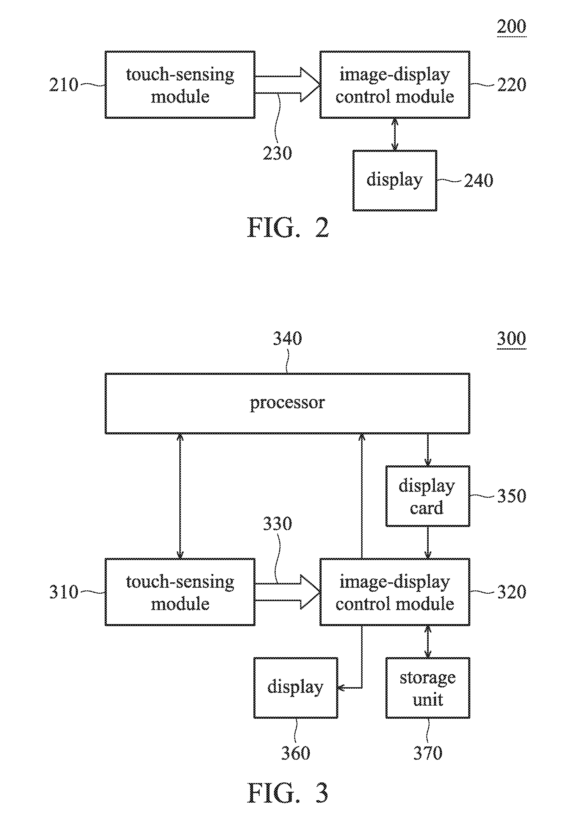
[0018] FIG. 2 is a block diagram of an electronic device 200 in accordance with an embodiment of the present invention. The electronic device 200 can be a touch-sensing display or an electronic blackboard, including a touch-sensing module 210, an image-display control module 220, a channel 230 and a display. The touch-sensing module 210 detects a touch event corresponding to at least one touch object and outputs a position signal corresponding to the touch event. The touch object can be a finger of a user, a touch pen or an object having a conductive element, and the position signal can include a position of a touching point of the touch object and/or position changes of the touch event. The image-display control module 220 is connected to the touch-sensing module 210 via the channel 230 for directly receiving the position signal from the touch-sensing module 240 through the channel 230. The image-display control module 220 enables the display 240 to display a displayed image through a user interface, and after receiving the position signal, the image-display control module 220 further refreshes the entire currently displayed image or at least a portion of the currently displayed image according to the position signal.
[0019] FIG. 3 is a block diagram of the electronic device in accordance with another embodiment of the present invention. As shown in the figure, the electronic device 200 can be any electronic device having a touch-sensing device, and includes a touch-sensing module 310, an image-display control module 320, a channel 330, a processor 340, a display card 350, a display 360 and a storage unit 370. The configuration of touch-sensing module 310, channel 330, and display 360 and the operation to be performed are the same as those of touch-sensing module 210, channel 230 and display 240 described in FIG. 2, and they are not described here to simplify the description. The image-display control module 320 performs different operations for a normal mode and a turbo drawing mode. For example, pixels of the display 360 are refreshed according to the position signal received by the touch-sensing module 310, and/or an image signal output from the display card 350 can be converted into a driving signal for driving the display 360, and the like. The functions performed by the image-display control module 320 can be implemented by a related hardware architecture or program code, or may be implemented by adding the related circuit architecture to a conventional timing controller. The processor 340 executes an application, generates a user interface corresponding to the application, and operates according to various instructions and signals. The display card 350 generates an image signal according to the instructions of the processor 340. The display 360 displays the displayed image according to the drive signal. It should be noted that the touch-sensing module 310 and the image-display control module 320 can be designed on the same wafer or on different wafers according to the needs of the user.
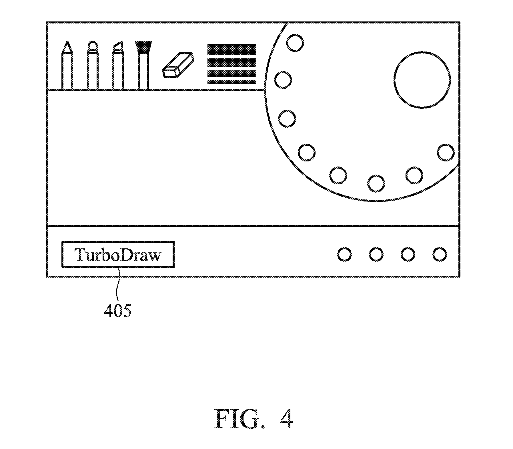
[0020] According to an embodiment of the present invention, when the electronic device 300 operates in the normal mode, after the touch-sensing module 310 detects a touch event (e.g., a click or drag action, etc.) corresponding to the touched object, the touch-sensing module 310 outputs the touch signal corresponding to the touch event to the processor 340. The processor 340 outputs a user interface corresponding to the general display mode according to the performed application, and generates a corresponding image signal through the display card 350. The image-display control module 320 receives the image signal from the display card 350, and converts the image signal into an LVDS signal, a MIPI signal or a panel signal (e.g., an eDP signal) having a high resolution for driving the display 360 to display the displayed image. For example, FIG. 4 is a schematic diagram of the user interface corresponding to the general display mode of a drawing application when the electronic device 300 is operated in the normal mode in accordance with an embodiment of the present invention. As shown in the figure, when the user operates on the user interface, the processor 340 outputs the operation result according to the touch signal, such as enabling different functions according to the position of the touch signal, or displaying a pattern corresponding to a drag action of the touch signal. In the general display mode corresponding to the normal mode, the drawing application can provide a complete drawing function and/or an exquisite background to provide the user with the best visual experience and operation function.
[0021] According to another embodiment of the present invention, when the power state of the system changes (e.g., enters a power saving mode) or the demand for touch screen sensitivity increases, the user can change the signal transmission path of the touch-sensing module 310 through a trigger event to enter the turbo drawing mode. For example, the user can trigger the trigger event by pulling out a stylus, pressing an icon (e.g., icon 405 shown in FIG. 4) on the user interface in the normal mode, or pressing an entity key. When the trigger event occurs, the processor 340 outputs a switching signal to the touch-sensing module 310 and the image-display control module 320 to inform the touch-sensing module 310 and the image-display control module 320 enter to the turbo drawing mode. In the turbo drawing mode, the touch-sensing module 310 stops outputting the touch signal to the processor 340, generates the position signal corresponding to the touch point of the touch event or the drag action (e.g., information about the positions and/or the position changes), and outputs the position signal to the image-display control module 320 through the channel 330. After receiving the position signal, the image-display control module 320 generates a display-image refresh signal based on the received position signal. The display-image refresh signal may be a normal image signal or a pixel refresh signal, a line refresh signal, or a frame refresh signal, etc., which only refreshes the pixels corresponding to position information and/or the pixels adjacent to the position information. Such that the image-display control module 320 can selectively refresh the entire displayed image or only refresh a portion of the current displayed image according to the signal as described above. When the image-display control module 320 selectively only refreshes a portion of the displayed image, the reaction speed corresponding to the touch event of the electronic device 300 can be increased, and the power consumption of the electronic device can be further reduced.
[0022] In addition, when entering the turbo drawing mode, the user interface corresponding to the application in operation can be a simple display mode, and can be provided by the image-display control module 320 to speed up the reaction of the electronic device 300. Comparing with the user interface of the normal display mode, the user interface of the simple display mode has fewer operating functions and/or a simple background. For example, FIG. 5 is a schematic diagram of the user interface corresponding to the simple display mode when the electronic device 300 operates in the turbo drawing mode in accordance with an embodiment of the present invention. As shown in the figure, the user interface shown in FIG. 5 has fewer functions and a simpler background than the functions and the background shown in FIG. 4. In addition, in order to reduce the computation of the image-display control module 320, the user interface of the turbo drawing mode can be presented only in gray-scale or black-and-white, thereby the power consumption of the display or the system can be reduced. The user interface for the turbo drawing mode can be stored in a storage unit 370 (e.g., a memory) connected to the image-display control module 320. Such that when the electronic device 300 enters the turbo drawing mode, the image-display control module 320 can directly download and apply the user interface from the storage unit 370.
[0023] FIG. 6 is a schematic diagram of another user interface of the drawing application operating in the turbo drawing mode in accordance with another embodiment of the present invention. In this embodiment, in order to minimize the power consumption of the system, the background 601 of the user interface is presented in all black and the user interface only supports the most basic functions (such as only the function of a brush and an eraser) and a return icon 605 for returning to the normal mode.
[0024] As described above, the icons shown in FIGS. 4-6 may correspond to different functions, such as color adjustment, thickness adjustment of stroke, image enhancement, image scaling, image distortion, image offset and storing, etc., but it is not limited thereto. When the image-display control module 320 determines that the touch object touches on the icon based on the touch event, the function corresponding to the icon is enabled.
[0025] In addition, according to another embodiment of the present invention, when the image-display control module 320 enters the turbo drawing mode, it is possible to store the last image corresponding to the touch event or each step of actions corresponding to the touch event in the storage unit 370. Furthermore, when the touch-sensing module 310 and the image-display control module 320 switches to the normal mode, the image or action stored in the storage unit 370 is selectively sent back to the processor 340 for further processing.
[0026] According to another embodiment of the present invention, the user may switch the touch-sensing module 310 and the image-display control module 320 back to the normal mode by another trigger event. For example, the user may press another entity key, click on an icon corresponding to a switching function (e.g., the icons 505, 605 shown in FIGS. 5 and 6) or perform a specific gesture on the touch screen for triggering the trigger event. When the image-display control module 320 detects the trigger event based on the touch signal, the image-display control module 320 outputs a wake-up signal to the processor 340 to switch to the normal mode from the turbo drawing mode. In the normal mode, the touch-sensing module 211 outputs the touch signal to the processor 340 when detecting the touch event (e.g., clicking or the drag action, etc.) corresponding to the touch object. In addition, after switching back to the normal mode, the displayed user interface may also switch back to the user interface with more functions provided by the processor 340 (such as the user interface shown in FIG. 4).
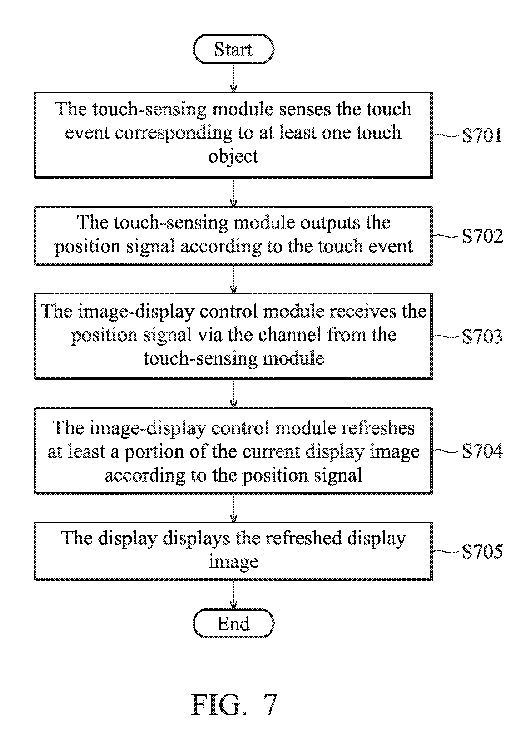
[0027] FIG. 7 is a flowchart of the method for generating a displayed image in accordance with an embodiment of the present invention. In step S701, the touch-sensing module 210 senses the touch event corresponding to at least one touch object. In step S702, the touch-sensing module 210 outputs the position signal according to the touch event. In step S703, the image-display control module 220 receives the position signal via the channel 230 from the touch-sensing module 210. In step S704, the image-display control module 220 refreshes at least a part of the current displayed image according to the position signal. In step S705, the display 240 displays the refreshed displayed image.
[0028] FIG. 8 is a flowchart showing the method for generating a displayed image in accordance with another embodiment of the present invention. In step S801, the user triggers a triggering event (e.g., pulling out the stylus, pressing the icon on the user interface, or pressing the physical key) to enable the touch-sensing module 310 and the image-display control module 320 to receive the switching signal. In step S802, the touch-sensing module 310 and the image-display control module 320 are switched from the normal mode to the turbo drawing mode according to the switching signal. In step S803, the touch-sensing module 310 outputs the position signal according to the touch event of the touch object. In step S804, the touch-sensing module 310 outputs the position signal to the image-display control module 320 via the channel. In step S805, the image-display control module 320 generates the image signal based on the position signal. In step S806, the image-display control module 212 refreshes at least a part of the current displayed image according to the image signal. In step S807, the display 360 displays the refreshed displayed image.
[0029] As described above, according to the electronic device and the method for generating displayed image provided in the present invention, when the electronic device enters the turbo drawing mode, since the touch signal does not need to be processed step by step via the processor and the display card, the reaction speed can be greatly increased to provide a better user experience. In addition, since the processor and the display card do not execute any procedures, the processor and the display card can be disabled or the power status can be changed in the turbo drawing mode. When components other than the touch-sensing module, the image-display control module, and the display are disabled, power savings approach 50%, helping to increase battery life.
[0030] It will be apparent to those skilled in the art that various modifications and variations can be made to the structure disclosed without departing from the scope or spirit of the invention. In view of the foregoing, it is intended that the present invention covers modifications and variations of this invention, provided they fall within the scope of the following claims and their equivalents.
* * * * *
D00000
D00001
D00002
D00003
D00004
D00005
D00006
XML
uspto.report is an independent third-party trademark research tool that is not affiliated, endorsed, or sponsored by the United States Patent and Trademark Office (USPTO) or any other governmental organization. The information provided by uspto.report is based on publicly available data at the time of writing and is intended for informational purposes only.
While we strive to provide accurate and up-to-date information, we do not guarantee the accuracy, completeness, reliability, or suitability of the information displayed on this site. The use of this site is at your own risk. Any reliance you place on such information is therefore strictly at your own risk.
All official trademark data, including owner information, should be verified by visiting the official USPTO website at www.uspto.gov. This site is not intended to replace professional legal advice and should not be used as a substitute for consulting with a legal professional who is knowledgeable about trademark law.