Thermally Conductive Liquid Pack
TANAKA; Ken ; et al.
U.S. patent application number 16/019726 was filed with the patent office on 2019-01-03 for thermally conductive liquid pack. This patent application is currently assigned to KITAGAWA INDUSTRIES CO., LTD.. The applicant listed for this patent is KITAGAWA INDUSTRIES CO., LTD.. Invention is credited to Ken TANAKA, Hideo YUMI.
| Application Number | 20190003787 16/019726 |
| Document ID | / |
| Family ID | 64738021 |
| Filed Date | 2019-01-03 |


| United States Patent Application | 20190003787 |
| Kind Code | A1 |
| TANAKA; Ken ; et al. | January 3, 2019 |
THERMALLY CONDUCTIVE LIQUID PACK
Abstract
Provided is a thermally conductive liquid pack including a liquid thermal conductive material and a hollow pliable outer package filled with the liquid thermal conductive material, the pliable outer package having a first contact surface and a second contact surface different from the first contact surface and being in a closed state, the pliable outer package including a first sheet including the first contact surface, a second sheet including the second contact surface and disposed opposite to the first sheet, the first sheet and the second sheet including a plurality of fine discharge holes capable of discharging the thermal conductive material, a release sheet configured to seal the discharged holes from the outside being releasably layered on the first sheet and the second sheet, and the second sheet including a third sheet formed from a non-woven fabric or mesh in the inside thereof.
| Inventors: | TANAKA; Ken; (Kasugai-shi, JP) ; YUMI; Hideo; (Kasugai-shi, JP) | ||||||||||
| Applicant: |
|
||||||||||
|---|---|---|---|---|---|---|---|---|---|---|---|
| Assignee: | KITAGAWA INDUSTRIES CO.,
LTD. Aichi JP |
||||||||||
| Family ID: | 64738021 | ||||||||||
| Appl. No.: | 16/019726 | ||||||||||
| Filed: | June 27, 2018 |
| Current U.S. Class: | 1/1 |
| Current CPC Class: | F28F 2255/02 20130101; F28F 13/00 20130101; F28F 2275/025 20130101; F28F 2280/00 20130101; F28D 2021/0029 20130101; F28F 2013/006 20130101; F28F 2013/001 20130101; H01L 23/42 20130101 |
| International Class: | F28F 13/00 20060101 F28F013/00 |
Foreign Application Data
| Date | Code | Application Number |
|---|---|---|
| Jun 29, 2017 | JP | 2017-127158 |
Claims
1. A thermally conductive liquid pack comprising: a thermally conductive material in a liquid state; and a hollow pliable outer package, the hollow pliable outer package being filled with the liquid thermal conductive material, wherein the hollow pliable outer package includes a first contact surface and a second contact surface different from the first contact surface and is in a closed state.
2. The thermally conductive liquid pack according to claim 1, wherein the hollow pliable outer package includes a first sheet including the first contact surface, a second sheet including the second contact surface and disposed opposite to the first sheet, and a release sheet, at least one of the first sheet and the second sheet includes a plurality of fine discharge holes capable of discharging the thermal conductive material, and the release sheet is configured to seal the plurality of fine discharged holes from the outside and is releasably layered on the at least one of the first sheet and the second sheet.
3. The thermally conductive liquid pack according to claim 1, wherein the hollow flexible outer package includes a first sheet including the first contact surface, a second sheet including the second contact surface and disposed opposite to the first sheet, and a release sheet, at least one of the first sheet and the second sheet is formed from a non-woven fabric or a mesh, and the release sheet is configured to suppress leakage of the thermal conductive material from the outside and is releasably layered on the non-woven fabric or mesh.
4. The thermally conductive liquid pack according to claim 1, wherein the hollow pliable outer package includes a first sheet including the first contact surface, a second sheet including the second contact surface and disposed opposite to the first sheet, and a release sheet, the first sheet and the second sheet include a plurality of fine discharge holes capable of discharging the thermal conductive material, the release sheet is configured to seal the plurality of fine discharged holes from the outside and is releasably layered on the first sheet and the second sheet, and the second sheet includes a third sheet formed from a non-woven fabric or a mesh in the inside thereof.
5. The thermally conductive liquid pack according to claim 4, wherein the plurality of discharge holes in the first sheet have a hole diameter larger than a hole diameter of the plurality of discharge holes in the second sheet.
6. The thermally conductive liquid pack according to claim 2, wherein the thermal conductive material has adhesiveness.
7. The thermally conductive liquid pack according to claim 3, wherein the thermal conductive material has adhesiveness.
8. The thermally conductive liquid pack according to claim 4, wherein the thermal conductive material has adhesiveness.
9. The thermally conductive liquid pack according to claim 5, wherein the thermal conductive material has adhesiveness.
10. The thermally conductive liquid pack according to claim 2, wherein the hollow pliable outer package includes a first sheet including the first contact surface, a second sheet including the second contact surface and disposed opposite to the first sheet, and a release sheet, at least one of the first sheet and the second sheet is formed from a non-woven fabric or a mesh, and the release sheet is configured to suppress leakage of the thermal conductive material from the outside and is releasably layered on the non-woven fabric or mesh.
11. The thermally conductive liquid pack according to claim 10, wherein the thermal conductive material has adhesiveness.
Description
CROSS-REFERENCE TO RELATED APPLICATIONS
[0001] This application claims the benefit of Japanese Patent Application No. 2017-127158 filed Jun. 29, 2017 in the Japan Patent Office, and the entire disclosure of Japanese Patent Application No. 2017-127158 is incorporated herein by reference.
BACKGROUND
[0002] The present invention relates to a thermally conductive liquid pack.
[0003] In the related art, a thermally conductive sheet is often used as a thermally conductive member provided so as to fill a gap between electronic components disposed on a substrate and a heat dissipation member disposed on a side opposite to the substrate among the electronic components. The thermally conductive sheet has advantages such as easy handling property. In a case of a thermally conductive sheet having elasticity, the thermally conductive sheet can be brought into close contact with the electronic components and the heat dissipation member.
[0004] However, it is difficult that the thermally conductive sheet is brought into close contact with a plurality of electronic components having different heights from the substrate together. Therefore, the size and thickness of the thermally conductive sheet need to be changed depending on portions (electronic components) where the thermally conductive sheet is used.
[0005] Accordingly, putty or grease may be used as the thermally conductive member. In this case, the amount of putty or grease to be used can be adjusted and the putty or grease is allowed to come into close contact with a complex structure to which the thermally conductive sheet is not applicable and to fill a gap.
CITATION LIST
Patent Literature
[0006] Patent Literature 1: JP 2016-062953 A
[0007] Patent Literature 2: JP 2016-143634 A
SUMMARY
[0008] However, when the viscosity of putty or grease is decreased so as to be applied to the complex structure, the putty or grease may flow down from use portions. As the temperature increases, the viscosity of putty or grease generally decreases. Therefore, when putty or grease having relatively high viscosity is tried to be applied in consideration of decrease in viscosity, the putty or grease cannot be applied to a fine structure and the adhesion may be decreased.
[0009] When the amount of putty or grease to be used is smaller or larger than a proper amount, troubles such as insufficient adhesion and entrapment of air occur. Therefore, control of the use amount is required and improvement of workability is desired.
[0010] In the circumstances, the present invention has been completed. An object of the present invention is to provide a thermally conductive liquid pack as a thermally conductive member that is applicable to a complex structure and has excellent heat transfer and workability.
[0011] The present invention provides a thermally conductive liquid pack including a liquid thermally conductive material and a hollow pliable outer package filled with the liquid thermally conductive material. The hollow pliable outer package includes a first contact surface and a second contact surface different from the first contact surface and is in a closed state.
[0012] According to the present invention, the thermally conductive liquid pack can be freely deformed due to the pliable outer package that is flexible and the liquid thermally conductive material placed in the pliable outer package. Therefore, even when a heating body and a heat dissipation body have a complex shape, the first contact surface and the second contact surface can be easily deformed along the complex shape and come into close contact with the heating body and the heat dissipation body by pressing the thermally conductive liquid pack against the heating body and the heat dissipation body.
[0013] Further, even when the temperature of a setting environment and the heating body increases, the thermally conductive liquid pack does not flow down, unlike grease and putty. Therefore, the thermally conductive liquid pack can be in close contact with an adherend and keep favorable heat transfer. Since the thermally conductive liquid pack has a pack shape, control of use amount is not necessary, the thermally conductive liquid pack is only arranged at a setting portion, and the thermally conductive liquid pack has excellent workability, unlike putty and grease.
[0014] A liquid includes a substance having such a viscosity that the shape is hardly held by itself like honey, and represents a so-called viscous body.
[0015] The thermally conductive liquid pack may include a configuration described below.
[0016] The pliable outer package includes a first sheet including the first contact surface and a second sheet including the second contact surface and disposed opposite to the first sheet, at least one of the first sheet and the second sheet includes a plurality of fine discharge holes capable of discharging the thermally conductive material, and a release sheet configured to seal the discharged holes from the outside is releasably layered on the at least one of the first sheet and the second sheet.
[0017] With the configuration, during using the thermally conductive liquid pack, the release sheet is peeled and the first contact surface of the first sheet and/or the second contact surface of the second sheet is pressed against an adherend. The thermally conductive material is gradually discharged through the discharge holes and spreads between the first contact surface and/or the second contact surface and the adherend. Thus, the thermally conductive liquid pack (the pliable outer package and the thermally conductive material) reliably comes into close contact with the adherend. Further, the thermally conductive liquid pack is unlikely to slip from the adherend due to the viscosity and surface tension of the spread thermally conductive material. When the thermally conductive material has adhesiveness, the thermally conductive liquid pack is fixed on the adherend.
[0018] Further, the pliable outer package includes a first sheet including the first contact surface and a second sheet including the second contact surface and disposed opposite to the first sheet, at least one of the first sheet and the second sheet is formed from a non-woven fabric or mesh, and a release sheet configured to suppress discharge of the thermally conductive material from the outside is releasably layered on the non-woven fabric or mesh.
[0019] With the configuration, during use of the thermally conductive liquid pack, the release sheet is peeled and the first contact surface of the first sheet and/or the second contact surface of the second sheet is pressed against an adherend. The thermally conductive material gradually oozes through the non-woven fabric or mesh and spreads between the first contact surface and/or the second contact surface and the adherend. Thus, the thermally conductive liquid pack (the pliable outer package and the thermally conductive material) reliably comes into close contact with the adherend. Further, the thermally conductive liquid pack is unlikely to slip from the adherend due to the viscosity and surface tension of the spread thermally conductive material. When the thermally conductive material has adhesiveness, the thermally conductive liquid pack is fixed on the adherend.
[0020] Furthermore, the pliable outer package includes a first sheet including the first contact surface and a second sheet including the second contact surface and disposed opposite to the first sheet, the first sheet and the second sheet include a plurality of fine discharge holes capable of discharging the thermally conductive material, a release sheet configured to seal the plurality of discharged holes from the outside is releasably layered on the first sheet and the second sheet, and a third sheet formed from a non-woven fabric or mesh is layered on an internal surface of the second sheet.
[0021] With the configuration, the timing of discharge, discharge rate, and discharge amount of the thermally conductive material on a side of the first sheet, the timing of discharge, discharge rate, and discharge amount of the thermally conductive material on a side of the second sheet can be controlled so as to be different from each other. Specifically, on the first sheet side, the thermally conductive material leaks directly from the inside of the pliable outer package, and on the second sheet side, the thermally conductive material oozes from the inside of the pliable outer package to the third sheet (the non-woven fabric or mesh) and then oozes out through the discharge holes of the second sheet. Therefore, the first sheet may be pressed against the adherend by pressing from the second sheet side, to come into close contact with the adherend. Then, the adherend may be pressed against the second sheet to come into close contact with the second sheet. At that time, the thermally conductive material does not leak to the second sheet side under pressing from the second sheet side. Therefore, a hand and a tool for pressing are not made dirty.
[0022] When the hole diameter of the discharge holes in the first sheet is set to be larger than the hole diameter of the discharge holes in the second sheet, the discharge rate and discharge amount of the thermally conductive material on the first sheet side and the discharge rate and discharge amount of the thermally conductive material on the second sheet side are more easily controlled so as to be different from each other.
[0023] When the thermally conductive liquid pack is configured to discharge the thermally conductive material, it is preferable that the thermally conductive material have such a viscosity that the thermally conductive material does not easily drip, unlike water.
[0024] The thermally conductive material may have adhesiveness. With such a configuration, the thermally conductive material leaked from the pliable outer package causes the thermally conductive liquid pack to adhere to the adherend.
[0025] According to the present invention, a thermally conductive liquid pack that is applicable to a complex structure (shape) and has excellent heat transfer and workability is obtained.
BRIEF DESCRIPTION OF THE DRAWINGS
[0026] The invention will be described with reference to the accompanying drawings, wherein like numbers reference like elements.
[0027] FIG. 1 is a cross-sectional view of a thermally conductive liquid pack in the first embodiment.
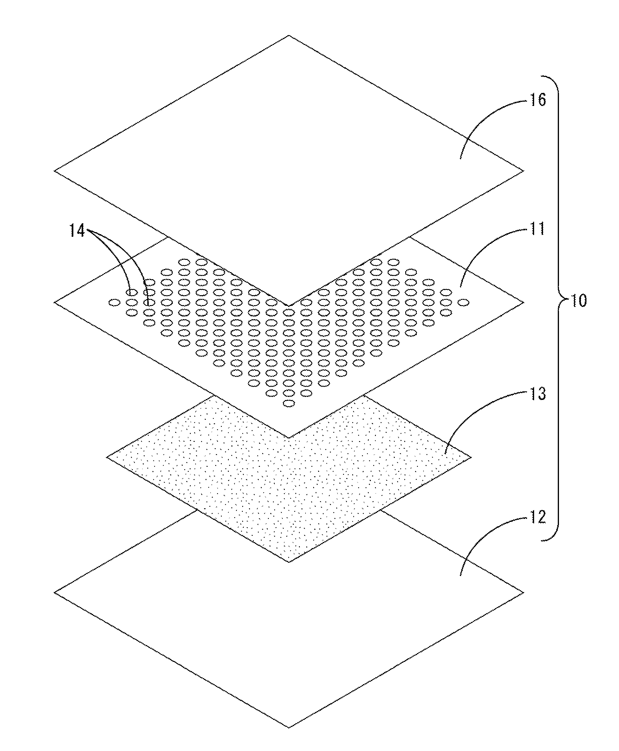
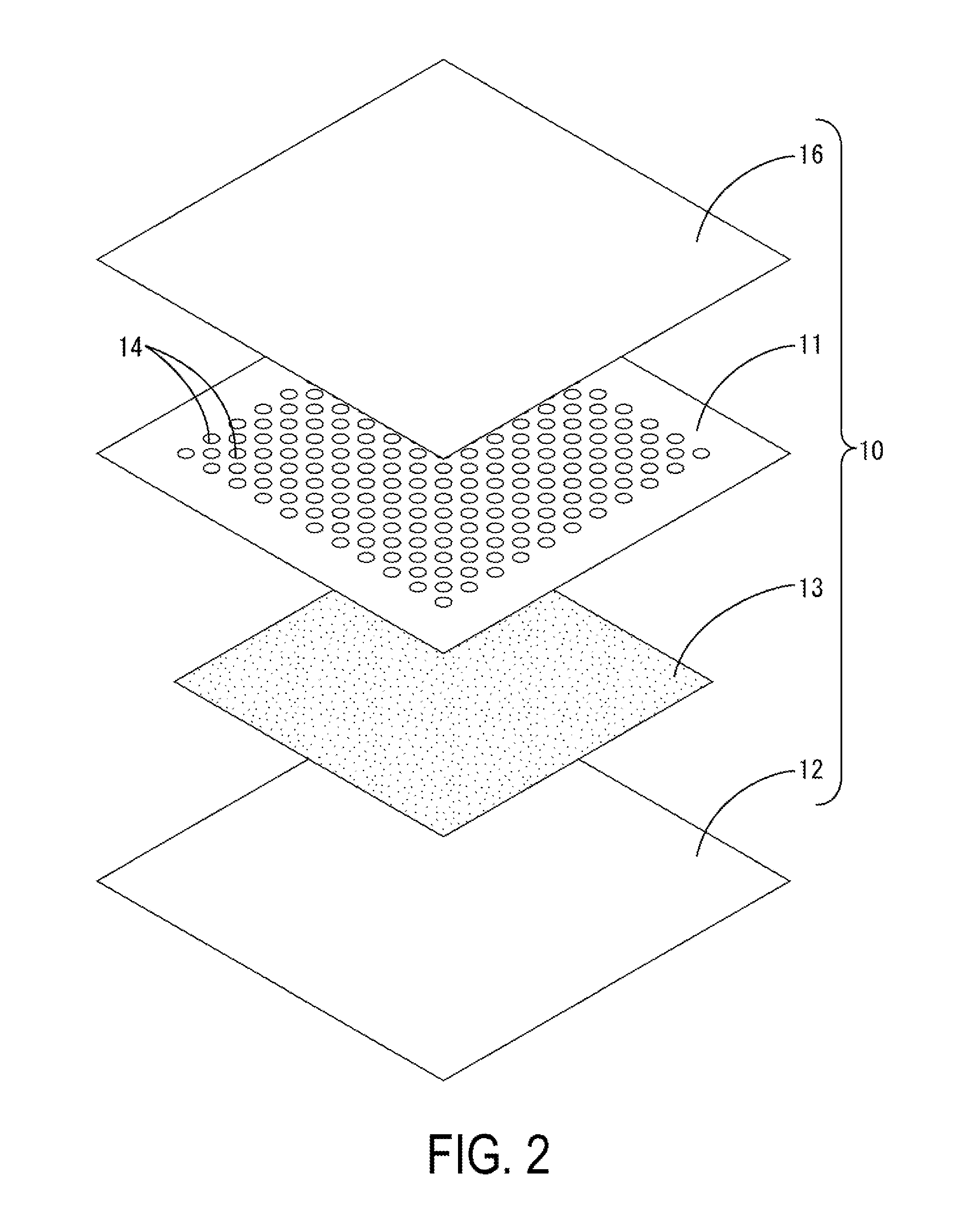
[0028] FIG. 2 is an exploded perspective view of the thermally conductive liquid pack.
[0029] FIG. 3 is a cross-sectional view illustrating a use state of the thermally conductive liquid pack.
[0030] FIG. 4 is a cross-sectional view of a thermally conductive liquid pack in the second embodiment.
[0031] FIG. 5 is an exploded perspective view of a thermally conductive liquid pack in the third embodiment.
[0032] FIG. 6 is a cross-sectional view of the thermally conductive liquid pack.
DESCRIPTION OF EMBODIMENTS
First Embodiment
[0033] The first embodiment will be described with reference to FIGS. 1 to 3. In a thermally conductive liquid pack 10 of this embodiment, a hollow outer package (an example of a pliable outer package) in which edges of a pair of rectangular sheets (a first sheet 11 and a second sheet 12), are closed by thermal welding is filled with a liquid thermally conductive material 13.
[0034] The first sheet 11 and the second sheet 12 are formed from a pliable resin that is flexible, such as an HS-PET film with a side of 15 mm (heat resistance temperature: 125.degree. C. or higher). The thickness of the first sheet 11 and the second sheet 12 is set within a range from 27 to 52 .mu.m (in this embodiment, 32 .mu.m). In the first sheet 11 of the pair of sheets, a plurality of circular discharge holes 14 with a diameter of 1.5 mm are uniformly provided at an interval of 4.0 mm over the entire surface.
[0035] On an external surface 11A of the first sheet 11, a release sheet 16 that is releasable is layered. The plurality of discharge holes 14 are sealed with the release sheet 16.
[0036] For example, the thermally conductive material 13 is a substance in which a thermally conductive filler and an additive are mixed in an acrylic resin. The thermally conductive material 13 is a liquid having such a low viscosity that the shape is hardly held by itself like honey. The thermally conductive material 13 has such a viscosity that the thermally conductive material does not easily drip, unlike water. Further, the thermally conductive material 13 has adhesiveness. The thermally conductive material 13 can be filled between the first sheet 11 and the second sheet 12 by mixing raw materials and sucking up the raw materials by using a vertical pillow packaging device (liquid and paste packaging machine MR-8 manufactured by SANKO MACHINERY CO., LTD).
[0037] In FIG. 2, the thermally conductive material 13 is illustrated as a solid for convenience. Before use, the thermally conductive material 13 hardly enters the inside of fine discharge holes 14 and has such a viscosity that the thermally conductive material is held between the first sheet 11 and the second sheet 12 (see FIG. 1).
[0038] During using the thermally conductive liquid pack 10 of the embodiment, the release sheet 16 is peeled to expose the external surface 11A (an example of a first contact surface) of the first sheet 11. The exposed external surface 11A is faced to an adherend C and then pressed against the adherend C from the second sheet 12 side.
[0039] As a result, the thermally conductive material 13 filled in the thermally conductive liquid pack 10 enters the discharge holes 14, leaks to the outside, and then spreads between the external surface 11A (the first contact surface) and the adherend C, as illustrated in FIG. 3. Thus, the thermally conductive liquid pack 10 is brought into close contact with the adherend C in a state where slipping hardly occurs due to the viscosity and surface tension of the spread thermally conductive material 13. Subsequently, the thermally conductive liquid pack 10 is dried to be adhered to the adherend C. As the thermally conductive material 13, a thermally conductive material having adhesiveness without drying may be used.
[0040] The thermally conductive liquid pack 10 in this embodiment can be freely deformed due to the first sheet 11 and the second sheet 12 that are flexible and pliable and the liquid thermally conductive material 13 filled in the thermally conductive liquid pack 10. Therefore, even when the adherend C has a complex shape, the thermally conductive liquid pack 10 can be easily deformed along the complex shape and come into close contact with the adherend C by pressing the thermally conductive liquid pack 10 against the adherend C. Even when a gap between the thermally conductive liquid pack 10 and the adherend C is large, the liquid thermally conductive material does not flow down during use of the liquid thermally conductive material.
[0041] Further, the first sheet 11 has the plurality of fine discharge holes 14, and the thermally conductive material 13 filled in the inside leaks to the external surface 11A of the first sheet 11. Therefore, the thermally conductive material 13 can be brought into contact with a finer portion. In addition, slipping of the thermally conductive liquid pack 10 from the adherend can be suppressed due to the viscosity and surface tension of the thermally conductive material 13 until the thermally conductive material is adhered by drying.
[0042] Even when the temperature of a setting environment and the adherend C increases, the thermally conductive liquid pack 10 does not flow down, unlike grease and putty. Therefore, the thermally conductive liquid pack 10 can be in close contact with the adherend C and keep favorable heat transfer. Since the thermally conductive liquid pack 10 has a pack shape, the thermally conductive liquid pack is only arranged at a setting portion in an assembly line without a liquid quantitative dispenser, and the thermally conductive liquid pack has excellent workability.
Second Embodiment
[0043] The second embodiment will be described with reference to FIG. 4. Hereinafter, only a configuration different from that of the first embodiment will be described. For the same component as that in the first embodiment, a number in which 10 is added to the number of each component in the first embodiment is used.
[0044] In a thermally conductive liquid pack 20 of this embodiment, a second sheet 22 is formed from a polyester non-woven fabric instead of an HS-PET film, differently from the first embodiment. In this embodiment, the non-woven fabric with a fabric weight of 50 g/m2 is used.
[0045] Edges of a first sheet 21 and the second sheet 22 are closed by heat welding and the inside thereof is filled with a thermally conductive material 23. On an external surface 22A of the second sheet 22, a release sheet 27 that is releasable is layered. Before use, the thermally conductive material 23 almost has such a viscosity that the thermally conductive material 23 is held between the first sheet 21 and the second sheet 22 (the non-woven fabric) although the thermally conductive material 23 partially oozes to the second sheet 22 (the non-woven fabric).
[0046] During use of the thermally conductive liquid pack 20 of the embodiment, the release sheet 27 is peeled to expose the external surface 22A (an example of a second contact surface) of the second sheet 22. The external surface 22A is faced to an adherend and then pressed against the adherend from the first sheet 21 side.
[0047] As a result, the thermally conductive material 23 filled in the thermally conductive liquid pack 20 oozes to the second sheet 22 (the non-woven fabric), gradually oozes out to the external surface 22A, and then gradually spreads between the external surface 22A (the second contact surface) and the adherend. Thus, the thermally conductive liquid pack 20 is brought into close contact with the adherend in a state where slipping hardly occurs due to the viscosity and surface tension of the spread thermally conductive material 23. Subsequently, the thermally conductive liquid pack 20 is dried to be adhered to the adherend.
[0048] The thermally conductive liquid pack 20 of this embodiment is also applicable to a complex structure and has excellent heat transfer and workability, like the first embodiment.
Third Embodiment
[0049] Next, the third embodiment will be described with reference to FIGS. 5 and 6. Hereinafter, only a configuration different from that of the first embodiment will be described. For the same component as that in the first embodiment, a number in which 20 is added to the number of each component in the first embodiment is used.
[0050] In a thermally conductive liquid pack 30 of this embodiment, a hollow outer package (an example of a pliable outer package) in which edges of a pair of rectangular sheets (a first sheet 31 and a second sheet 32), are closed by thermal welding is filled with a liquid thermally conductive material 33. The thermally conductive material 33 has adhesiveness.
[0051] In the first sheet 31, a plurality of first circular discharge holes 34 with a diameter of 1.5 mm are uniformly provided at an interval of 5.0 mm over the entire surface. In the second sheet 32, a plurality of second circular discharge holes 35 with a diameter of 1.0 mm are uniformly provided at an interval of 5.0 mm over the entire surface. That is, the hole diameter of the first discharge holes 34 is larger than the hole diameter of the second discharge holes 35.
[0052] On an external surface 31A (a first contact surface) of the first sheet 31, a first release sheet 36 that is releasable is layered. On an external surface 32A (a second contact surface) of the second sheet 32, a first release sheet 37 that is releasable is layered similarly. The plurality of discharge holes 34 and 35 are sealed with the release sheets 36 and 37.
[0053] On an internal surface (a surface on a side opposite to the second contact surface) of the second sheet 32, a third sheet 38 formed from a mesh is layered through an adhesive not illustrated in the drawing. The thermally conductive material 33 is filled between the first sheet 31 and the third sheet 38. Before use, the thermally conductive material 33 almost has such a viscosity that the thermally conductive material 33 is held between the first sheet 31 and the third sheet 38 although the thermally conductive material 33 partially oozes to the third sheet 38 (the mesh). In FIG. 6, the thermally conductive material 33 is illustrated as a solid for convenience.
[0054] During use of the thermally conductive liquid pack 30 of the embodiment, the first release sheet 36 is peeled to expose the external surface 31A (an example of the first contact surface) of the first sheet 31, and the second release sheet 37 is peeled to expose the external surface 32A (an example of the second contact surface) of the second sheet 32. The external surface 31A is faced to an adherend and then pressed against the adherend from the second sheet 32 side.
[0055] As a result, the thermally conductive material 33 filled in the thermally conductive liquid pack 30 leaks through the discharge holes 34 of the first sheet 31 and gradually spreads between the external surface 31A and the adherend. At that time, the thermally conductive material 33 oozes to the third sheet 38 (mesh) on a pressing side (the second contact surface side). The thermally conductive material 33 does not leak to the outside (the external surface 32A).
[0056] Subsequently, another adherend is disposed on the second sheet 32 side and then pressed against the first sheet 31. After a while, the thermally conductive material 33 oozed to the third sheet 38 (the mesh) reaches the second discharge holes 35, leaks through the second discharge holes 35, and gradually spreads between the external surface 32A (the second contact surface) and the adherend.
[0057] According to this embodiment, the timing of discharge of the thermally conductive material 33 on the first sheet 31 side (the external surface 31A) and the timing of discharge of the thermally conductive material 33 on the second sheet 32 side (the external surface 32A) can be controlled so as to be different from each other.
[0058] That is, on the first sheet 31 side, the thermally conductive material 33 leaks directly through the first discharge holes 34, and on the second sheet 32 side, the thermally conductive material 33 oozes out from the third sheet 38 (the mesh) and then leaks through the second discharge holes 35 of the second sheet 32.
[0059] Therefore, when the external surface 31A of the first sheet 31 is pressed against the adherend by pressing from the second sheet 32 side and comes into close contact with the adherend, the thermally conductive material 33 does not leak to the second sheet side 32. Accordingly, a hand and a tool for pressing is not made dirty. After then, the external surface 32A of the second sheet 32 may be pressed against the adherend to bring the thermally conductive material 33 leaked later into close contact with the second sheet 32.
[0060] When the thermally conductive material 33 oozes out to the third sheet 38 (the mesh) and then leaks through the second discharge holes 35, discharge of the thermally conductive material 33 through the first discharge holes 34 gradually proceeds. That is, the discharge amount of the thermally conductive material 33 through the first discharge holes 34 is larger than the discharge amount of the thermally conductive material 33 through the second discharge holes 35. Therefore, when the first sheet 31 is disposed on a side having an uneven surface that requires a larger amount of the thermally conductive material 33, such as a substrate side, and the second sheet 32 is disposed on a side having a flat surface such as a heat dissipation plate, the first sheet 31 and the second sheet 32 can be each brought into close contact with a proper amount of the thermally conductive material 33.
[0061] The thermally conductive material 33 leaks directly through the first discharge holes 34, but the thermally conductive material 33 only leaks in an amount of the thermally conductive material 33 that oozes out from the third sheet 38 through the second discharge holes 35. Therefore, the discharge rate of the thermally conductive material 33 through the first discharge holes 34 is different from the discharge rate of the thermally conductive material 33 through the second discharge holes 35.
[0062] Since the hole diameter of the first discharge holes 34 is set to be larger than hole diameter of the second discharge holes 35, the discharge rate of the thermally conductive material 33 on the first sheet 31 side is different from the discharge rate of the thermally conductive material 33 on the second sheet 32 side. Therefore, the discharge amount of the thermally conductive material 33 from the first discharge holes 34 is larger than the discharge amount of the thermally conductive material 33 from the second discharge holes 35.
[0063] According to this embodiment, the thermally conductive liquid pack 30 that is applicable to a complex structure and has excellent heat transfer and workability is obtained.
Other Embodiments
[0064] The present invention is not limited by the preceding recitations and/or the embodiments described using the drawings, and various aspects such as the following should be construed to be included in the scope of the technology disclosed in the present invention.
[0065] The aforementioned embodiments represent that a thermally conductive liquid is discharged between a thermally conductive liquid pack and an adherend by providing discharge holes in the thermally conductive liquid pack or providing a non-woven fabric or mesh in the thermally conductive liquid pack. However, the thermally conductive liquid may not necessarily be discharged to the outside. Further, the thermally conductive liquid pack may be configured to come into close contact with the adherend with closing. In this case, it is preferable that the pliable outer package be filled with the thermally conductive material without a space.
[0066] In the embodiments, the outer package is formed by welding or adhering edges of the pair of rectangular sheets (the first sheet and the second sheet). However, the outer package may have a configuration in which a sheet is folded into two to form first and second sheets and overlapped edges of the first and second sheets are welded or adhered.
[0067] A thermally conductive liquid pack in a complete form is not limited to the aforementioned embodiments and may be appropriately modified according to the form of an adherend and a setting position. For example, the thermally conductive liquid pack may have a polyhedral form in which a plurality of sheets are jointed or a gored form applicable to a largely uneven form (with large thickness).
[0068] The first and second embodiments represent the thermally conductive liquid pack in which the thermally conductive material leaks only to one surface. However, the thermally conductive liquid pack may have a configuration in which the thermally conductive material leaks to both surfaces. Alternatively, the thermally conductive liquid pack may have a configuration in which discharge holes are provided on one surface side and a non-woven fabric or mesh is provided on another surface side.
[0069] In the third embodiment, a thermally conductive liquid pack in which the hole diameters of discharge holes on both sides are the same as each other and the discharge amounts on the both sides are made different from each other only by effects of the mesh or non-woven fabric can be formed.
[0070] The hole diameter and shape of the discharge holes and the opening of the non-woven fabric or mesh are not limited to the aforementioned embodiments, and may be appropriately modified. The positions where the discharge holes are set are not limited to the entire surface of the sheet, and may be provided on a part of the surface.
[0071] In the aforementioned embodiments, the thermally conductive material may be configured to have such a viscosity that the thermally conductive material does not enter the discharge holes or ooze out to the non-woven fabric or mesh before using the thermally conductive liquid pack. However, a liquid thermally conductive material having low viscosity such as water may be used. In this case, the thermally conductive material may be configured to enter the discharge holes or a part or the whole of the non-woven fabric or mesh before using the thermally conductive liquid pack.
[0072] The thermal conductive material may not necessarily have adhesiveness.
[0073] The second embodiment represents the configuration of the pliable outer package in which the edge of the second sheet 22 (the non-woven fabric) and the first sheet 21 are closed by thermal welding. However, the pliable outer package in a closed state may be formed by thermally welding the edge of the release sheet 27 in which the second sheet 22 is layered in the inside thereof with the first sheet 21.
* * * * *
D00000
D00001
D00002
D00003
D00004
D00005
D00006
XML
uspto.report is an independent third-party trademark research tool that is not affiliated, endorsed, or sponsored by the United States Patent and Trademark Office (USPTO) or any other governmental organization. The information provided by uspto.report is based on publicly available data at the time of writing and is intended for informational purposes only.
While we strive to provide accurate and up-to-date information, we do not guarantee the accuracy, completeness, reliability, or suitability of the information displayed on this site. The use of this site is at your own risk. Any reliance you place on such information is therefore strictly at your own risk.
All official trademark data, including owner information, should be verified by visiting the official USPTO website at www.uspto.gov. This site is not intended to replace professional legal advice and should not be used as a substitute for consulting with a legal professional who is knowledgeable about trademark law.