Workpiece Polishing Apparatus
HASHIMOTO; Hiromasa ; et al.
U.S. patent application number 16/123383 was filed with the patent office on 2019-01-03 for workpiece polishing apparatus. This patent application is currently assigned to SHIN-ETSU HANDOTAI CO., LTD.. The applicant listed for this patent is SHIN-ETSU HANDOTAI CO., LTD.. Invention is credited to Hiromasa HASHIMOTO, Masanao SASAKI.
| Application Number | 20190001463 16/123383 |
| Document ID | / |
| Family ID | 64735186 |
| Filed Date | 2019-01-03 |


| United States Patent Application | 20190001463 |
| Kind Code | A1 |
| HASHIMOTO; Hiromasa ; et al. | January 3, 2019 |
WORKPIECE POLISHING APPARATUS
Abstract
A workpiece polishing apparatus including a polishing pad to polish a workpiece, a polishing agent supplying mechanism to supply a polishing agent, and a polishing head to hold the workpiece such that a back surface of the workpiece is held by a backing pad and an edge of the workpiece is held by an annular template. This apparatus polishes the workpiece by pressing the workpiece and the template against the polishing pad and thereby bringing the workpiece into sliding contact with the polishing pad. The template is made of a resin containing filler or woven fabric and has fine depressions created by filler or woven fabric exposed on the surface on the side that presses the polishing pad. This apparatus can stabilize the polishing rate of the outer circumferential portion of the workpiece and thereby polish the workpiece into a very flat workpiece.
| Inventors: | HASHIMOTO; Hiromasa; (Nishigo-mura, JP) ; SASAKI; Masanao; (Nishigo-mura, JP) | ||||||||||
| Applicant: |
|
||||||||||
|---|---|---|---|---|---|---|---|---|---|---|---|
| Assignee: | SHIN-ETSU HANDOTAI CO.,
LTD. Tokyo JP |
||||||||||
| Family ID: | 64735186 | ||||||||||
| Appl. No.: | 16/123383 | ||||||||||
| Filed: | September 6, 2018 |
Related U.S. Patent Documents
| Application Number | Filing Date | Patent Number | ||
|---|---|---|---|---|
| 14787659 | Oct 28, 2015 | |||
| PCT/JP2014/002066 | Apr 10, 2014 | |||
| 16123383 | ||||
| Current U.S. Class: | 1/1 |
| Current CPC Class: | B24B 37/20 20130101; B24B 37/32 20130101 |
| International Class: | B24B 37/20 20060101 B24B037/20; B24B 37/32 20060101 B24B037/32 |
Foreign Application Data
| Date | Code | Application Number |
|---|---|---|
| May 16, 2013 | JP | 2013-103719 |
Claims
1. A workpiece polishing apparatus comprising: a polishing pad configured to polish a workpiece; a polishing agent supplying mechanism configured to supply a polishing agent; and a polishing head including a backing pad and an annular template configured to hold the workpiece such that a back surface of the workpiece is held by the backing pad and an edge of the workpiece is held by the template; the apparatus being configured to polish the workpiece by pressing the workpiece and the template against the polishing pad and thereby bringing the workpiece into sliding contact with the polishing pad, wherein the template is made of a resin containing filler and has fine depressions on a surface on a side that presses the polishing pad, the fine depressions being created by the filler exposed on the surface on the side that presses the polishing pad, and a surface coverage of the depressions on the surface of the template on the side that presses the polishing pad ranges from 5% to 85%.
2. The workpiece polishing apparatus according to claim 1, wherein each of the depressions has a depth of 0.05 mm or more.
3. The workpiece polishing apparatus according to claim 1, wherein each of the depressions has an opening with a width of 5 mm or less, and pitches among the depressions are 10 mm or less.
4. The workpiece polishing apparatus according to claim 2, wherein each of the depressions has an opening with a width of 5 mm or less, and pitches among the depressions are 10 mm or less.
5. The workpiece polishing apparatus according to claim 1, wherein a contact angle between each of the depressions and the polishing pad is 90.degree. or less.
6. The workpiece polishing apparatus according to claim 2, wherein a contact angle between each of the depressions and the polishing pad is 90.degree. or less.
7. The workpiece polishing apparatus according to claim 3, wherein a contact angle between each of the depressions and the polishing pad is 90.degree. or less.
8. The workpiece polishing apparatus according to claim 4, wherein a contact angle between each of the depressions and the polishing pad is 90.degree. or less.
9. The workpiece polishing apparatus according to claim 1, wherein the surface coverage of the depressions on the surface of the template on the side that presses the polishing pad is more than 25% and 85% or less.
Description
[0001] This is a Continuation-in-Part of application Ser. No. 14/787,659 filed Oct. 28, 2015, which is a National Stage Entry of PCT/JP2014/002066 filed Apr. 10, 2014, which claims priority to JP 2013-103719 filed May 16, 2013. The disclosure of the prior applications is hereby incorporated by reference herein in its entirety.
TECHNICAL FIELD
[0002] The present invention relates to a workpiece polishing apparatus.
BACKGROUND ART
[0003] In production of semiconductor wafers such as silicon wafers, a polishing process to improve surface roughness and flatness of a wafer is one of important processes.
[0004] As the precision of devices has recently been increased, there is an increasing need for more precisely flattened semiconductor wafers for use in device fabrication. According to this need, chemical mechanical polishing (CMP) is used as a technique to flatten a surface of semiconductor wafers.
[0005] Apparatuses for polishing surfaces of a wafer such as a silicon wafer may be classified into two types: a single-side polishing apparatus that polishes one side of a workpiece at a time and a double-side polishing apparatus that polishes both sides simultaneously.
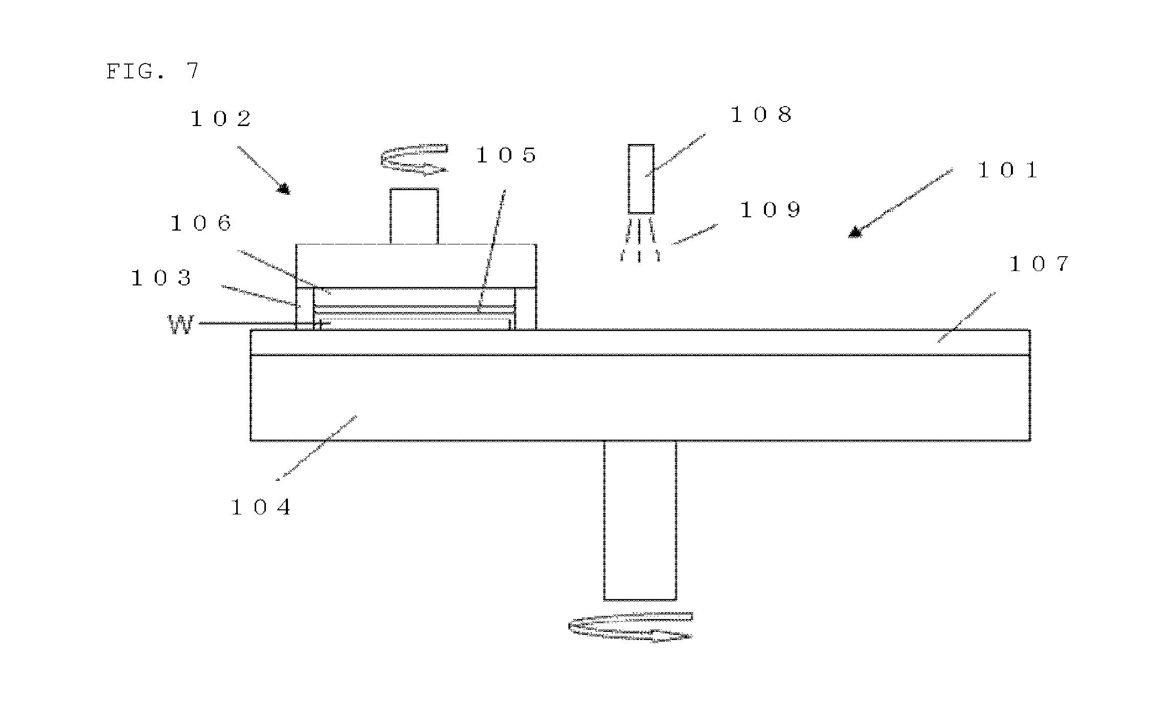
[0006] As shown in FIG. 7, for example, a common single-side polishing apparatus is constituted of a turn table 104 to which a polishing pad 107 is attached, a polishing agent supplying mechanism 108, a polishing head 102, and other components. The polishing apparatus 101 of this type holds a workpiece W by the polishing head 102, supplies a polishing agent 109 to the polishing pad 107 through the polishing agent supplying mechanism 108, rotates the turn table 104 and the polishing head 102, and bring a surface of the workpiece W into sliding contact with the polishing pad 107 to polish the workpiece W.
[0007] There are plural methods to hold a workpiece, such as a method of attaching the workpiece to a flat disc-like plate by an adhesive such as wax, a method of attaching the workpiece to a soft pad (a baking material) by water, and a method of attaching the workpiece by vacuum suction.
[0008] In the polishing head 102 shown in FIG. 7, an elastic pad (a baking pad) 105 such as a polyurethane pad is stack on the lower surface of a disc-like holding plate 106 made of, for example, ceramics. The workpiece W is held by a surface tension of wafer absorbed by this elastic pad 105. A guide ring 103 to prevent the workpiece W from coming off the holding plate 106 during polishing is also provided around the holding plate 106.
[0009] This polishing apparatus 101 is easily affected by the precision of the flatness of the holding plate 106, variation in dimension due to deformation occurring when a pressure is applied to the holding plate 106, and the precision of the thickness of the backing pad 105, because the polishing apparatus 101 indirectly presses the workpiece W through the holding plate 106. It is difficult to polish the entire surface of the workpiece with very high precision. In addition, an outer circumferential portion of the workpiece tends to be polished in a larger amount, and the so-called outer circumferential sag is easy to occur. This apparatus therefore cannot be used when the entire surface of the workpiece is needed to have very high precision of flatness.
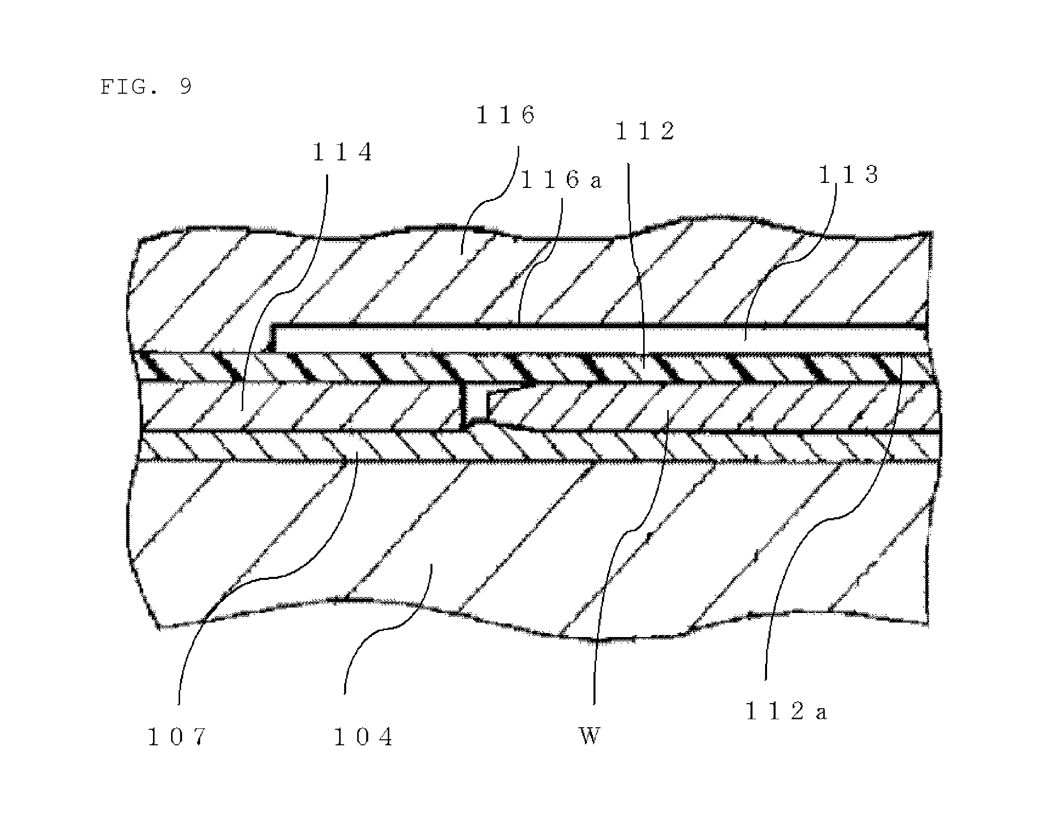
[0010] In view of these problems, Patent Document 1 suggests a polishing head that uniformly presses the entire surface of a workpiece against a polishing surface to uniformly polish this entire surface so that the outer circumferential sag of the workpiece can be prevented and the flatness of the workpiece surface can be improved. This polishing head is shown in FIG. 8 and FIG. 9. FIG. 8 shows a schematic diagram of the whole polishing head. FIG. 9 shows an enlarged view of a part of this conventional polishing head.
[0011] The polishing head 117 includes a head 120 having a hollow that forms a holding part with an opening facing downward, a holder 121 disposed inside the hollow of the head 120, an elastic body 110 having an outer end fixed to a wall of the head 120 and an inner end fixed to the holder 121 that hangs the holder 121 while allowing a minute amount of vertical and horizontal movement of the holder, a first pressure chamber 111 defined by the holder 121 and the elastic body in the interior of the head 120, a thin elastic film 112 having an outer end fixed to the outer side of the holder 121 and an outer surface capable of contacting the workpiece W and pressing the workpiece W against the polishing surface of the turn table, and a second pressure chamber 113 defined by an outer surface 116a of the holding plate 116 and an inner surface 112a of the thin elastic film. A first fluid supplying means 122 supplies fluid to the first pressure chamber 111 with a given pressure. A second fluid supplying means 123 supplies fluid to the second pressure chamber 113 with a given pressure.
[0012] The thin elastic film 112 is fixed to the outer surface of the holding plate 116 such that its outer end 112b is put between a fixing ring 115 and the holding plate 116 and screwed by bolts (not shown). This thin elastic film 112 is provided so as to be capable of contacting the workpiece W on its outer surface side and uniformly pressing the workpiece W against the polishing surface of the turn table like an action of an airbag. The workpiece W is surely attached to the surface of the thin elastic film 112 by the surface tension of liquid such as wafer.
[0013] A template 114 that is an annular disc is mounted on the side of the outer surface (the lower surface) of the thin elastic film 112, and formed so as to be capable of surrounding the workpiece W and thereby preventing the workpiece W from skidding. An inner circumferential portion of the template 114, together with an outer circumferential portion of the workpiece W, is pressed by the thin elastic film 112. The thickness of the template 114 is determined to be the same as the thickness of the workpiece W. This enables the outer circumferential portion of the workpiece W to receive a uniform load and prevent the occurrence of its sag.
CITATION LIST
Patent Literature
[0014] Patent Document 1: Japanese Unexamined Patent publication (Kokai) No. H09-29618
[0015] Patent Document 2: Japanese Unexamined Patent publication (Kokai) No. H11-90820
SUMMARY OF INVENTION
Technical Problem
[0016] A polishing process with the polishing head 117 disclosed in Patent Document 1, however, may degrade the flatness of a workpiece. The present inventors considered the reason and found the following.
[0017] Uniformly pressing the inner circumferential portion of the template 114 reduces a gap between the template 114 and the polishing pad 107, thereby making it difficult to supply a polishing agent to the gap between the template 114 and the polishing pad 107. This makes unstable the amount of the polishing agent supplied to the gap between the polishing pad and the outer circumferential portion of the workpiece, thereby causing variation in concentration of abrasive grains of the polishing agent.
[0018] The inventors further investigated the relation between the concentration of abrasive grains of the polishing agent and variation in stack removal of a polished workpiece. The polishing head shown in FIG. 8 was used as a polishing head. A mirror-polished silicon wafer with a diameter of 300 mm was used as a wafer to be polished. The cross-sectional shape of the thickness of the wafer was measured in advance with WaferSight made of KLA-Tencor. A laminating plate composed of a commercially available glass woven fabric impregnated with epoxy resin was used as a template. A commercially available colloidal silica slurry was used as a polishing agent. Colloidal silica having an average diameter of 35 nm to 70 nm was used as abrasive grains. This colloidal silica was deluded with pure water. Potassium hydroxide was added to the resultant slurry such that pH was 10.5.
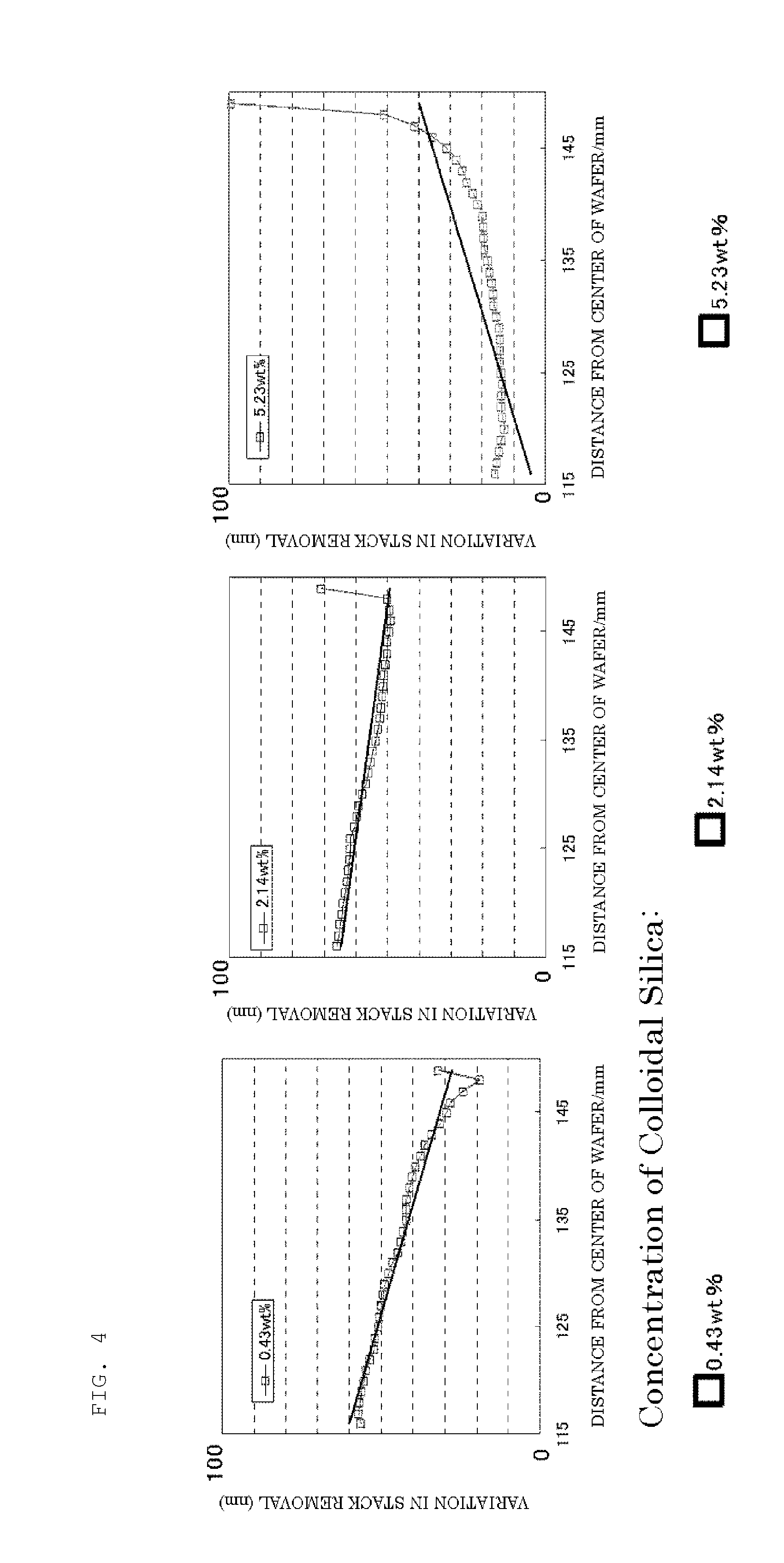
[0019] A commercially available nonwoven fabric was used as a polishing pad. In polishing, the polishing head and the polishing turn table were rotated at 30 rpm. The polishing pressure (the pressure of the fluid) against the wafer was 150 g/cm.sup.2. In polishing processes of three silicon wafers, the dilution ratio of the polishing agent was changed to change the concentration of abrasive grains. After the polished wafers were cleaned, the cross-sectional shape of their thickness was measured with WaferSight made of KLA-Tencor as in before the polishing. The difference in thickness between before and after the polishing was calculated to evaluate the stock removal of the wafers. As shown in FIG. 4, it was revealed that there is a correlative relationship between the concentration of abrasive grains and the stock removal of the wafers; as the concentration of abrasive grains becomes higher, the stock removal of the wafers shifts to a sag side.
[0020] It can accordingly be said that when a polishing agent is supplied to the gap between the polishing pad and the outer circumferential portion of a workpiece during polishing of the workpiece, the occurrence of variation in the abrasive grains concentration of this polishing agent increases the instability of the shape of the outer circumference of the workpiece; the flatness of the workpiece is thus degraded.
[0021] It has been known that a template is provided with a channel penetrating from its outer circumferential end to its inner circumferential end such as a groove, a hole, or a concave passage so that a polishing agent is sufficiently supplied to the gap between the template and the polishing pad (See Patent Document 2). This countermeasure has the problem in that the density of the polishing agent affects the outer circumferential portion of the workpiece because of the groove or hole, creating a winding shape in a circumferential direction; the flatness of the workpiece is thus degraded.
[0022] Providing a groove on a surface of a polishing pad is known as a countermeasure of a polishing pad side. This countermeasure however produces a finely roughened surface of a polished workpiece due to the groove.
[0023] In addition, there is a patent in which a template is used also as a dressing body for the polishing pad surface that has a dressing surface with irregularities for dressing on the polishing pad side of the template. This template however is not practical because when the polishing surface of the polishing pad is roughened during polishing, shavings are created, thereby making scratches on the wafer surface during polishing at a fraction defective more than 10%. In examples of this dressing body, fine irregularities of embossment, fine gentle hollows of dimples, or irregularities radially formed about the center of the dressing surface (including an annular surface) are formed. The size of these irregularities is, for example, about 500 .mu.m.
[0024] The present invention was accomplished in view of the above-described problems. It is an object of the present invention to provide a workpiece polishing apparatus that can stabilize the amount of a polishing agent supplied to a gap between the polishing pad and the outer circumferential portion of a workpiece through a gap between the template and the polishing pad, and inhibit variation in concentration of abrasive grains of the polishing agent. This workpiece polishing apparatus can therefore stabilize a polishing rate of the outer circumferential portion of the workpiece and polish the workpiece into a very flat workpiece.
Solution to Problem
[0025] To achieve this object, the present invention provides a workpiece polishing apparatus comprising: a polishing pad configured to polish a workpiece; a polishing agent supplying mechanism configured to supply a polishing agent; and a polishing head configured to hold the workpiece such that a back surface of the workpiece is held by a backing pad and an edge of the workpiece is held by an annular template; the apparatus being configured to polish the workpiece by pressing the workpiece and the template against the polishing pad and thereby bringing the workpiece into sliding contact with the polishing pad, wherein the template is made of a resin containing filler or woven fabric and has fine depressions on a surface on a side that presses the polishing pad, the fine depressions being created by the filler or woven fabric exposed on the surface on the side that presses the polishing pad.
[0026] In the workpiece polishing apparatus of this type, the polishing agent is easy to pass through a gap between the template and the polishing pad because of the fine depressions lying on a pressing surface of the template; the amount of polishing agent supplied to a gap between the polishing pad and the outer circumferential portion of the workpiece is stabilized; and the polishing agent is supplied to the workpiece surface and the polishing pad surface with a uniform abrasive grains concentration. The shape of the outer circumferential portion of the workpiece can consequently be made flat and a very flat workpiece can be obtained. In addition, since the template is made of the resin containing filler or woven fabric that is exposed on the surface on the side that presses the polishing pad, the fine uniform depressions can be readily formed. These depressions create no shaving of the polishing pad and make no scratch on the wafer.
[0027] The surface coverage of the exposed filler or woven fabric on the surface of the template on the side that presses the polishing pad preferably ranges from 5% to 85%.
[0028] When the surface coverage of the filler or woven fabric is 5% or more, it is more certain that the polishing agent is easy to pass uniformly through the gap between the template and the polishing pad, and variation in concentration of abrasive grains of the polishing agent can be inhibited. Consequently, the flatness of the workpiece can more reliably be made high. When this surface coverage is 85% or less, a workpiece having a low fraction defective (scratch) can reliably be obtained.
[0029] Each of the depressions preferably has a depth of 0.05 mm or more.
[0030] In such an apparatus, it is more certain that the polishing agent is easy to pass through the gap between the template and the polishing pad; the amount of the polishing agent supplied to the gap between the polishing pad and the workpiece is stabilized; and the variation in concentration of abrasive grains of the polishing agent between the polishing pad and the outer circumferential portion of the workpiece can effectively be inhibited. The polishing rate, particularly at the outer circumferential portion of the workpiece is consequently stabilized to polish the workpiece into a very flat workpiece.
[0031] Each of the depressions preferably has an opening with a width of 5 mm or less. The pitches among the depressions are preferably 10 mm or less.
[0032] Such an apparatus can inhibit a winding shape created in a circumferential direction of the workpiece, thereby enabling acquisition of a workpiece having higher flatness.
[0033] The contact angle between each of the depressions and the polishing pad is preferably 90.degree. or less.
[0034] Such an apparatus can polish the workpiece without damaging the polishing pad, thereby enabling acquisition of a workpiece having a low fraction defective (scratch).
Advantageous Effects of Invention
[0035] The inventive polishing apparatus includes the template that is made of a resin containing filler or woven fabric and has fine depressions created by the filler or woven fabric exposed on a surface on a side that presses the polishing pad. This apparatus can thereby make it easy to pass the polishing agent uniformly through the gap between the template and the polishing pad because of the depressions of the template, stabilize the amount of the polishing agent supplied to the gap between the polishing pad and the workpiece, particularly the outer circumferential portion, and supply the polishing agent to the surface of the outer circumferential portion of the workpiece and the surface of the polishing pad with a uniform abrasive grains concentration. The shape of the outer circumferential portion of the workpiece can consequently be made flat and a very flat workpiece can be obtained. In addition, since the template is made of the resin containing filler or woven fabric, and the filler or woven fabric is exposed on the surface on the side that presses the polishing pad, the fine uniform depressions can be readily formed, and a winding shape and a scratch are scarcely created on the polished workpiece.
BRIEF DESCRIPTION OF DRAWINGS
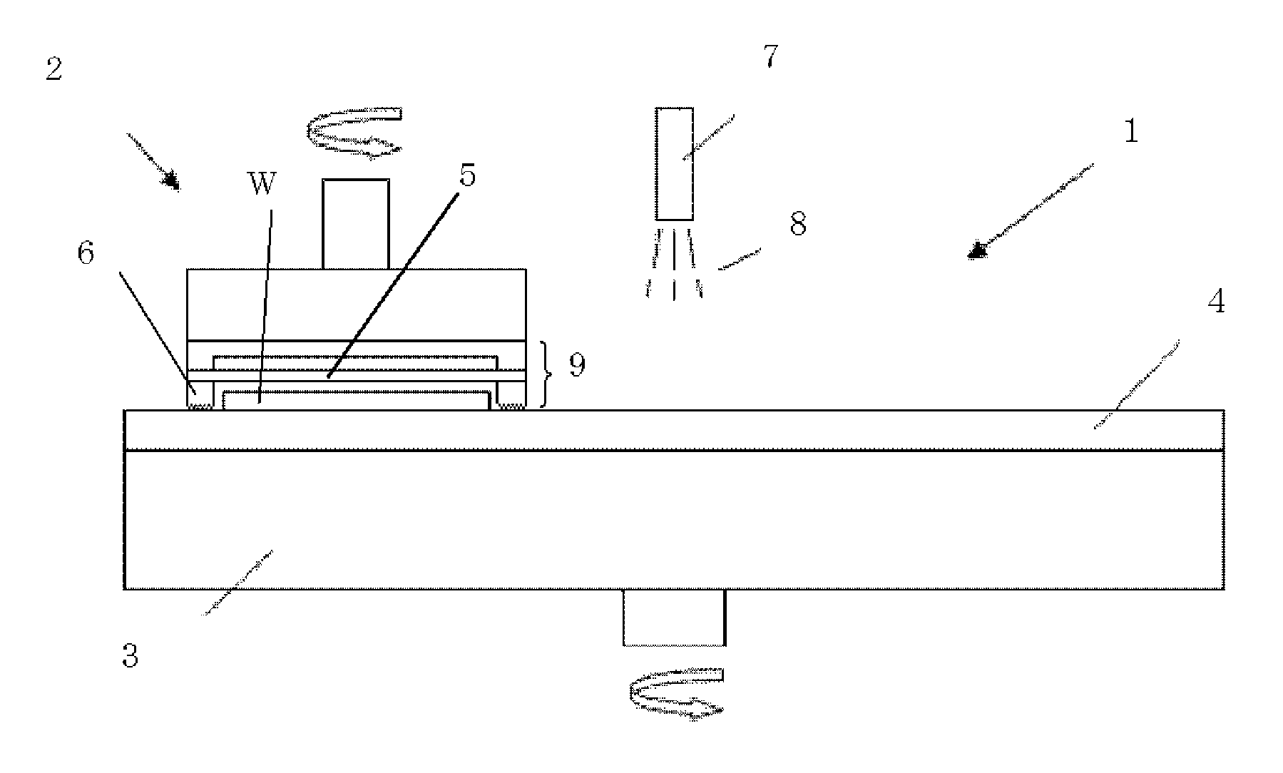
[0036] FIG. 1 is a schematic diagram showing an exemplary polishing apparatus according to the present invention;
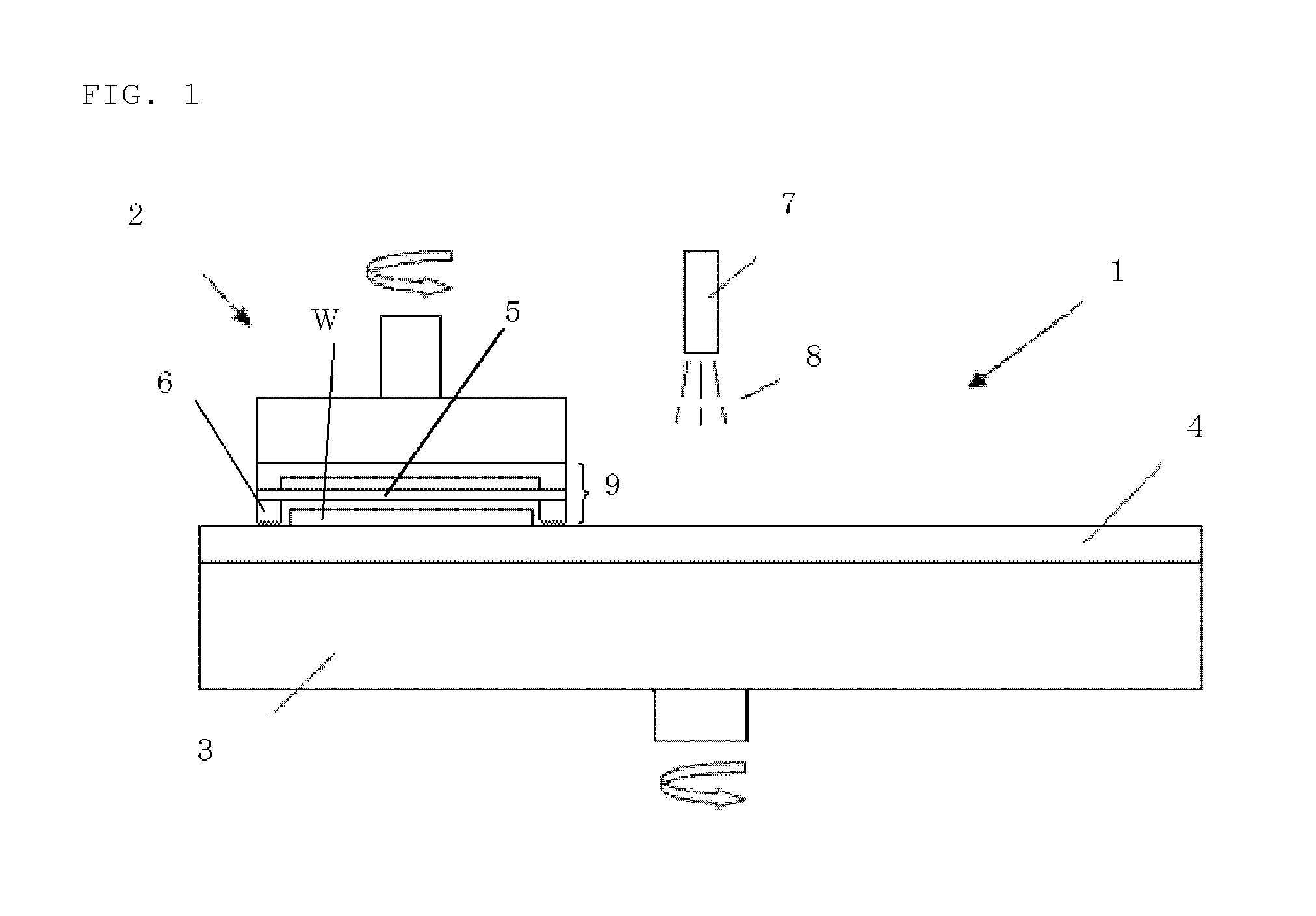
[0037] FIG. 2 is an enlarged view showing an example of the vicinity of a template having an added filler of a polishing head of the inventive polishing apparatus;
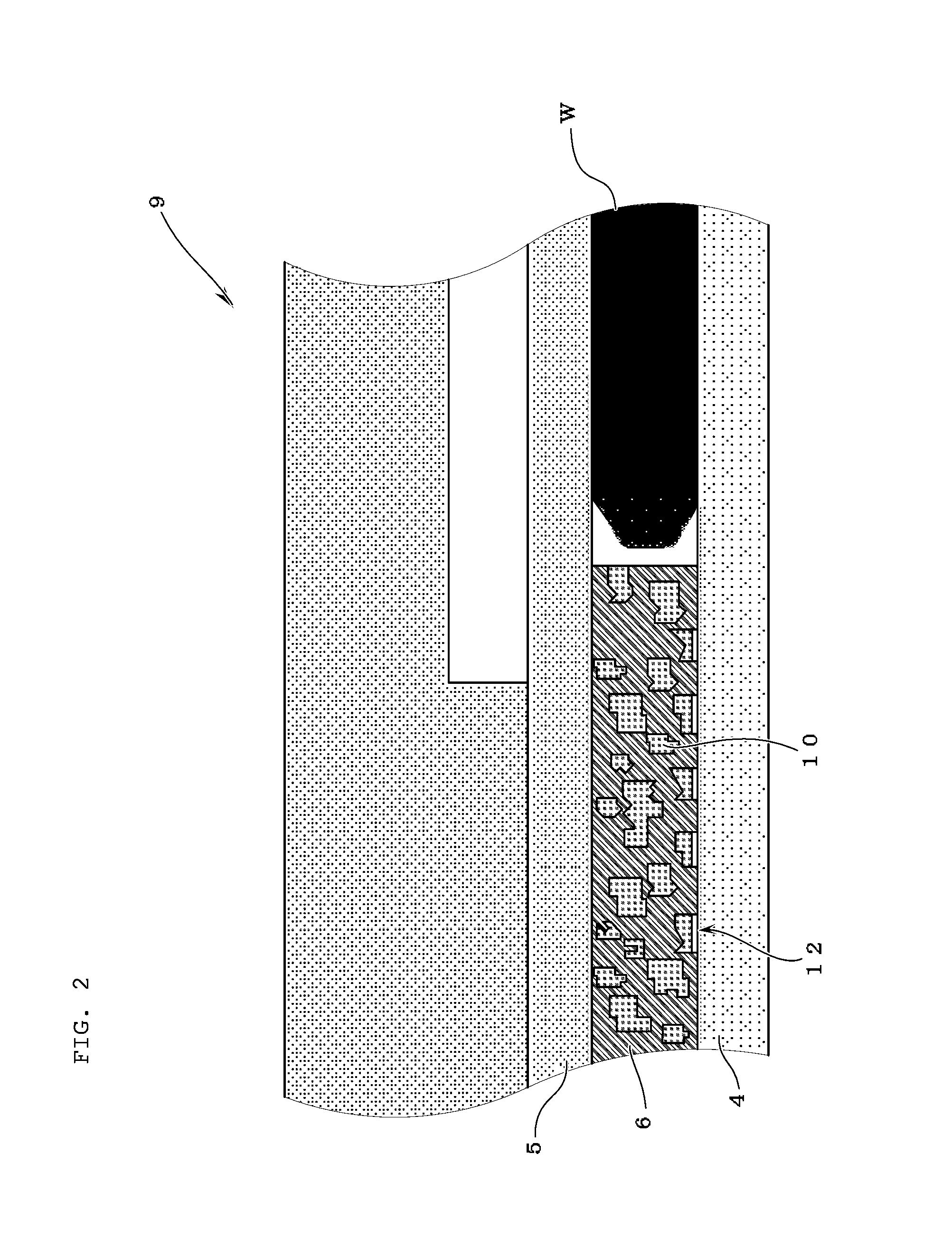
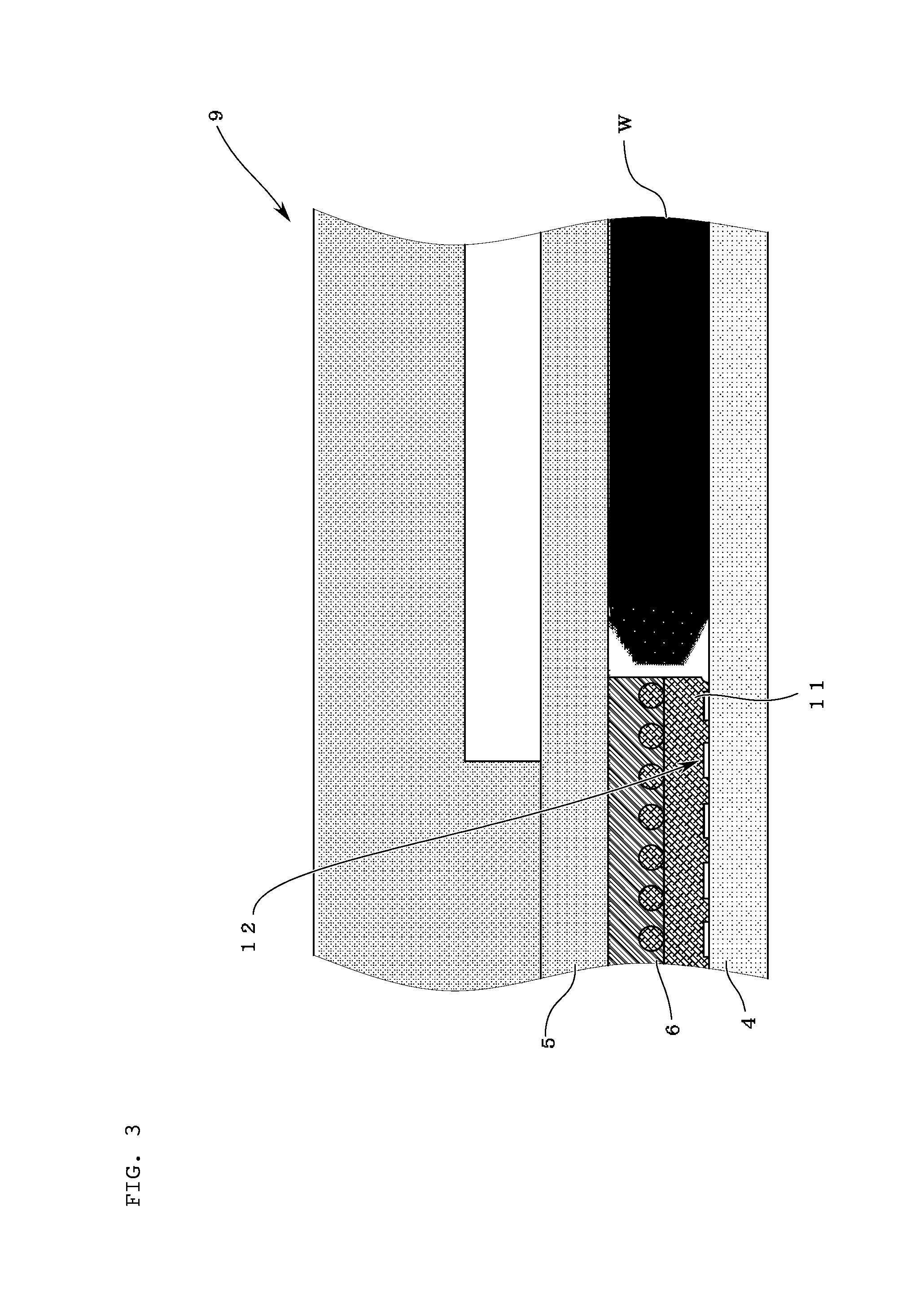
[0038] FIG. 3 is an enlarged view showing an example of the vicinity of a template having an added woven fabric of a polishing head of the inventive polishing apparatus;
[0039] FIG. 4 is a diagram showing the relationship between the concentration of abrasive grains of a polishing agent and variation in stock removal of a polished workpiece;
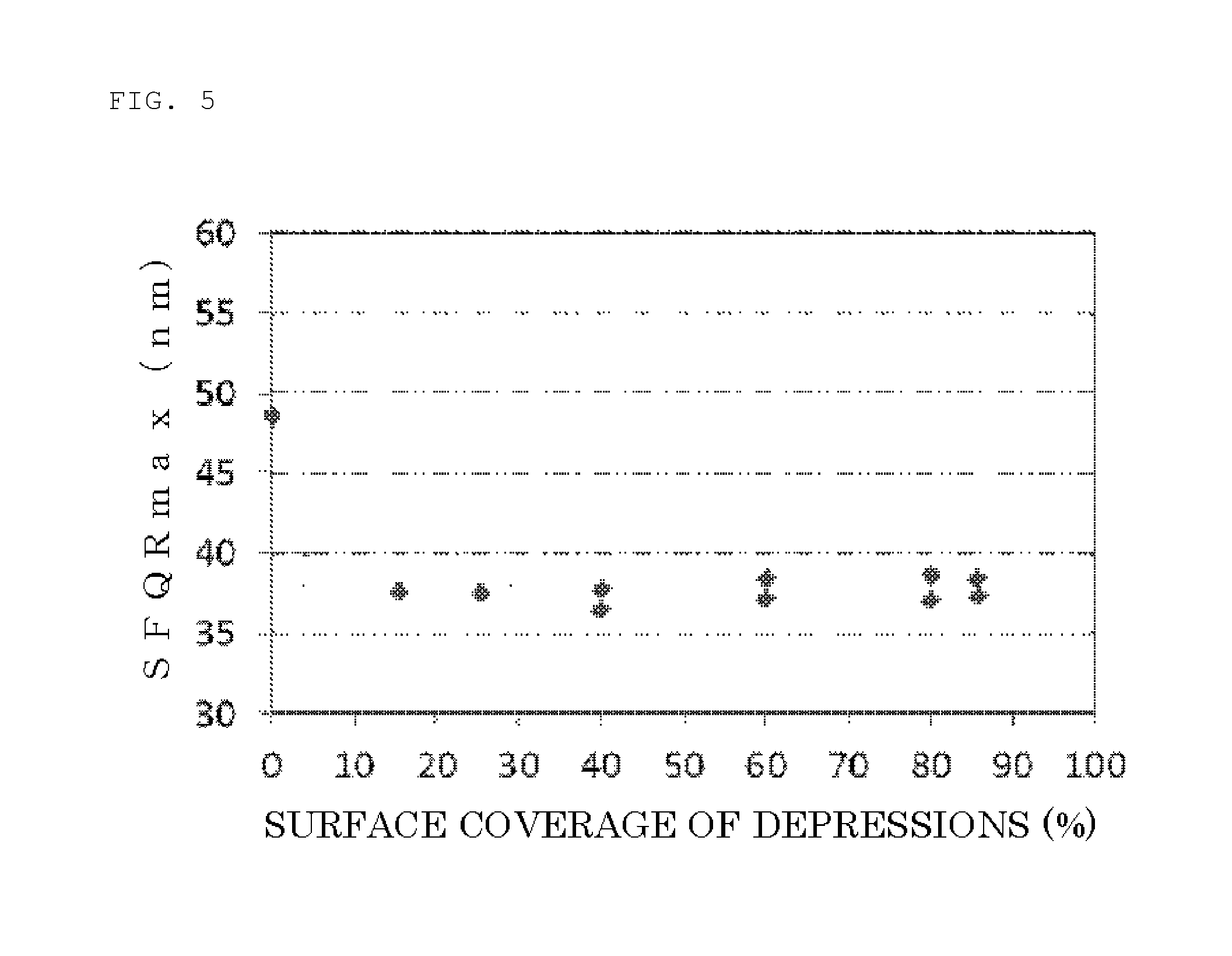
[0040] FIG. 5 is a diagram showing the relationship between the surface flatness of a workpiece and a surface coverage of depressions on the surface of a template on a side that presses a polishing pad in examples 1 and 2 and comparative example;
[0041] FIG. 6 is a diagram showing the relationship between a fraction defective (scratch) of a surface of a workpiece and the surface coverage of depressions on the surface of a template on the side that presses the polishing pad in examples 1 and 2 and comparative example;
[0042] FIG. 7 is a schematic diagram showing an example of a conventional polishing apparatus;
[0043] FIG. 8 is a schematic diagram showing an exemplary polishing head of a conventional polishing apparatus; and
[0044] FIG. 9 is an enlarged view of a part of the polishing head of the conventional polishing apparatus.
DESCRIPTION OF EMBODIMENTS
[0045] An embodiment of the present invention will hereinafter be described, but the present invention is not limited to this embodiment.
[0046] In polishing of a workpiece, uniformly pressing an inner circumferential portion of a template makes it difficult to supply a polishing agent to a gap between the template and a polishing pad and to a gap between the polishing pad and an outer circumferential portion of the workpiece, thereby making it easy to cause variation in concentration of abrasive grains of the polishing agent supplied to the gap between the polishing pad and the workpiece, as described previously. This variation in the abrasive grains concentration increases the instability of the shape of the workpiece, particularly the outer circumference, resulting in the degradation of the flatness of the workpiece.
[0047] In view of this problem, the inventors diligently considered how a very flat workpiece can be obtained in a workpiece polishing process. The inventors consequently thought of a polishing apparatus including a template that is made of a resin containing filler or woven fabric and has fine depressions created by the filler or woven fabric exposed on the surface on the side that presses the polishing pad. The apparatus of this type can readily pass the polishing agent uniformly through the gap between the template and the polishing pad over the depressions, stabilize the amount of the polishing agent supplied to the gap between the polishing pad and the outer circumferential portion of the workpiece and supply the polishing agent to the surface of the workpiece and the surface of the polishing pad with a uniform abrasive grains concentration. The shape of the workpiece, particularly the outer circumferential portion, can consequently be made flat and a very flat workpiece can be obtained. The inventors made these findings, thereby brought the invention to completion.
[0048] The inventive workpiece polishing apparatus will now be described in detail with reference to the drawings, but the invention is not limited thereto.
[0049] As shown in FIG. 1, the inventive polishing apparatus 1 is constituted of a polishing pad 4 used to polish a workpiece, a polishing agent supplying mechanism 7 used to supply a polishing agent 8, and a polishing head 2 used to hold the workpiece W. The polishing pad 4 is attached to a turn table 3. The polishing head 2 has a baking pad 5 to hold the back surface of the workpiece W and an annular template 6 to hold the edge of the workpiece W.
[0050] This polishing apparatus 1 holds the back surface of the workpiece W by the backing pad 5 and the edge of the workpiece W by the template 6, and presses the workpiece W and the template 6 against the polishing pad 4 thereby to bring the workpiece W into sliding contact with the polishing pad 4 while supplying the polishing agent 8 to the polishing pad 4 through the polishing agent supplying mechanism 7 and rotating the turn table 3 and the polishing head 2, so that the workpiece W is polished.
[0051] FIG. 2 and FIG. 3 each show schematically an example of an enlarged periphery 9 of the polishing head. As shown in FIG. 2, the template 6 is made of a resin containing filler 10. Because the surface configured to press the polishing pad 4 exposes the filler 10, the template 6 has fine depressions 12 on this pressing surface. Alternatively, as shown in FIG. 3, the template 6 is made of a resin containing woven fabric 11. Because the surface configured to press the polishing pad 4 exposes the woven fabric 11, the template 6 has fine depressions 12 on this pressing surface.
[0052] Other components of the polishing head 2 are not particularly limited; any configuration may be acceptable, provided the backing pad and the template having the depressions can hold the back surface and edge of the workpiece respectively.
[0053] The polishing apparatus 1 can readily pass the polishing agent 8 uniformly through the gap between the template 6 and the polishing pad 4 because of the interposition of the depressions 12 of the template 6, stabilize the amount of polishing agent 8 supplied to the gap between the polishing pad 4 and the outer circumferential portion of the workpiece W and supply the polishing agent 8 to the surface of the workpiece W and the surface of the polishing pad 4 with a uniform abrasive grains concentration. The polishing rate of the workpiece W, particularly at the outer circumferential portion, is consequently stabilized within the circumference, so the shape of this outer circumferential portion can be made flat. A very flat workpiece W can thus be obtained. Since the template 6 having a proper thickness is made of the resin containing filler 10 or woven fabric 11, and the filler 10 or woven fabric 11 is exposed on the surface configured to press the polishing pad 4, the fine depressions 12 can therefore be readily formed uniformly. The formation of the fine depressions 12 needs no complicated processing apparatus nor processing method, so the cost can be reduced to a lower level.
[0054] The surface coverage of the exposed filler 10 or woven fabric 11 on the surface of the template 6 on the side that presses the polishing pad 4 preferably ranges from 5% to 85%, more preferably to 80%.
[0055] When the surface coverage of the filler 10 or woven fabric 11 is 5% or more, the amount of polishing agent 8 supplied to the gap between the polishing pad 4 and the outer circumferential portion of the workpiece W can be stabilized, and the polishing agent 8 supplied to the gap between the polishing pad 4 and the outer circumferential portion of the workpiece W can be inhibited from varying its abrasive grains concentration, so the flatness of the workpiece W can more reliably be improved. When this surface coverage is 85% or less, the surface of the template 6 on the side that presses the polishing pad 4 can be inhibited from wearing down, and the occurrence of shavings can be inhibited. Consequently, a workpiece W having a low fraction defective can reliably be obtained.
[0056] The depth of the depressions 12 is preferably 0.05 mm or more.
[0057] In this manner, the depressions 12 can be maintained for a long period of time even when the surface of the template 6 is also polished during polishing of the workpiece, so the lifetime of the template can be improved.
[0058] Moreover, the depth of the opening of each depression 12 is preferably 5 mm or less. The pitch among each depression 12 is preferably 10 mm or less.
[0059] In this manner, the outer circumferential portion of the workpiece can be inhibited from being affected by the density of the polishing agent 8, so the occurrence of a winding shape in a circumferential direction of the workpiece W can be inhibited. A flatter workpiece W can consequently be obtained.
[0060] The contact angle between each depression 12 and the polishing pad 4 is preferably 90.degree. or less.
[0061] In this manner, the workpiece W can be polished without damaging the polishing pad 4 by the depressions 12. A workpiece W with a lower fraction defective can consequently be obtained.
EXAMPLE
[0062] The present invention will be more specifically described below with reference to examples and a comparative example, but the invention is not limited to these examples.
Example 1
[0063] A workpiece was polished with the inventive workpiece polishing apparatus to evaluate the flatness of the polished workpiece and the scratch fraction defective.
[0064] The polishing apparatus shown in FIG. 1 was used in example 1. The polishing head shown in FIG. 2 was used in this polishing apparatus. This polishing head was the same as the polishing head shown in FIG. 8 except for the template. The template used herein was produced in the following manner. A bisphenol A based epoxy resin containing a glass filler having a maximum dimension of 2 mm and an adjusted concentration was prepared. This resin was applied by spraying to produce an epoxy resin prepreg containing glass fiber. This prepreg was stacked such that the prepreg was disposed on the side configured to press the polishing pad. The resultant was formed into an annular shape under pressure. The thickness of the template was 750 .mu.m. The surface coverage of the exposed filler on the surface on the side configured to press the polishing pad was 25%.
[0065] A 300-mm-diameter silicon wafer was used as a subject to be polished. A commercially available slurry of colloidal silica that was deluded with pure water and contained potassium hydroxide so as to have a pH of 10.5 was used as the polishing agent. The average diameter of abrasive grains of this colloidal silica was in the range from 35 nm to 70 nm. The polishing pad used was a commercially available nonwoven fabric. In the polishing, the polishing head and the polishing turn table were rotated at 30 rpm. The polishing pressure (the pressure of fluid) against the wafer was 150 g/cm.sup.2. After the wafer was polished, the wafer was cleaned. The flatness of the wafer was then measured with WaferSight made by KLA-Tencor to evaluate SFQRmax. The fraction defective on the surface was also evaluated with SP-1 made by KLA-Tencor.
Example 2
[0066] A workpiece was polished under the same conditions as example 1 except that the template differed in the following points. The flatness and the fraction defective of the polished workpiece were evaluated. In this example, the template was produced in the following manner. A flat fabric type of glass fiber cloth with a thickness of 0.18 mm and a horizontal and vertical pitch of 0.5 mm was impregnated with a bisphenol A based epoxy resin. The resultant was dried to produce a prepreg for a front surface. This prepreg was stacked such that the prepreg was disposed configured to press the polishing pad. The resultant was formed into an annular shape with a thickness of 760 .mu.m under pressure. The surface configured to press the polishing pad was then polished to expose the glass fiber in a netlike form. The template had a 16% surface coverage of the exposed glass fiber cloth on the surface configured to press the polishing pad.
Comparative Example
[0067] A workpiece was polished under the same conditions as example 1 except that a conventional template having no depression unlike the present invention was used. The flatness and the fraction defective of the polished workpiece were evaluated. In this comparative example, the template was produced by using a commercially available epoxy resin disc containing glass fiber. The thickness of the template was 750 .mu.m. The template had no depression created by an exposed filler or glass fiber cloth on the surface configured to press the polishing pad. In other words, the surface coverage of depressions was 0%.
[0068] In examples 1 and 2, polishing was repeated in the same manner except that the surface coverage of the depressions was changed to 40%, 60%, 80%, and 85%. The result is shown in FIG. 5 and FIG. 6. FIG. 5 shows the correlation between the surface coverage of the depressions on the surface of the template on the side configured to press the polishing pad and SFQRmax. Comparing the flatness in examples 1 and 2 with that in comparative example, examples 1 and 2 demonstrated that the shape of the outer circumference of the wafer was flat or a weak sag and SFQRmax was good; comparative example demonstrated that many wafers had a strong rise shape at their outer circumferential portion and SFQRmax was degraded.
[0069] FIG. 6 shows the correlation between the surface coverage of the depressions on the surface of the template on the side configured to press the polishing pad and the fraction defective. The measurement of the fraction defective in examples 1 and 2 and comparative example revealed that when the surface coverage of the depressions was 40%, 60%, or 80%, a wafer that was substantially free of scratches was obtained. When the surface coverage of the depressions was 85%, the fraction defective was somewhat increased, but still a lower level than a fraction defective more than 10% that was exhibited by the conventional apparatus.
[0070] It is to be noted that the present invention is not limited to the foregoing embodiment. The embodiment is just an exemplification, and any examples that have substantially the same feature and demonstrate the same functions and effects as those in the technical concept described in claims of the present invention are included in the technical scope of the present invention.
* * * * *
D00000
D00001
D00002
D00003
D00004
D00005
D00006
D00007
D00008
D00009
XML
uspto.report is an independent third-party trademark research tool that is not affiliated, endorsed, or sponsored by the United States Patent and Trademark Office (USPTO) or any other governmental organization. The information provided by uspto.report is based on publicly available data at the time of writing and is intended for informational purposes only.
While we strive to provide accurate and up-to-date information, we do not guarantee the accuracy, completeness, reliability, or suitability of the information displayed on this site. The use of this site is at your own risk. Any reliance you place on such information is therefore strictly at your own risk.
All official trademark data, including owner information, should be verified by visiting the official USPTO website at www.uspto.gov. This site is not intended to replace professional legal advice and should not be used as a substitute for consulting with a legal professional who is knowledgeable about trademark law.