Electronic atomizing device
Lai , et al. April 26, 2
U.S. patent number D950,144 [Application Number D/736,757] was granted by the patent office on 2022-04-26 for electronic atomizing device. This patent grant is currently assigned to SHENZHEN SMOORE TECHNOLOGY LIMITED. The grantee listed for this patent is Shenzhen Smoore Technology Limited. Invention is credited to Chaoyong Bie, Baosheng Lai.


View All Diagrams
| United States Patent | D950,144 |
| Lai , et al. | April 26, 2022 |
Electronic atomizing device
Claims
CLAIM The ornamental design for an electronic atomizing device, as shown and described.
| Inventors: | Lai; Baosheng (Shenzhen, CN), Bie; Chaoyong (Shenzhen, CN) | ||||||||||
|---|---|---|---|---|---|---|---|---|---|---|---|
| Applicant: |
|
||||||||||
| Assignee: | SHENZHEN SMOORE TECHNOLOGY
LIMITED (Shenzhen, CN) |
||||||||||
| Appl. No.: | D/736,757 | ||||||||||
| Filed: | June 2, 2020 |
Foreign Application Priority Data
| Dec 6, 2019 [CN] | 201930682449.4 | |||
| Current U.S. Class: | D27/162 |
| Current International Class: | 2702 |
| Field of Search: | ;D27/100,101,162,163,164,165,166,167,168,169,170,171,172,173,174,175,176,177,178,179,180,181,182,183,184,185,186,187,188,189,190,191,192,193,194,196 ;D28/91.1 ;D23/360,362 ;D24/110,110.4,110.5,110.6,113 |
References Cited [Referenced By]
U.S. Patent Documents
| D776051 | January 2017 | Wang |
| D788362 | May 2017 | Qiu |
| D807576 | January 2018 | Liu |
| D814693 | April 2018 | Qiu |
| D821305 | June 2018 | Liu |
| D852409 | June 2019 | Takehara |
| D863672 | October 2019 | Liu |
| D864475 | October 2019 | Pierce |
| D872933 | January 2020 | Santos |
| D890416 | July 2020 | Ouyang |
| D897596 | September 2020 | Huang |
| D908281 | January 2021 | Folkerts |
| D910234 | February 2021 | Sun |
| D931202 | September 2021 | Lai |
| 2017/0064999 | March 2017 | Perez |
| 2021/0059304 | March 2021 | Ouyang |
| 202030005770.1 | Jun 2020 | CN | |||
| 202030056801.6 | Jun 2020 | CN | |||
| 201930693892.1 | Sep 2020 | CN | |||
| 202030266056.8 | Oct 2020 | CN | |||
| 202030266330.1 | Dec 2020 | CN | |||
Other References
|
70 Watts of AiO Power. By RiP Trippers. Dated Jan. 27, 2020. Found online [Apr. 26, 2021]. https://www.youtube.com/watch?v=Gep65R5pfao (Year: 2020). cited by examiner . Target PM80 Pod Mod. By Mike Vapes. Dated Dec. 29, 2019. Found online [Apr. 26, 2021]. https://www.youtube.com/watch?v=qDQwCT2GQsY (Year: 2019). cited by examiner . Smok Scar P5 and P3 Pod Mod. By BestVapeGears. Dated Jun. 18, 2020. Found online [Apr. 26, 2021]. https://www.youtube.com/watch?v=Aj1Lj_iws5g (Year: 2020). cited by examiner. |
Primary Examiner: Cash; Marissa J
Assistant Examiner: Melliar; William B
Description
FIG. 1 is a perspective view of an electronic atomizing device shown in an assembled configuration of use according to a first embodiment;
FIG. 2 is another perspective view thereof;
FIG. 3 is a front elevational view thereof;
FIG. 4 is a rear elevational view thereof;
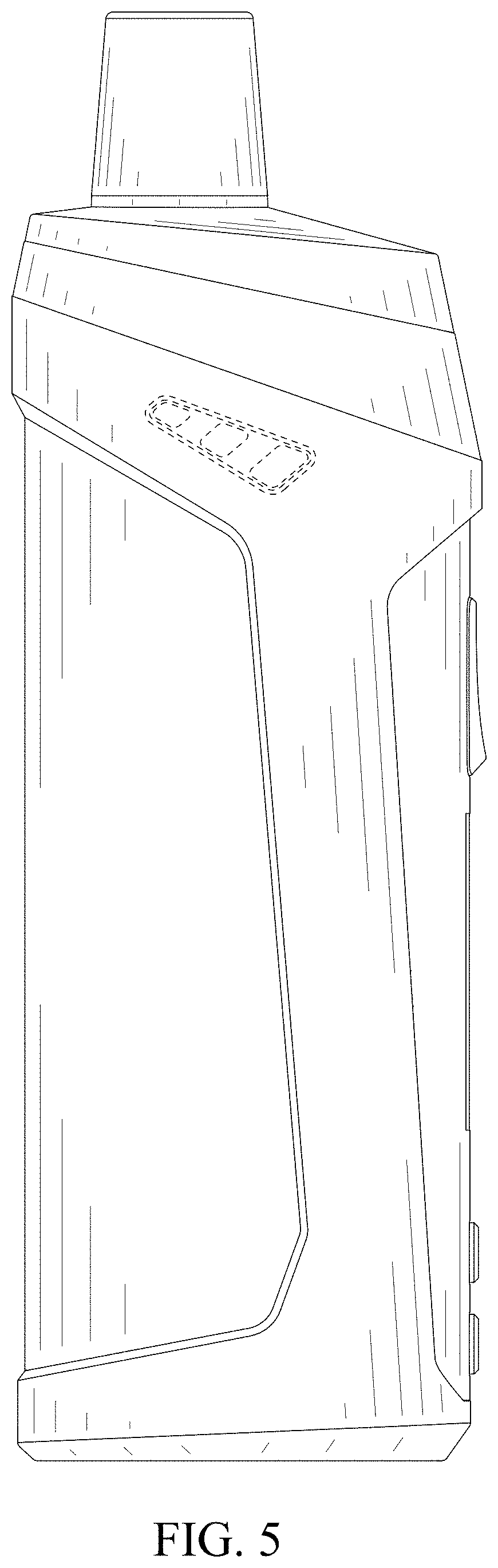
FIG. 5 is a left side elevational view thereof;
FIG. 6 is a right side elevational view thereof;
FIG. 7 is an enlarged top plan view thereof;
FIG. 8 is an enlarged bottom plan view thereof;
FIG. 9 is an enlarged perspective view of an electronic atomizing device showing a first component removed from the assembly in FIGS. 1-8 for clarity of disclosure;
FIG. 10 is another enlarged perspective view thereof;
FIG. 11 is an enlarged front elevational view thereof;
FIG. 12 is an enlarged rear elevational view thereof;
FIG. 13 is an enlarged left side elevational view thereof;
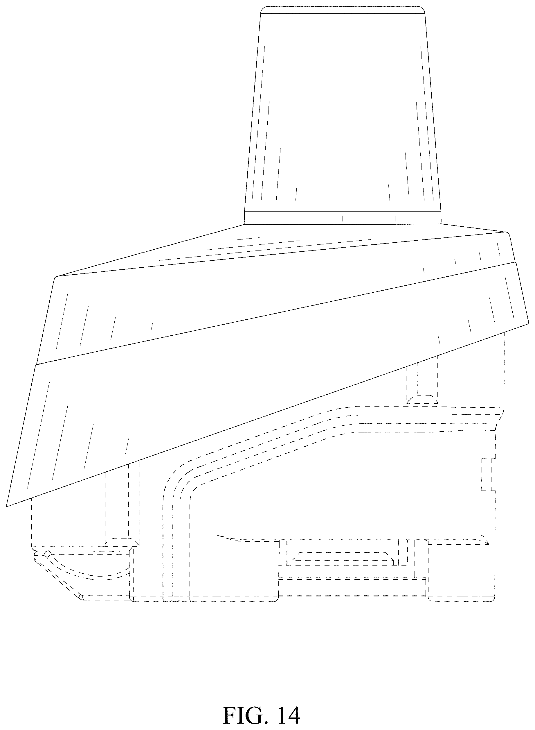
FIG. 14 is an enlarged right side elevational view thereof;
FIG. 15 is an enlarged top plan view thereof;
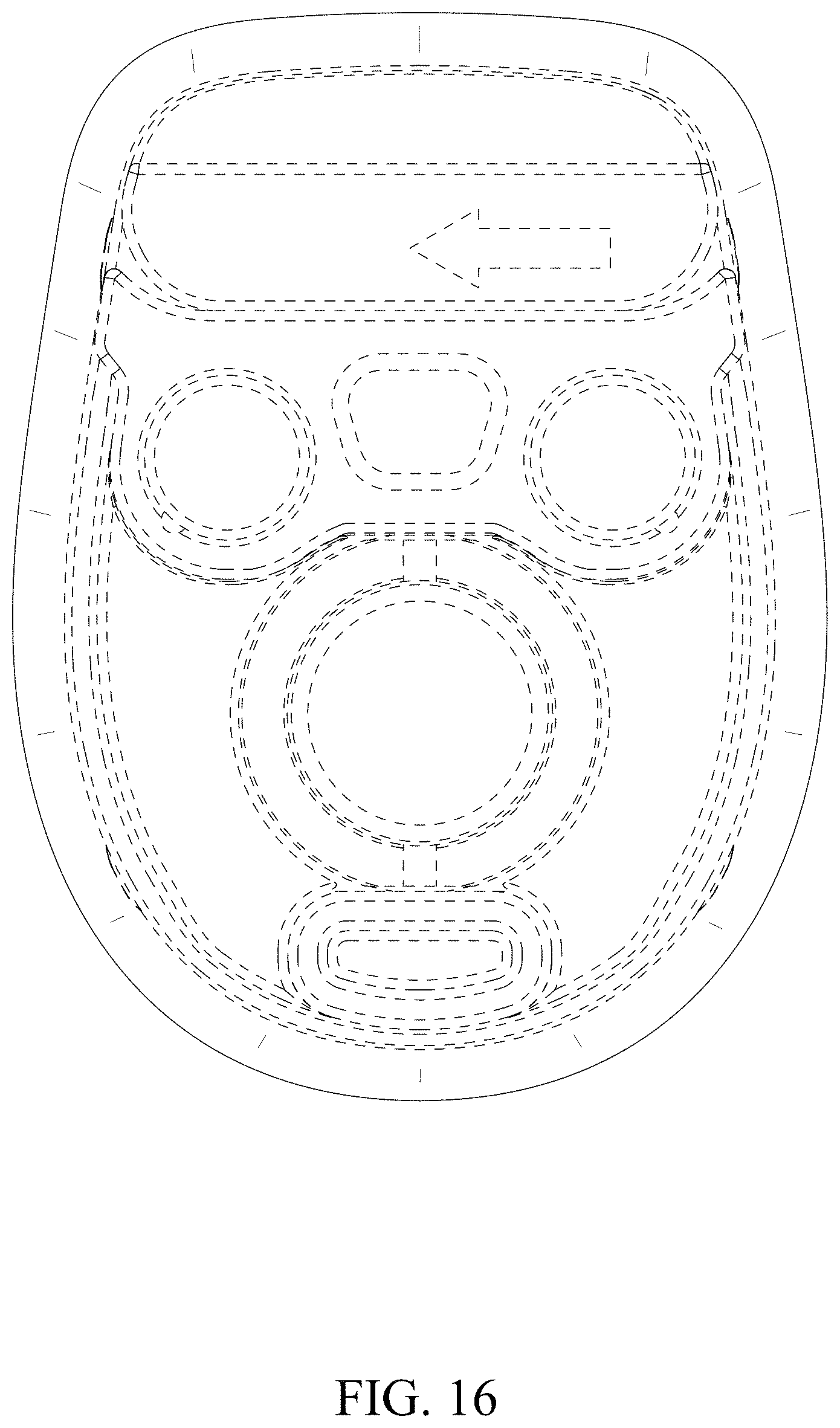
FIG. 16 is an enlarged bottom plan view thereof;
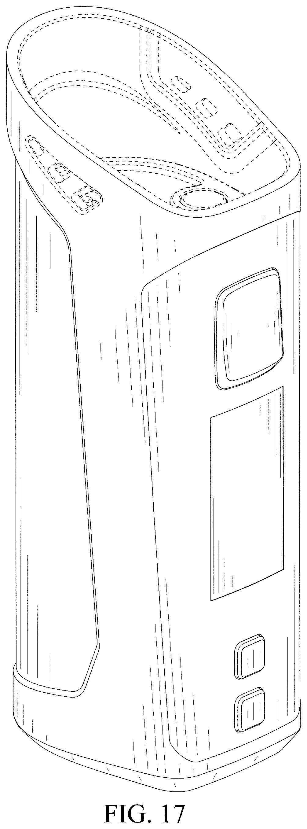
FIG. 17 is an enlarged perspective view of an electronic atomizing device showing a second component removed from the assembly in FIGS. 1-8 for clarity of disclosure;
FIG. 18 is another enlarged perspective view thereof;
FIG. 19 is an enlarged front elevational view thereof;
FIG. 20 is an enlarged rear elevational view thereof;
FIG. 21 is an enlarged left side elevational view thereof;
FIG. 22 is an enlarged right side elevational view thereof;
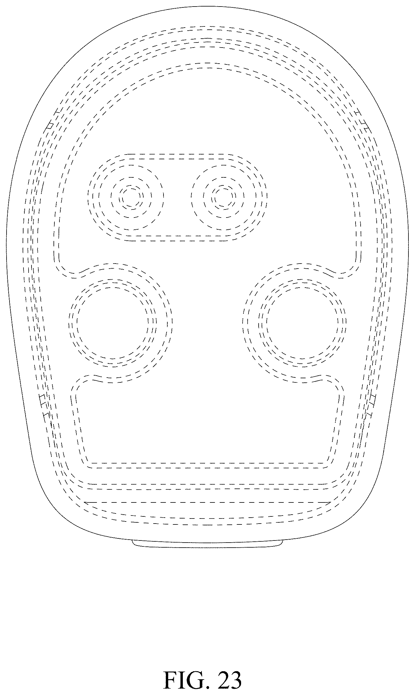
FIG. 23 is an enlarged top plan view thereof;
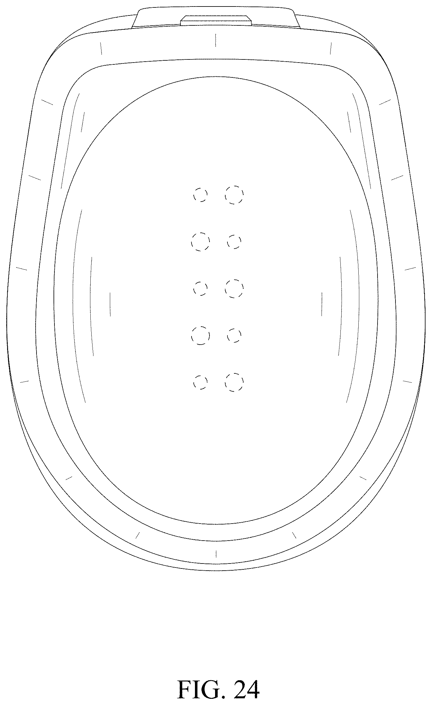
FIG. 24 is an enlarged bottom plan view thereof;
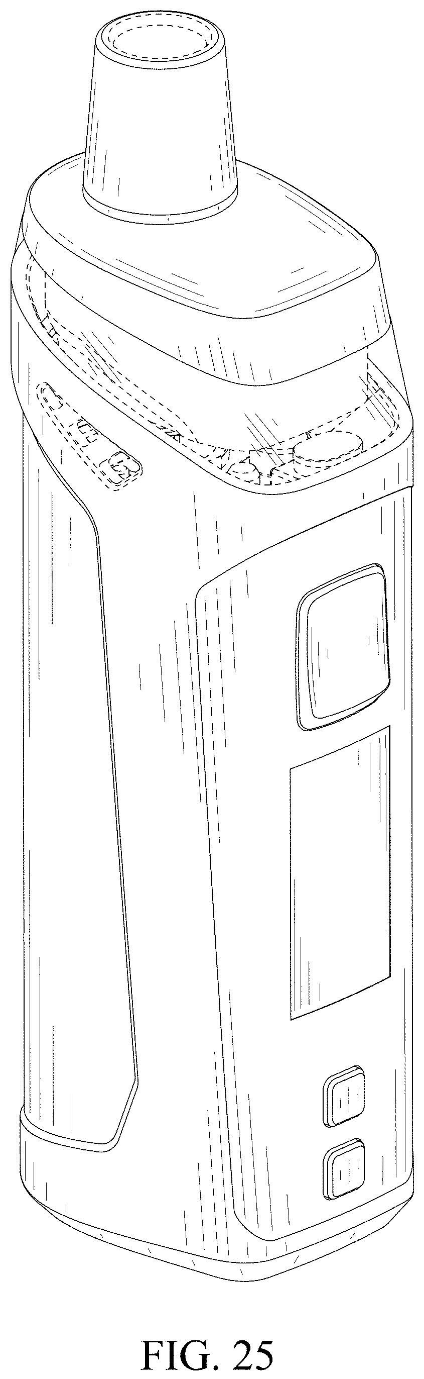
FIG. 25 is a perspective view of an electronic atomizing device shown in an assembled configuration of use according to a second embodiment;
FIG. 26 is another perspective view thereof;
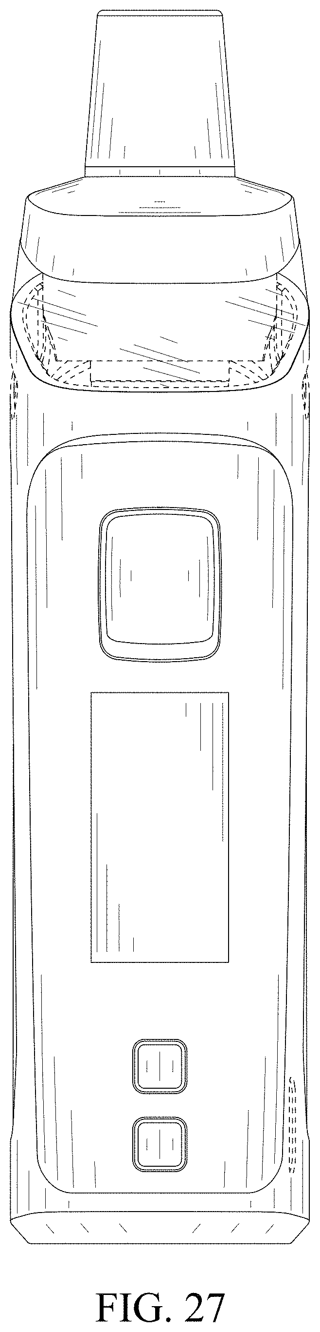
FIG. 27 is a front elevational view thereof;
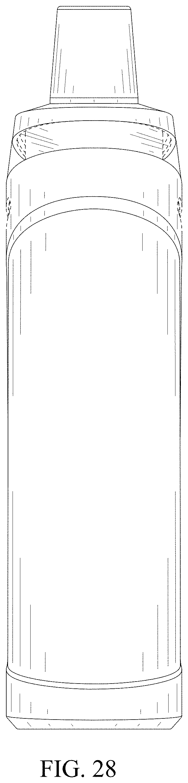
FIG. 28 is a rear elevational view thereof;
FIG. 29 is a left side elevational view thereof;
FIG. 30 is a right side elevational view thereof;
FIG. 31 is an enlarged top plan view thereof;
FIG. 32 is an enlarged bottom plan view thereof;
FIG. 33 is an enlarged perspective view of an electronic atomizing device showing a first component removed from the assembly in FIGS. 25-32 for clarity of disclosure;
FIG. 34 is another enlarged perspective view thereof;
FIG. 35 is an enlarged front elevational view thereof;
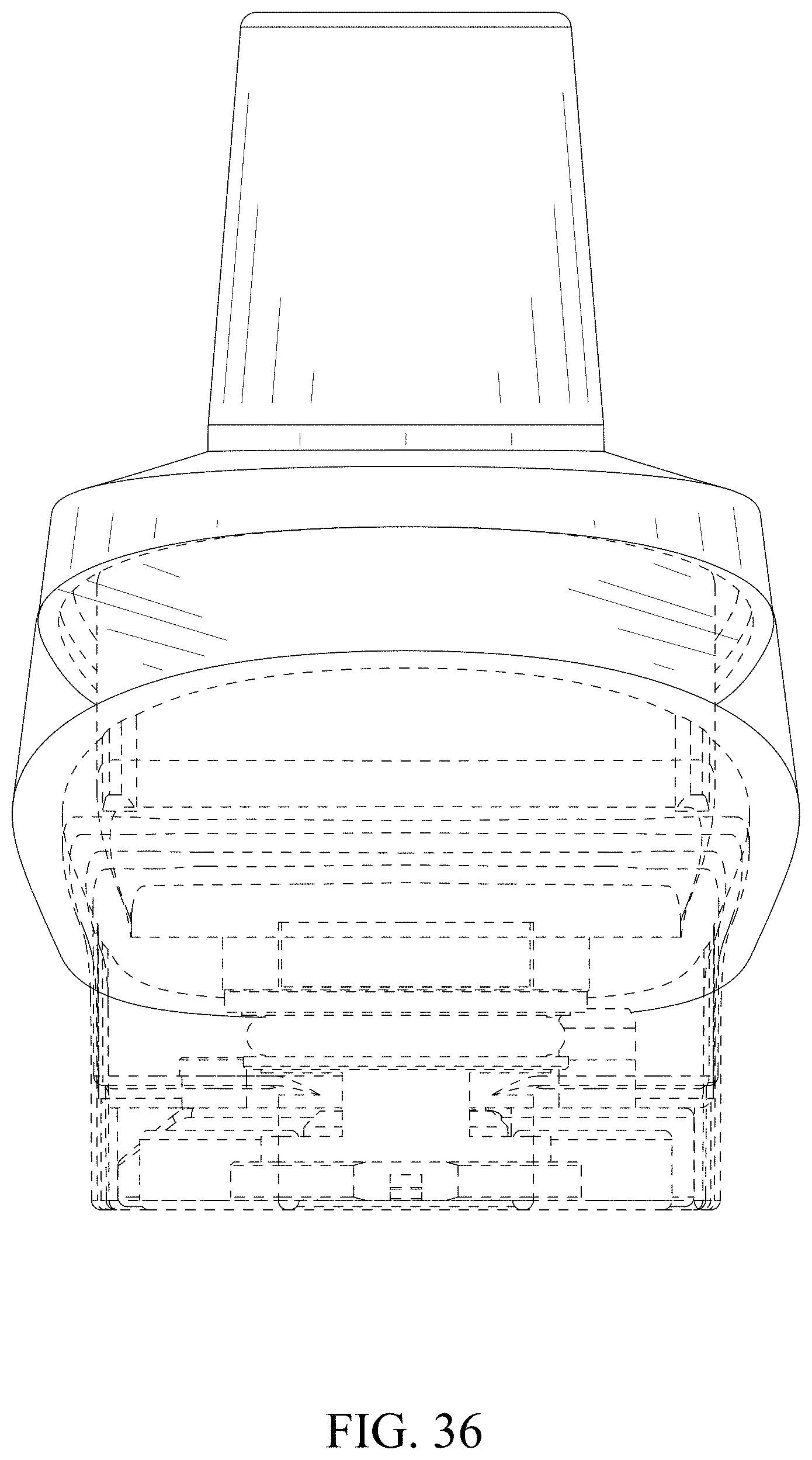
FIG. 36 is an enlarged rear elevational view thereof;
FIG. 37 is an enlarged left side elevational view thereof;
FIG. 38 is an enlarged right side elevational view thereof;
FIG. 39 is an enlarged top plan view thereof; and,
FIG. 40 is an enlarged bottom plan view thereof.
The broken lines in the drawings depict portions of the electronic atomizing device that form no part of the claimed design.
The oblique shade lines in the drawings indicate transparency.
* * * * *
References
D00000
D00001
D00002
D00003
D00004
D00005
D00006
D00007
D00008
D00009
D00010
D00011
D00012

D00013

D00014
D00015

D00016
D00017
D00018

D00019

D00020

D00021

D00022

D00023
D00024
D00025
D00026

D00027
D00028
D00029

D00030

D00031

D00032

D00033

D00034

D00035

D00036
D00037

D00038

D00039

D00040

XML
uspto.report is an independent third-party trademark research tool that is not affiliated, endorsed, or sponsored by the United States Patent and Trademark Office (USPTO) or any other governmental organization. The information provided by uspto.report is based on publicly available data at the time of writing and is intended for informational purposes only.
While we strive to provide accurate and up-to-date information, we do not guarantee the accuracy, completeness, reliability, or suitability of the information displayed on this site. The use of this site is at your own risk. Any reliance you place on such information is therefore strictly at your own risk.
All official trademark data, including owner information, should be verified by visiting the official USPTO website at www.uspto.gov. This site is not intended to replace professional legal advice and should not be used as a substitute for consulting with a legal professional who is knowledgeable about trademark law.