Beverage carton
Dammers , et al. May 18, 2
U.S. patent number D919,431 [Application Number D/639,937] was granted by the patent office on 2021-05-18 for beverage carton. This patent grant is currently assigned to SIG Technology AG. The grantee listed for this patent is SIG Technology AG. Invention is credited to Matthias Dammers, Magdalena Gartner, Thomas Keck.


View All Diagrams
| United States Patent | D919,431 |
| Dammers , et al. | May 18, 2021 |
Beverage carton
Claims
CLAIM The ornamental design for beverage carton, as shown and described.
| Inventors: | Dammers; Matthias (Alsdorf, DE), Gartner; Magdalena (Aachen, DE), Keck; Thomas (Aachen, DE) | ||||||||||
|---|---|---|---|---|---|---|---|---|---|---|---|
| Applicant: |
|
||||||||||
| Assignee: | SIG Technology AG (Neuhausen am
Rheinfall, CH) |
||||||||||
| Appl. No.: | D/639,937 | ||||||||||
| Filed: | March 9, 2018 |
Related U.S. Patent Documents
| Application Number | Filing Date | Patent Number | Issue Date | ||
|---|---|---|---|---|---|
| 35502316 | Sep 6, 2016 | D844430 | |||
Foreign Application Priority Data
| Apr 4, 2016 [EM] | 003055391 | |||
| Current U.S. Class: | D9/431 |
| Current International Class: | 0901 |
| Field of Search: | ;D9/414,424,430-432,500,503,504,522,529,668,702,711,715 |
References Cited [Referenced By]
U.S. Patent Documents
| D333781 | March 1993 | Kobel |
| 5716471 | February 1998 | Pape |
| D518371 | April 2006 | Franic |
| D609088 | February 2010 | Kvam |
| D623537 | September 2010 | Berman |
| D634625 | March 2011 | Wallace et al. |
| 7934637 | May 2011 | Kaneko |
| 8152376 | April 2012 | Rosentreter |
| D668539 | October 2012 | Barbieri et al. |
| D677565 | March 2013 | Barbieri et al. |
| D691882 | October 2013 | Barbieri et al. |
| D702117 | April 2014 | Dagnino |
| D714638 | October 2014 | Mohn et al. |
| D717644 | November 2014 | Franic |
| D721576 | January 2015 | De Pietri Tonelli et al. |
| D721591 | January 2015 | Hefetz et al. |
| D748470 | February 2016 | Mohn et al. |
| D795686 | August 2017 | Mohn et al. |
| D803044 | November 2017 | Franic |
| D832099 | October 2018 | Cavazza |
| D835987 | December 2018 | Moroni |
| D835997 | December 2018 | Vandenbos |
| D835998 | December 2018 | Vandenbos |
| D837050 | January 2019 | Moroni |
| D844430 | April 2019 | Dammers |
| D845123 | April 2019 | Paradiso |
| D852620 | July 2019 | D'Alfonso |
| D902709 | November 2020 | De Pietri Tonelli |
| 2007/0170233 | July 2007 | Fontanazzi |
| 2011/0303739 | December 2011 | Franic |
Other References
|
"More Packaging News for Wine"; Packaging Digest; May 2004; p. 2; vol. 41, No. 5. cited by applicant . I.D. The International Design Magazine; May 2007; p. 79; vol. 54, No. 3; Magazine Publications, LP.; New York, New York. cited by applicant. |
Primary Examiner: Hill; Keli L
Attorney, Agent or Firm: The Webb Law Firm
Description
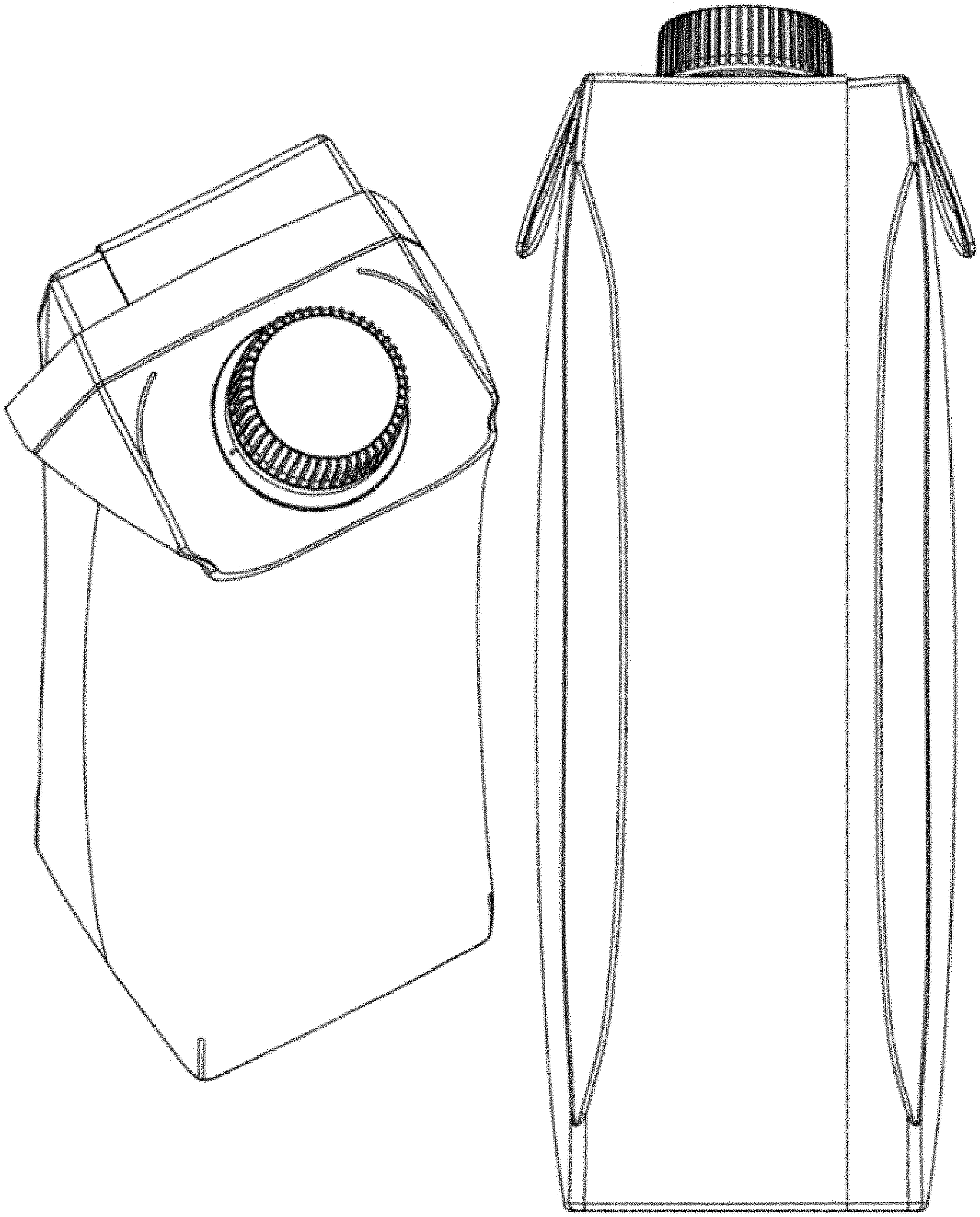
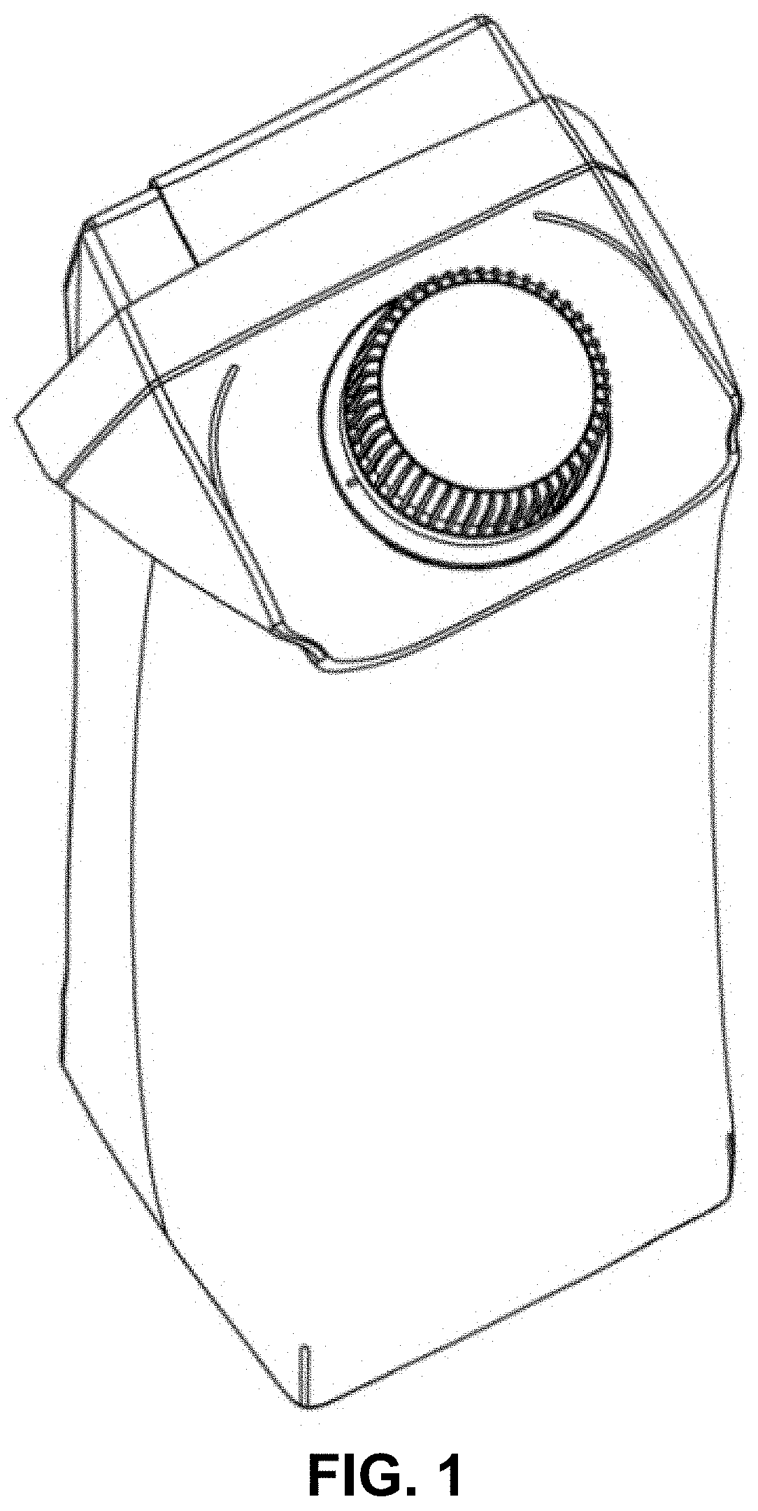
FIG. 1 is a perspective view of a beverage carton, showing our new design in accordance with a first embodiment of the present invention;
FIG. 2 is a front elevation view thereof;
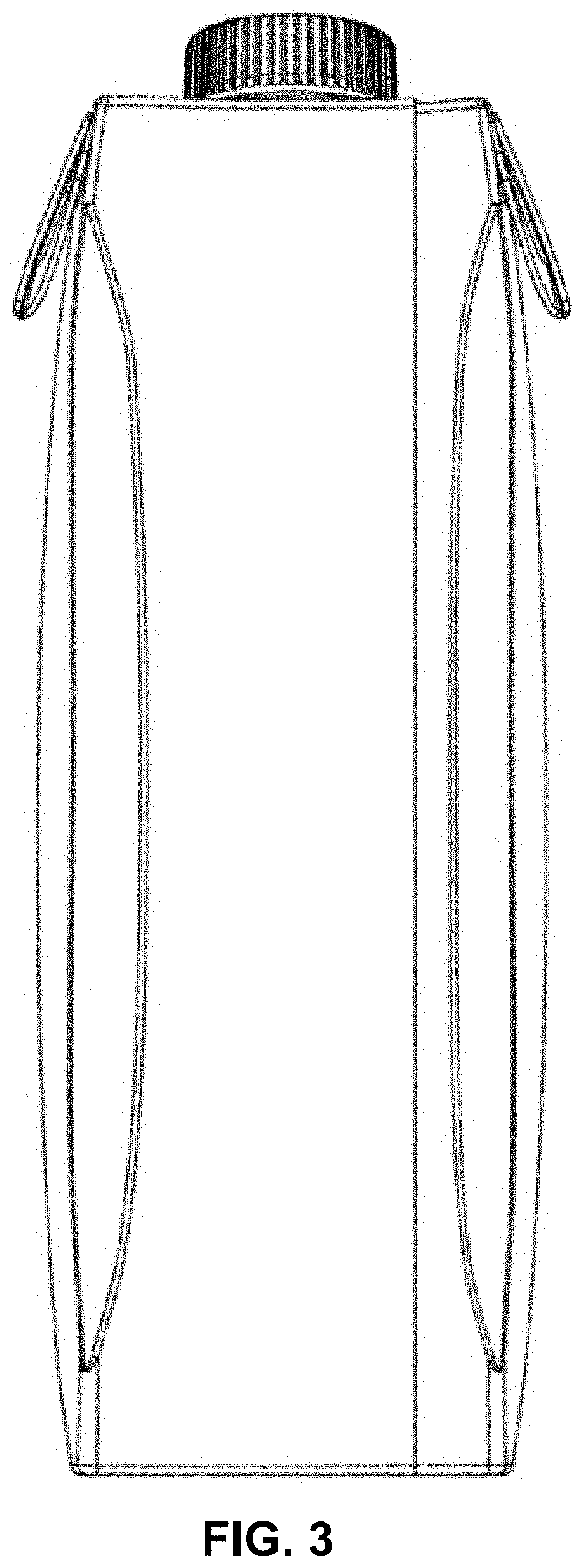
FIG. 3 is a rear elevation view thereof;
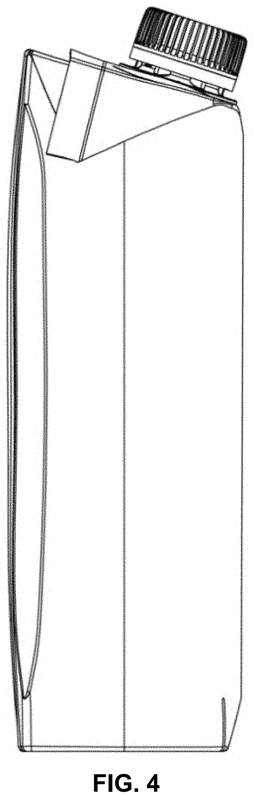
FIG. 4 is a left side elevation view thereof;
FIG. 5 is a right side elevation view thereof;
FIG. 6 is a top view thereof;
FIG. 7 is a bottom view thereof;
FIG. 8 is a perspective view of a beverage carton, showing our new design in accordance with a second embodiment of the present invention;
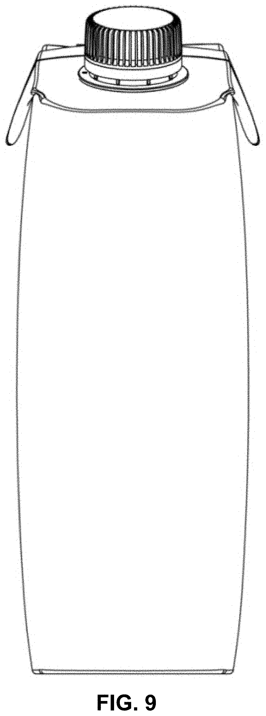
FIG. 9 is a front elevation view thereof;
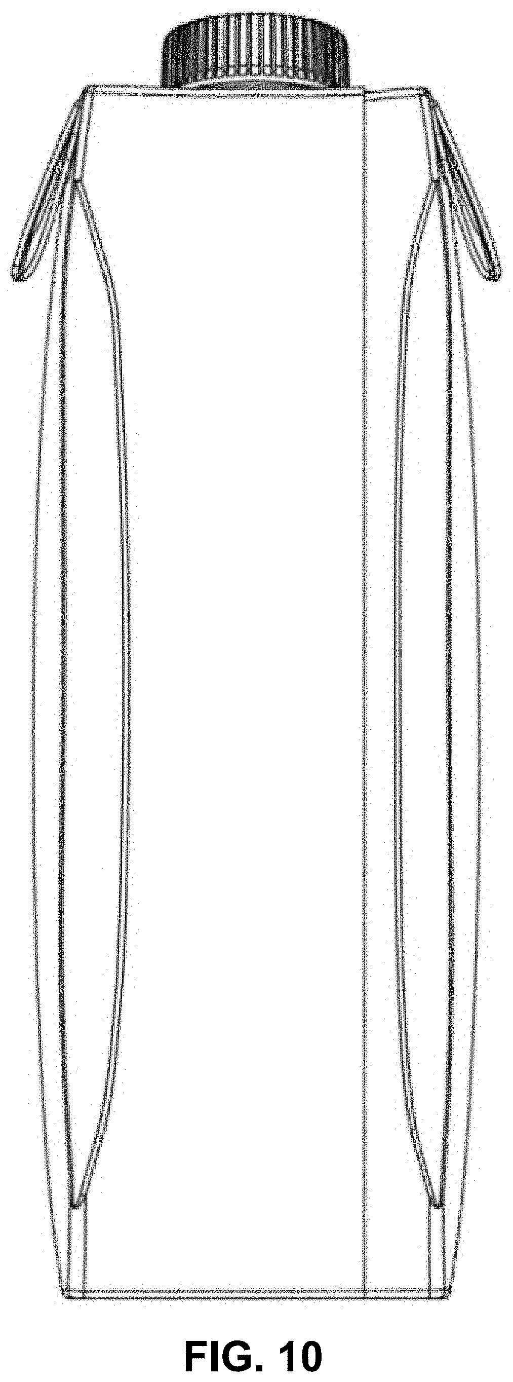
FIG. 10 is a rear elevation view thereof;
FIG. 11 is a left side elevation view thereof;
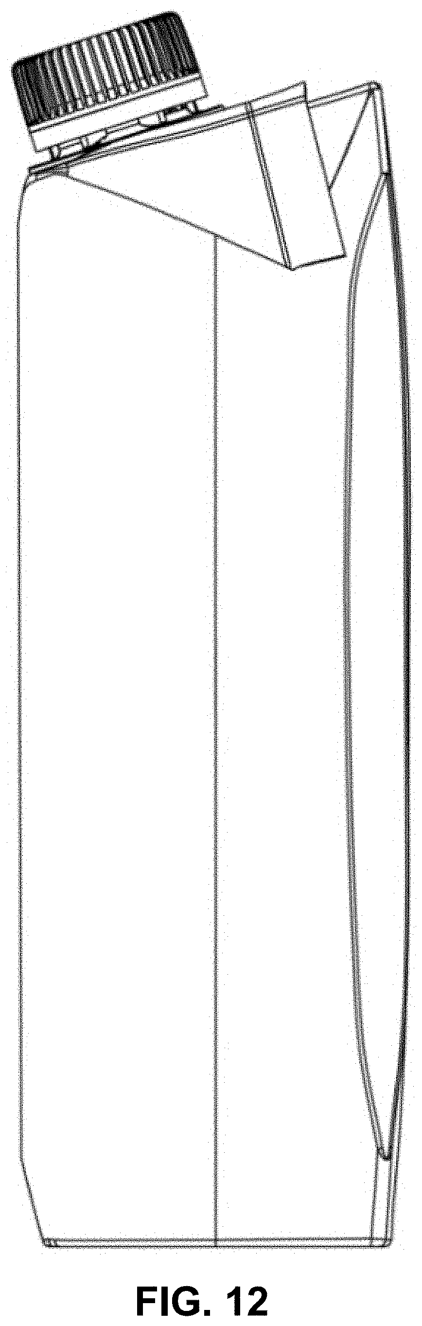
FIG. 12 is a right side elevation view thereof;
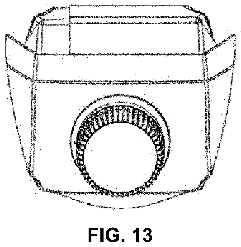
FIG. 13 is a top view thereof; and,
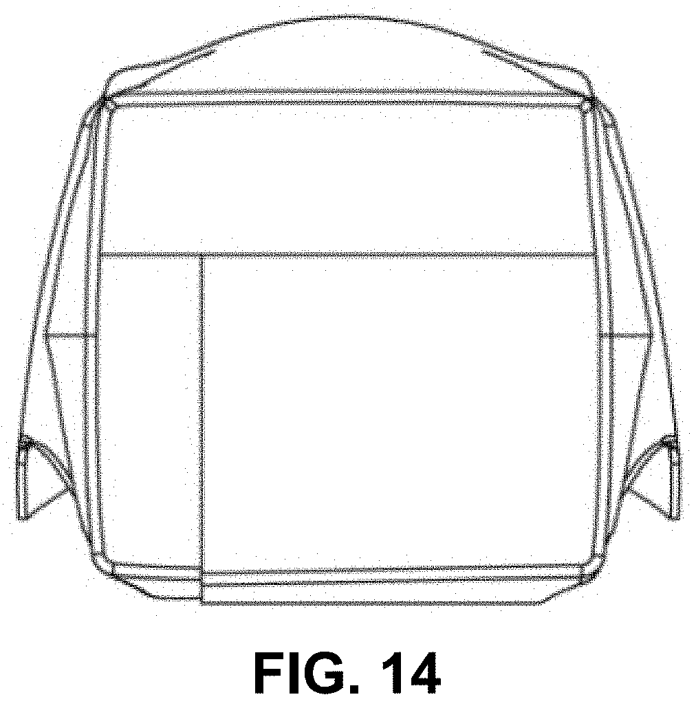
FIG. 14 is a bottom view thereof.
* * * * *
D00000
D00001
D00002
D00003
D00004
D00005
D00006
D00007
D00008
D00009
D00010
D00011
D00012
D00013
D00014
XML
uspto.report is an independent third-party trademark research tool that is not affiliated, endorsed, or sponsored by the United States Patent and Trademark Office (USPTO) or any other governmental organization. The information provided by uspto.report is based on publicly available data at the time of writing and is intended for informational purposes only.
While we strive to provide accurate and up-to-date information, we do not guarantee the accuracy, completeness, reliability, or suitability of the information displayed on this site. The use of this site is at your own risk. Any reliance you place on such information is therefore strictly at your own risk.
All official trademark data, including owner information, should be verified by visiting the official USPTO website at www.uspto.gov. This site is not intended to replace professional legal advice and should not be used as a substitute for consulting with a legal professional who is knowledgeable about trademark law.