Imaging apparatus
Li , et al. May 11, 2
U.S. patent number D919,090 [Application Number D/682,357] was granted by the patent office on 2021-05-11 for imaging apparatus. This patent grant is currently assigned to GE PRECISION HEALTHCARE LLC. The grantee listed for this patent is GE Precision Healthcare LLC. Invention is credited to Samuel Lee Alder, David Barker, Jundong Li, Tie Chang Liu.


View All Diagrams
| United States Patent | D919,090 |
| Li , et al. | May 11, 2021 |
Imaging apparatus
Claims
CLAIM The ornamental design for an imaging apparatus, as shown and described.
| Inventors: | Li; Jundong (Beijing, CN), Alder; Samuel Lee (Stansbury Park, UT), Liu; Tie Chang (Beijing, CN), Barker; David (Salt Lake City, UT) | ||||||||||
|---|---|---|---|---|---|---|---|---|---|---|---|
| Applicant: |
|
||||||||||
| Assignee: | GE PRECISION HEALTHCARE LLC
(Milwaukie, WI) |
||||||||||
| Appl. No.: | D/682,357 | ||||||||||
| Filed: | March 4, 2019 |
| Current U.S. Class: | D24/158 |
| Current International Class: | 2401 |
| Field of Search: | ;D24/158-160,107,185,186 |
References Cited [Referenced By]
U.S. Patent Documents
| D366701 | January 1996 | Mazess et al. |
| 6142667 | November 2000 | Pattee |
| D648028 | November 2011 | Yokoyama |
| D658762 | May 2012 | Yokoyama |
| D702837 | April 2014 | Dinse |
| D735863 | August 2015 | Doerre |
| D796043 | August 2017 | Boehner |
| D836779 | December 2018 | Alder et al. |
| D868260 | November 2019 | Achleitner |
| D884182 | May 2020 | Horndler |
| 2008/0123819 | May 2008 | Jensen |
| 2018/0296174 | October 2018 | Barker |
Attorney, Agent or Firm: McCoy Russell LLP
Description
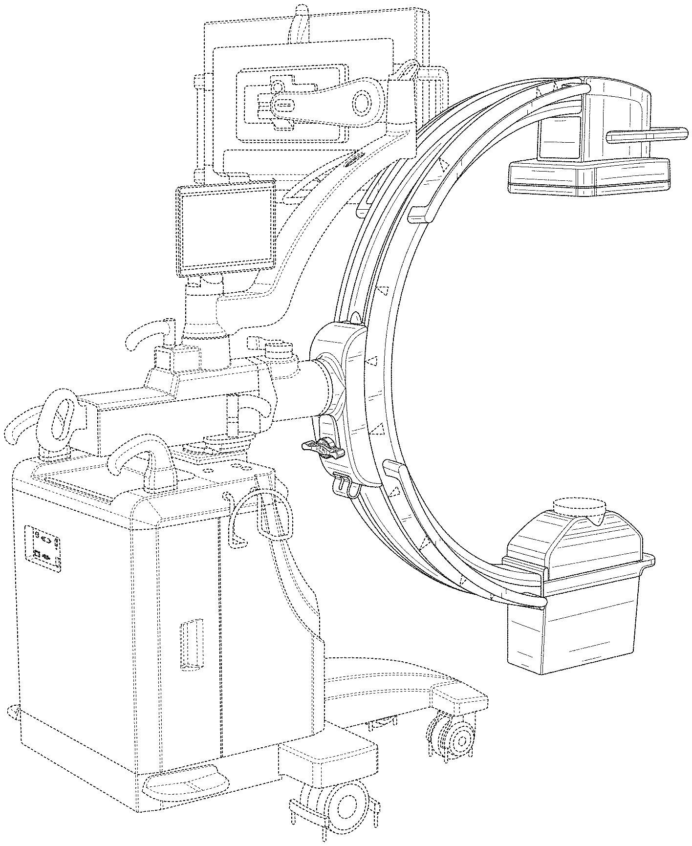
FIG. 1 is a rear-right perspective view of an imaging apparatus according to the present invention.
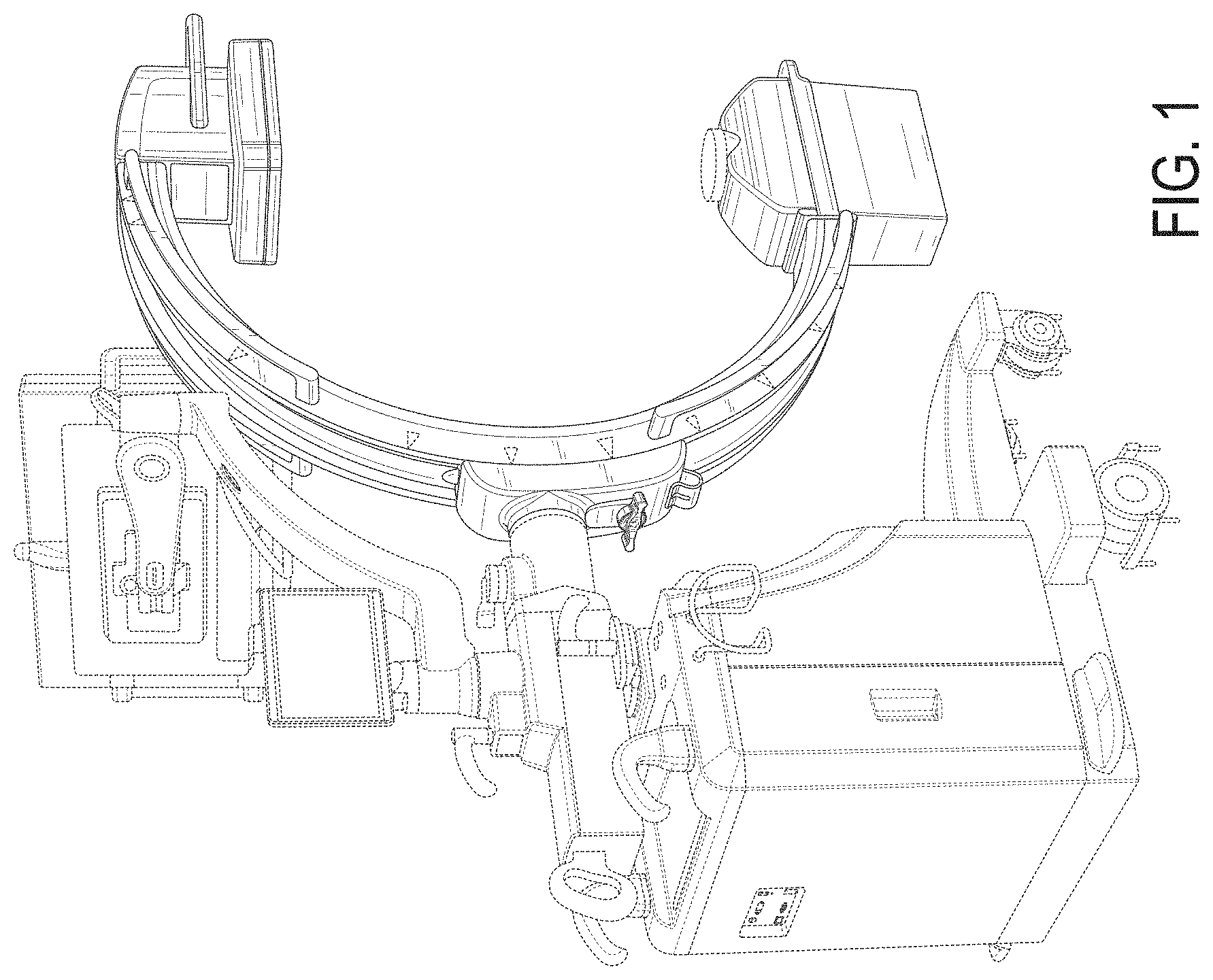
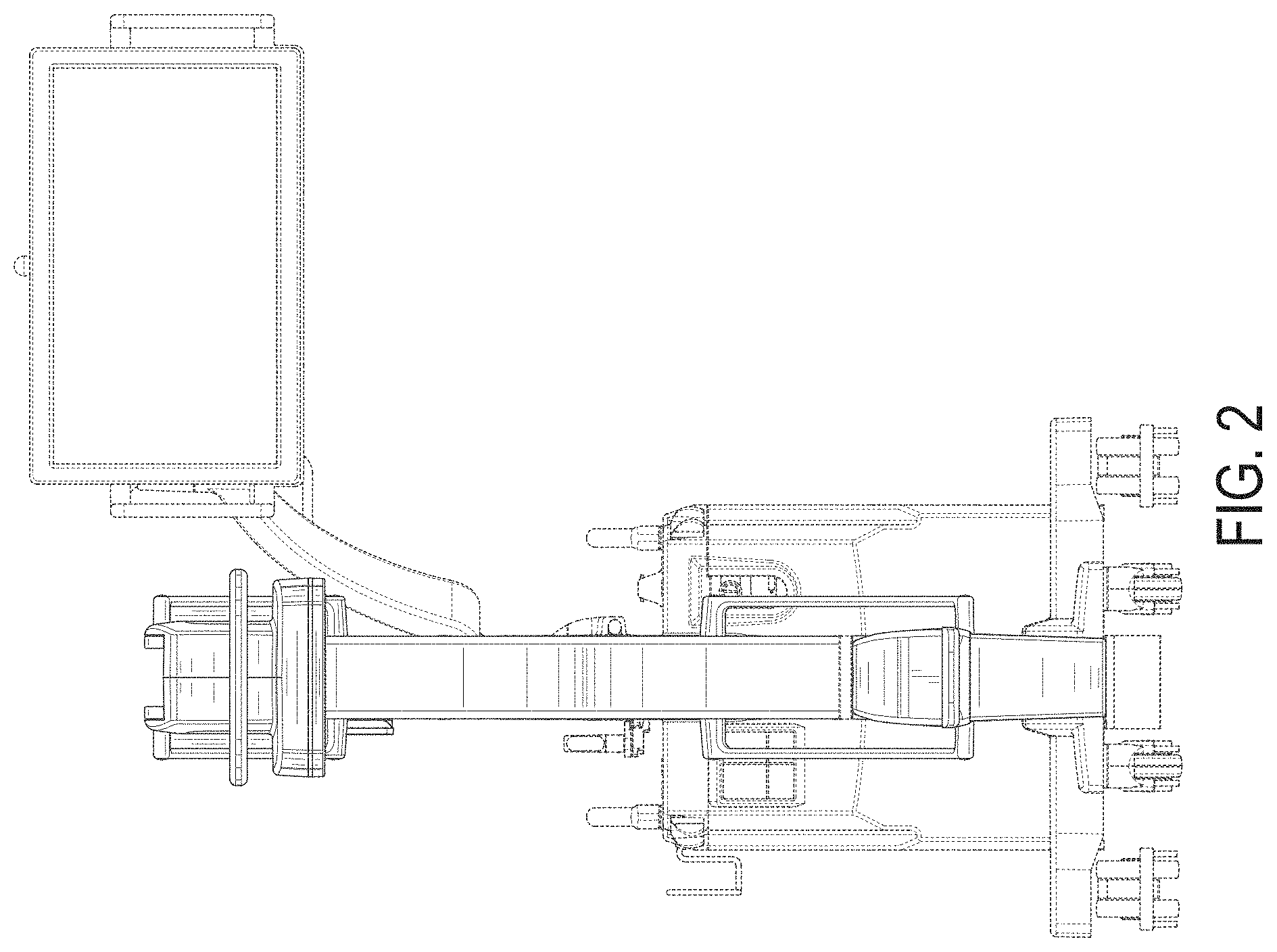
FIG. 2 is a front view of the imaging apparatus.
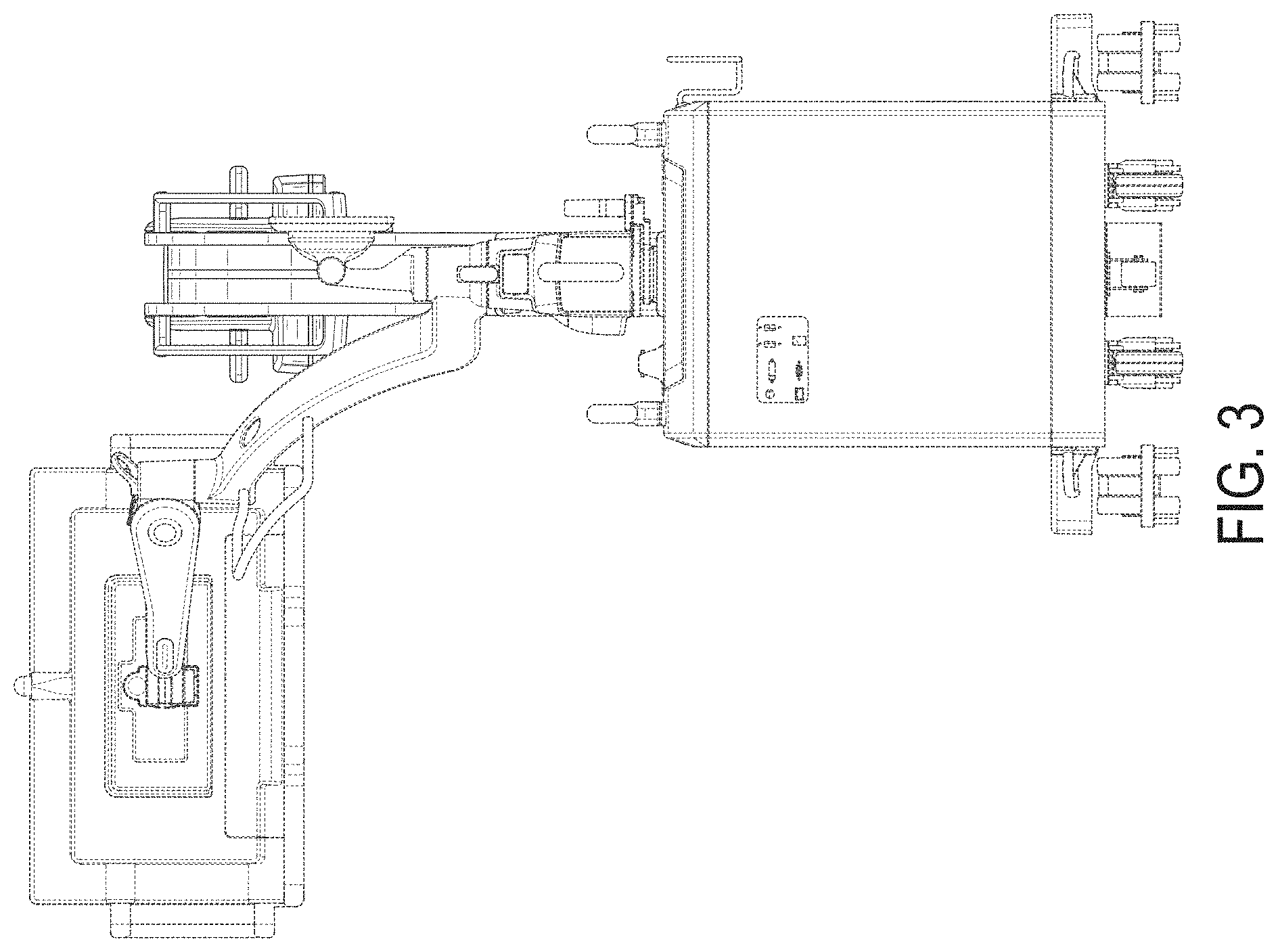
FIG. 3 is a rear view of the imaging apparatus.
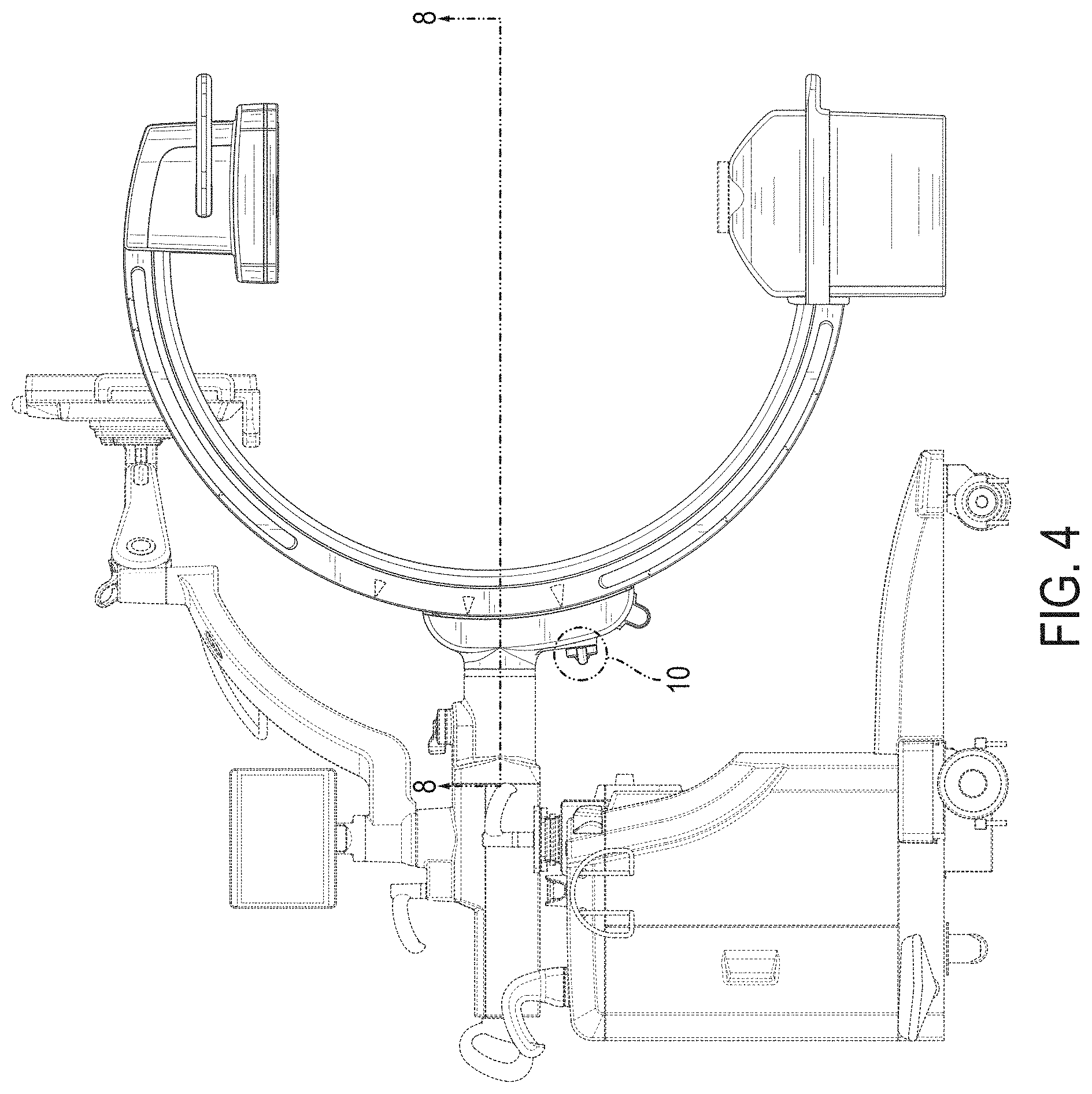
FIG. 4 is a right side view of the imaging apparatus.
FIG. 5 is a left side view of the imaging apparatus.
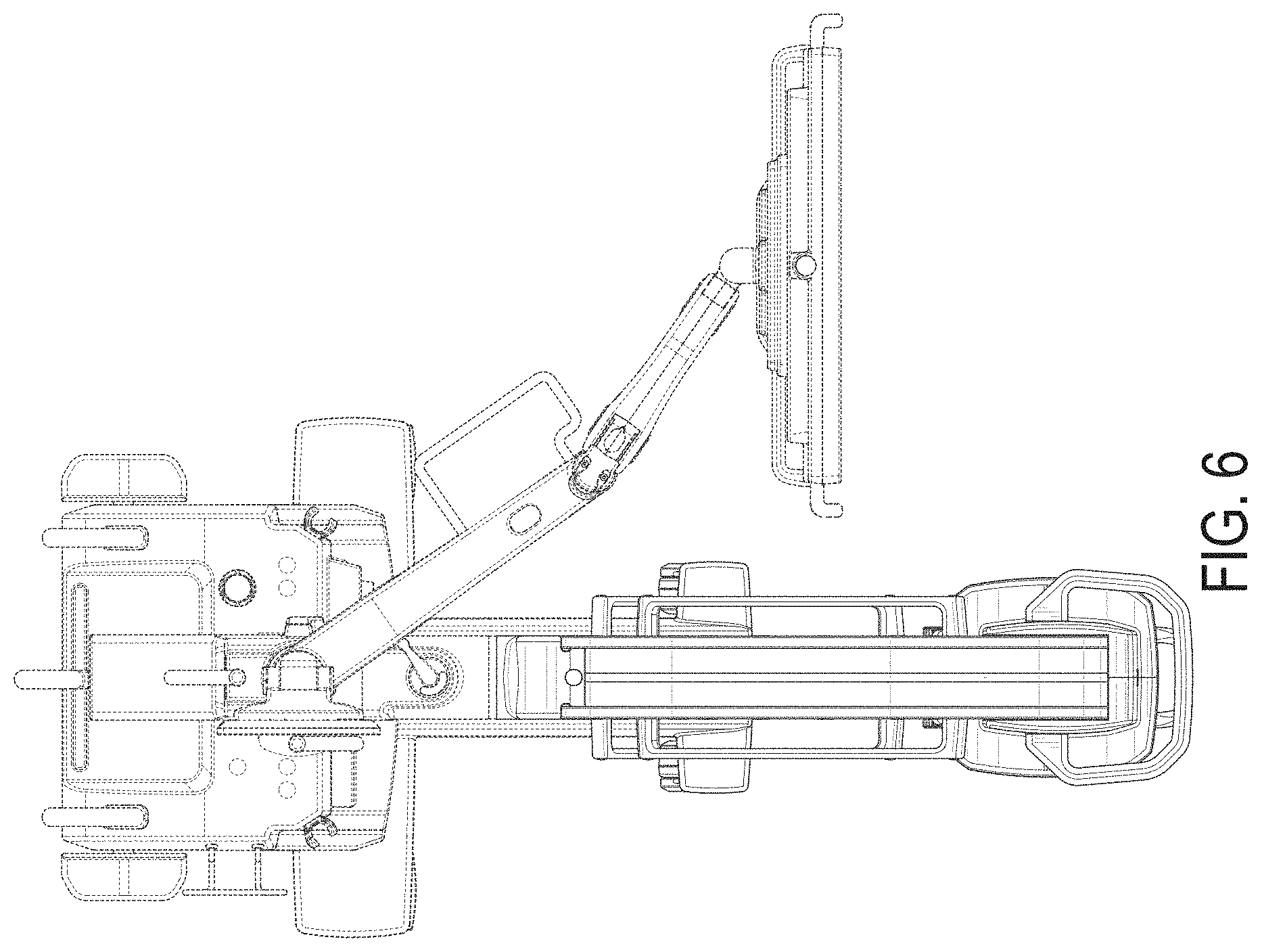
FIG. 6 is a top view of the imaging apparatus.
FIG. 7 is a bottom view of the imaging apparatus.
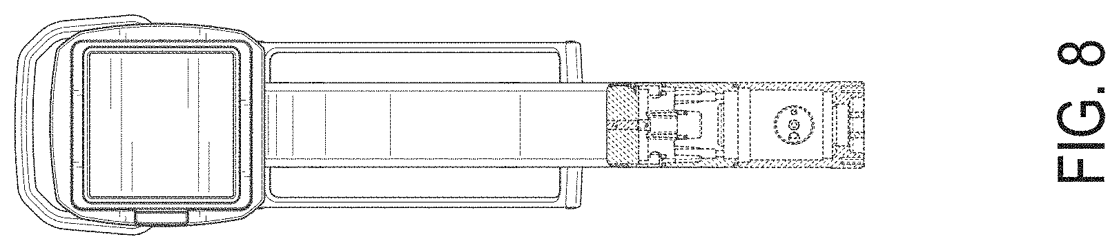
FIG. 8 is a sectional view of the imaging apparatus along 8-8 in FIG. 4.
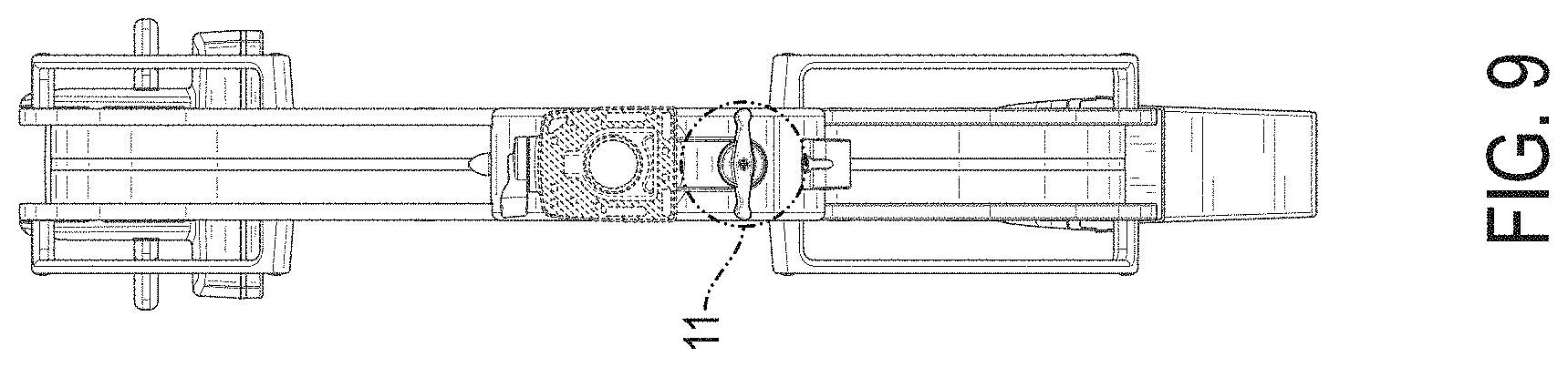
FIG. 9 is a sectional view of the imaging apparatus along 9-9 in FIG. 5.
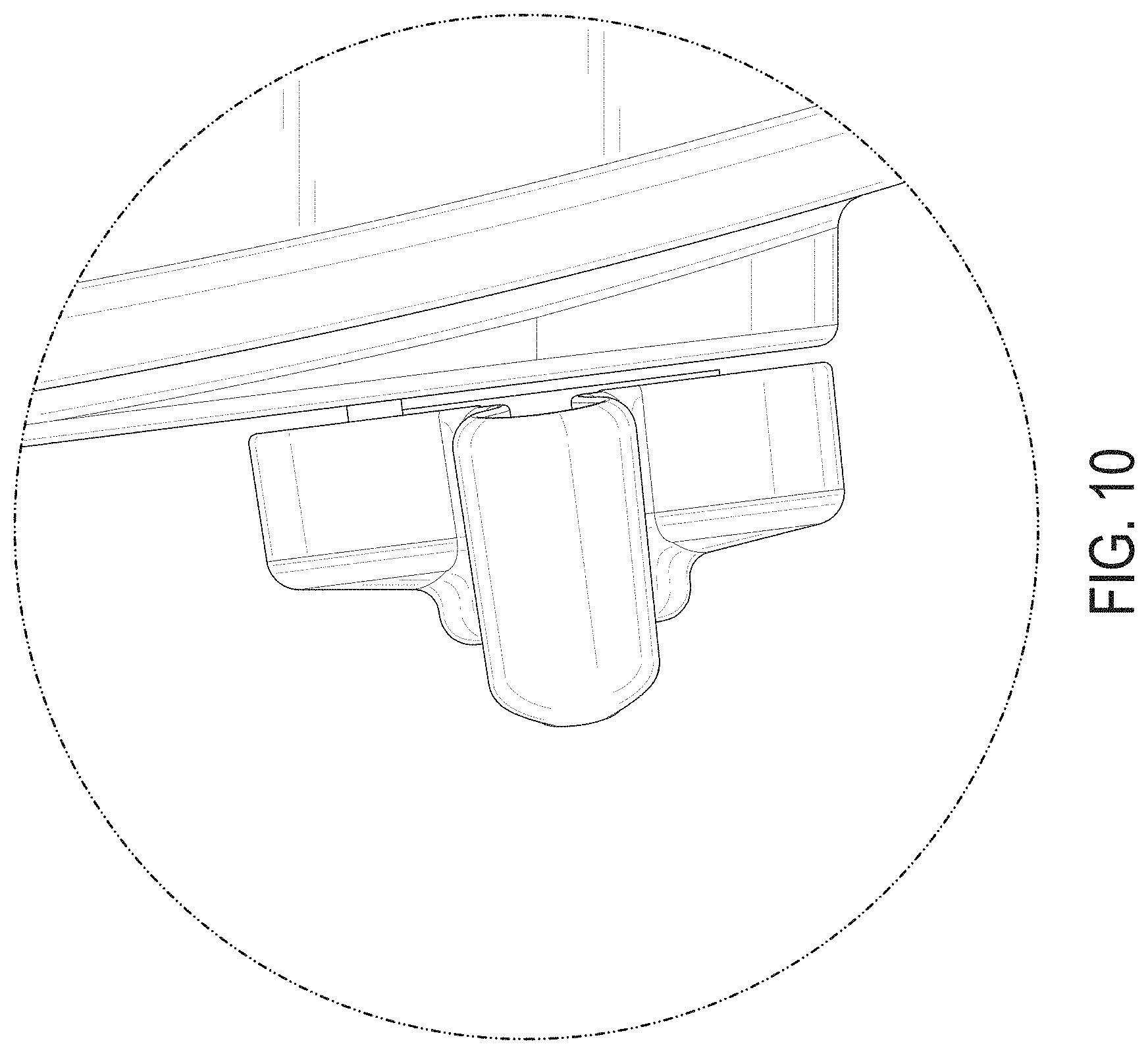
FIG. 10 is an enlarged view of the encircled portion of FIG. 4; and,
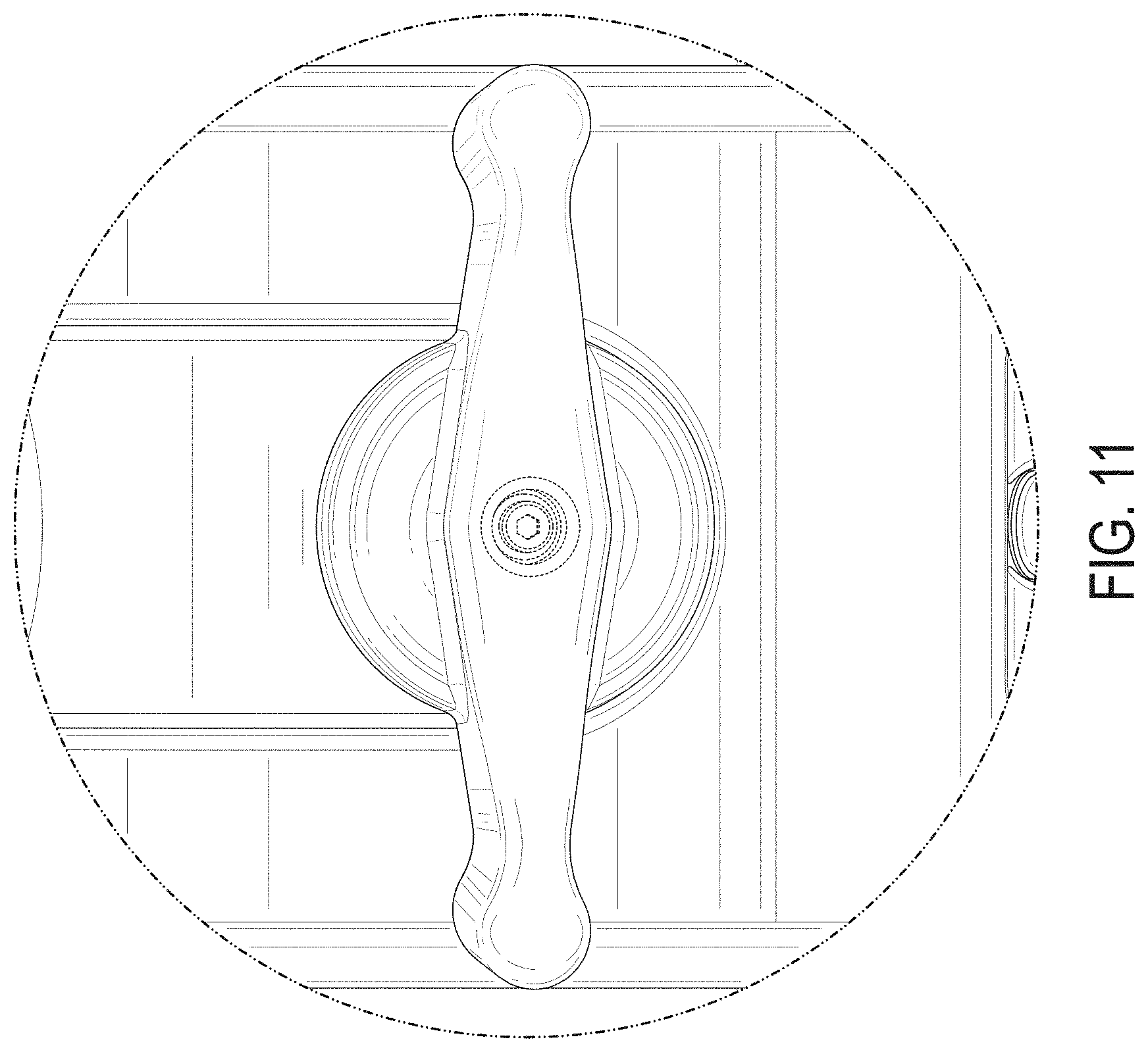
FIG. 11 is an enlarged view of the encircled portionof FIG. 9.
The dash-dash broken lines in FIGS. 1-9 illustrate portions of the imaging apparatus that form no part of the claimed design.
The dash-dot-dot-dash broken lines in FIGS. 4 and 5 showing the sectional lines and the encircled portions of the imaging apparatus form no part of the claimed design.
The right side view of the handle of the imaging apparatus shown in the enlargement of FIG. 10 is mirror symmetrical to the opposite side view thereof.
* * * * *
D00000
D00001
D00002
D00003
D00004
D00005
D00006
D00007
D00008
D00009
D00010
D00011
XML
uspto.report is an independent third-party trademark research tool that is not affiliated, endorsed, or sponsored by the United States Patent and Trademark Office (USPTO) or any other governmental organization. The information provided by uspto.report is based on publicly available data at the time of writing and is intended for informational purposes only.
While we strive to provide accurate and up-to-date information, we do not guarantee the accuracy, completeness, reliability, or suitability of the information displayed on this site. The use of this site is at your own risk. Any reliance you place on such information is therefore strictly at your own risk.
All official trademark data, including owner information, should be verified by visiting the official USPTO website at www.uspto.gov. This site is not intended to replace professional legal advice and should not be used as a substitute for consulting with a legal professional who is knowledgeable about trademark law.