Electric mosquito swatter
Qiu May 4, 2
U.S. patent number D918,333 [Application Number D/765,630] was granted by the patent office on 2021-05-04 for electric mosquito swatter. The grantee listed for this patent is Chenrong Qiu. Invention is credited to Chenrong Qiu.


| United States Patent | D918,333 |
| Qiu | May 4, 2021 |
Electric mosquito swatter
Claims
CLAIM The ornamental design for an electric mosquito swatter, as shown and described.
| Inventors: | Qiu; Chenrong (Meizhou, CN) | ||||||||||
|---|---|---|---|---|---|---|---|---|---|---|---|
| Applicant: |
|
||||||||||
| Appl. No.: | D/765,630 | ||||||||||
| Filed: | January 11, 2021 |
| Current U.S. Class: | D22/124 |
| Current International Class: | 2206 |
| Field of Search: | ;D22/124,120 ;43/112,137 ;D21/725,729 |
References Cited [Referenced By]
U.S. Patent Documents
| D518867 | April 2006 | Dow |
| D540415 | April 2007 | Zemel |
| D807984 | January 2018 | Borovicka |
| 2007/0113464 | May 2007 | Lan |
| 2009/0272026 | November 2009 | Su |
| 2010/0088947 | April 2010 | Mars |
Other References
|
Bug Zapper, Mosquito Killer Mosquitoes Lamp & Racket 2 in 1, USB Rechargeable Electric Fly Swatter Powerful Grid 3-Layer Mesh , Portable Handheld Bug Zapper Racket for Indoor and Outdoor . . . https://www.amazon.com/Mosquito-Mosquitoes- (Year: 2011). cited by examiner. |
Primary Examiner: Oliver-Garcia; Catherine R
Description
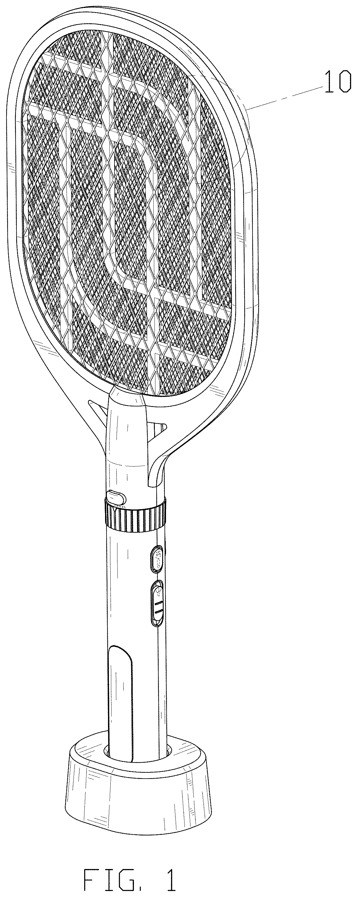
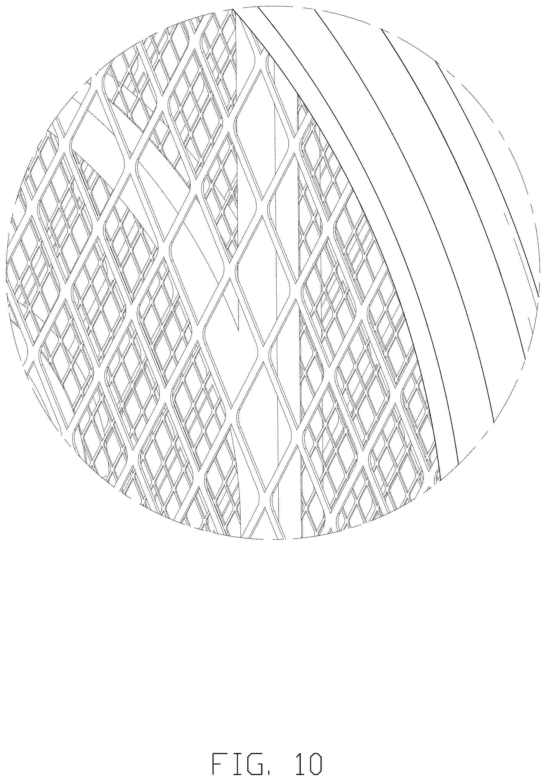
FIG. 1 is a perspective view of an electric mosquito swatter showing my new design;
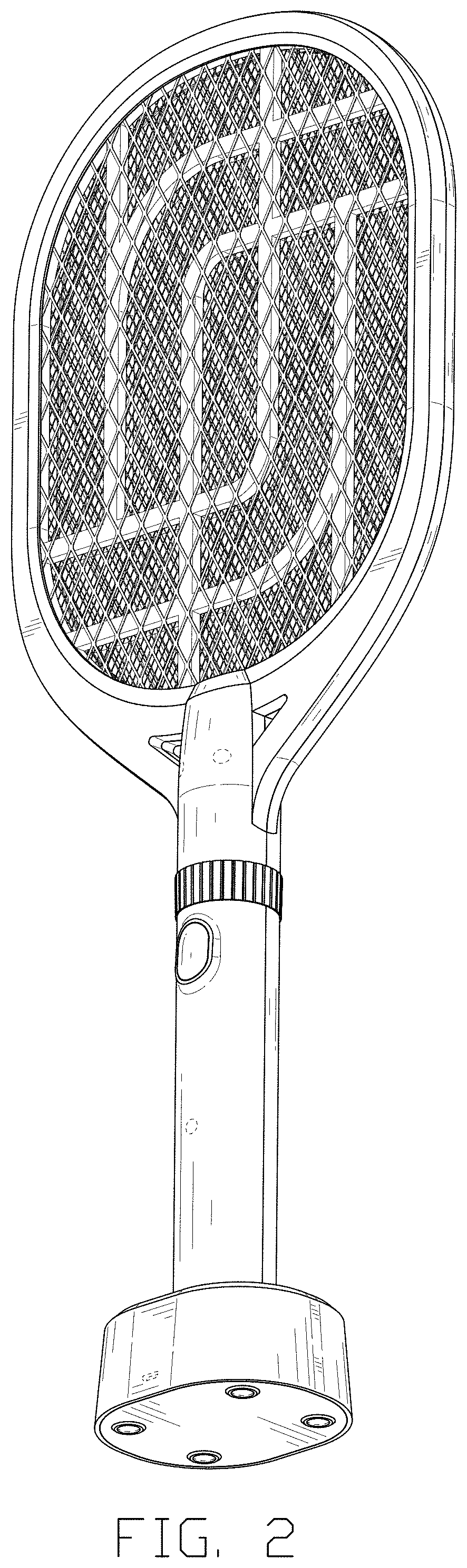
FIG. 2 is another perspective view thereof;
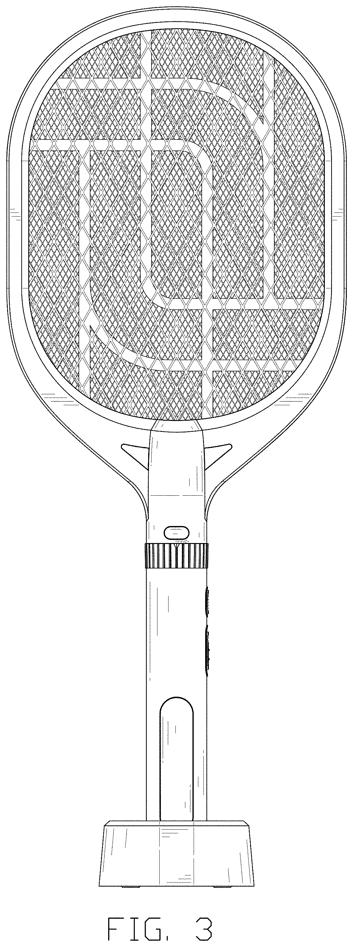
FIG. 3 is a front elevational view thereof;
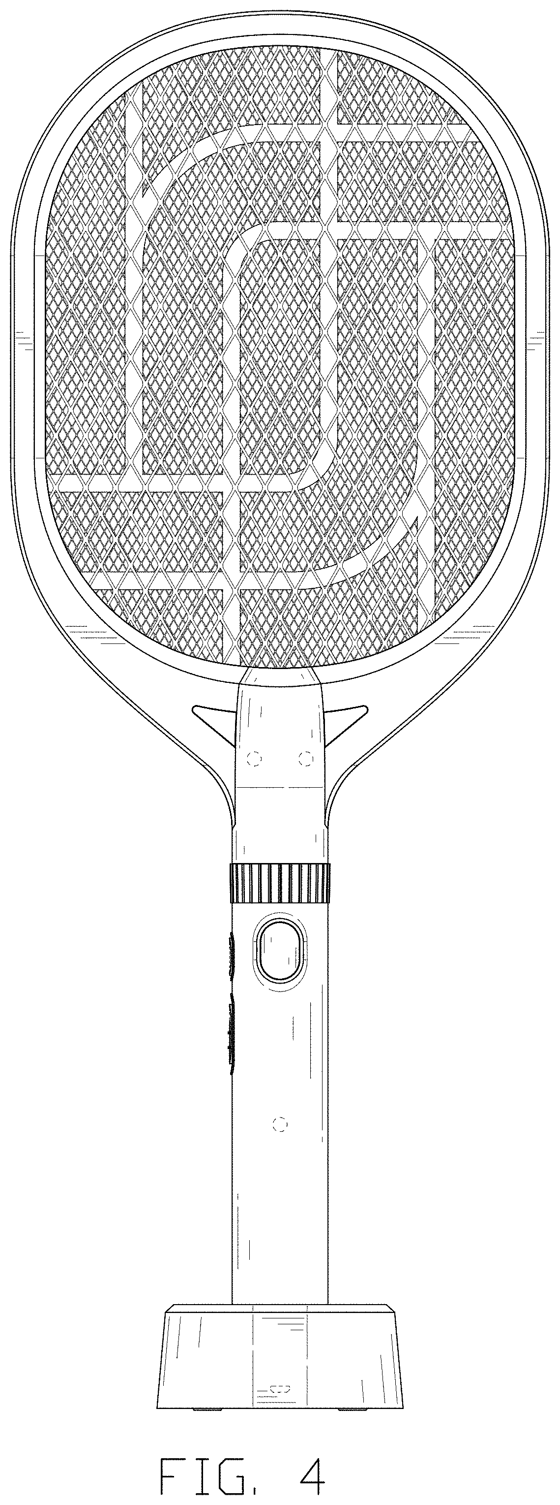
FIG. 4 is a rear elevational view thereof;
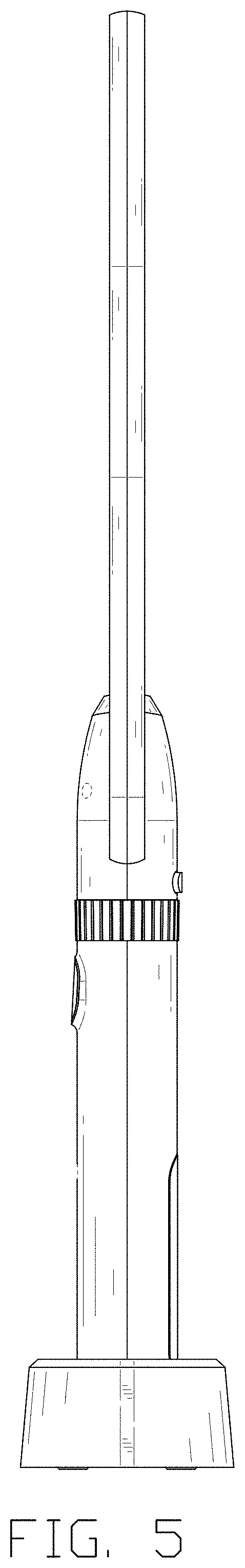
FIG. 5 is a left side elevational view thereof;
FIG. 6 is a right side elevational view thereof;
FIG. 7 is a top plan view thereof;
FIG. 8 is a bottom plan view thereof;
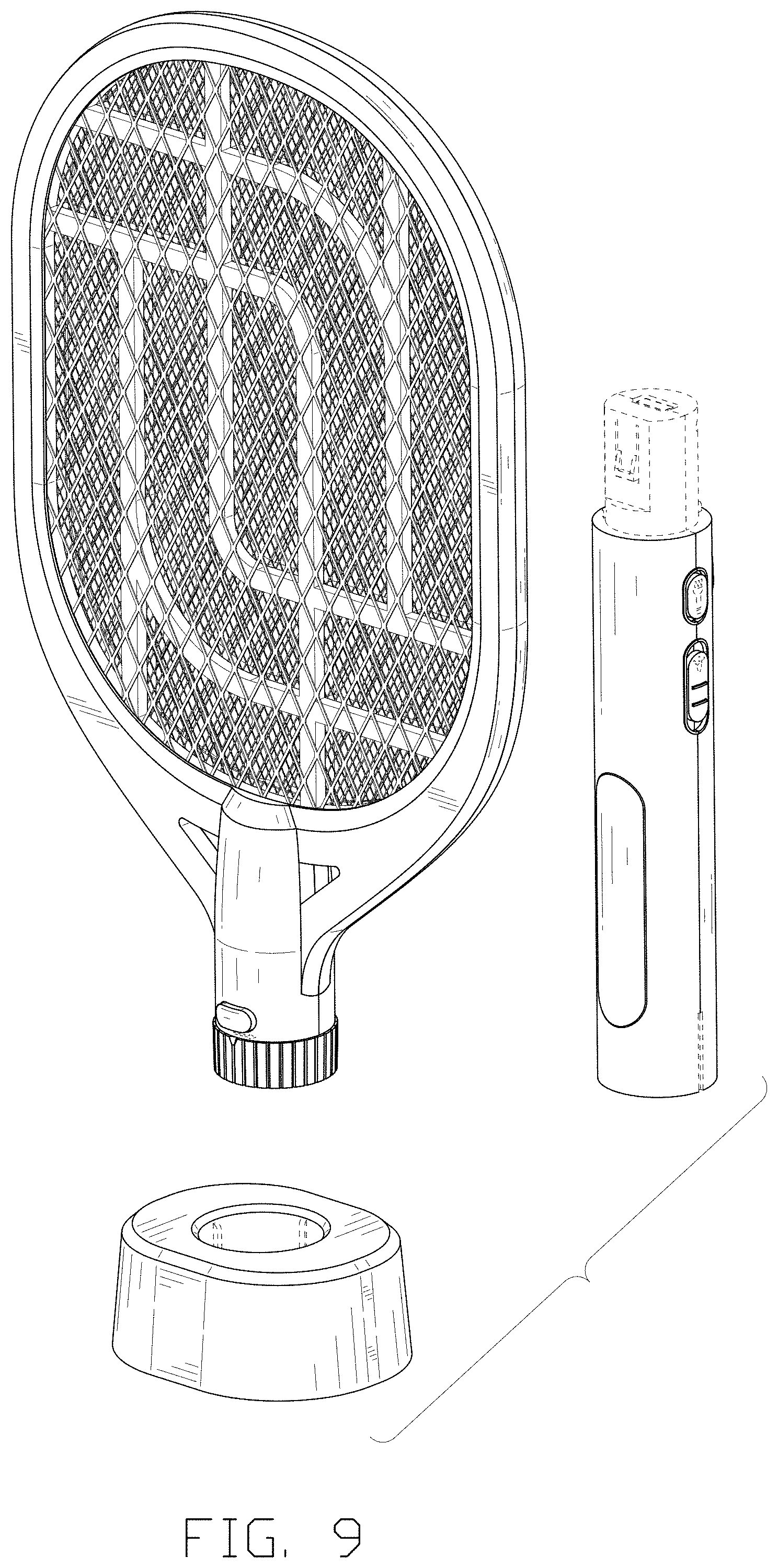
FIG. 9 is an exploded perspective view of the electric mosquito swatter; and,
FIG. 10 is an enlarged view of portion 10 shown in FIG. 1.
The broken lines in the drawings depict portions of the electric mosquito swatter that form no part of the claimed design.
* * * * *
References
D00000
D00001
D00002
D00003
D00004
D00005
D00006
D00007
D00008
D00009
D00010
XML
uspto.report is an independent third-party trademark research tool that is not affiliated, endorsed, or sponsored by the United States Patent and Trademark Office (USPTO) or any other governmental organization. The information provided by uspto.report is based on publicly available data at the time of writing and is intended for informational purposes only.
While we strive to provide accurate and up-to-date information, we do not guarantee the accuracy, completeness, reliability, or suitability of the information displayed on this site. The use of this site is at your own risk. Any reliance you place on such information is therefore strictly at your own risk.
All official trademark data, including owner information, should be verified by visiting the official USPTO website at www.uspto.gov. This site is not intended to replace professional legal advice and should not be used as a substitute for consulting with a legal professional who is knowledgeable about trademark law.