Laser impingement cooler
Sauter , et al. April 13, 2
U.S. patent number D916,149 [Application Number D/679,656] was granted by the patent office on 2021-04-13 for laser impingement cooler. This patent grant is currently assigned to PANASONIC INTELLECTUAL PROPERTY MANAGEMENT CO., LTD.. The grantee listed for this patent is PANASONIC INTELLECTUAL PROPERTY MANAGEMENT CO., LTD. Invention is credited to Bien Chann, John Kenneth Leavitt, Bryan Lochman, Matthew Sauter.
View All Diagrams
| United States Patent | D916,149 |
| Sauter , et al. | April 13, 2021 |
Laser impingement cooler
Claims
CLAIM The ornamental design for a laser impingement cooler, substantially as shown and described.
| Inventors: | Sauter; Matthew (Boston, MA), Lochman; Bryan (Somerville, MA), Leavitt; John Kenneth (Bradford, MA), Chann; Bien (Merrimack, NH) | ||||||||||
|---|---|---|---|---|---|---|---|---|---|---|---|
| Applicant: |
|
||||||||||
| Assignee: | PANASONIC INTELLECTUAL PROPERTY
MANAGEMENT CO., LTD. (Osaka, JP) |
||||||||||
| Appl. No.: | D/679,656 | ||||||||||
| Filed: | February 8, 2019 |
| Current U.S. Class: | D15/127; D15/138 |
| Current International Class: | 1509 |
| Field of Search: | ;D15/122,127 |
References Cited [Referenced By]
U.S. Patent Documents
| 5659459 | August 1997 | Wakabayashi |
| 5835345 | November 1998 | Staskus |
| 9291404 | March 2016 | Tamura |
| 2003/0131972 | July 2003 | Cosley |
| 2006/0175041 | August 2006 | Johnson |
| 2006/0243238 | November 2006 | Anezaki |
| 2009/0274176 | November 2009 | O'Shaughnessy |
| 2009/0284913 | November 2009 | Wakabayashi |
| 2011/0026551 | February 2011 | Stephens, IV |
| 2012/0177073 | July 2012 | Stephens, IV |
| 2014/0041612 | February 2014 | Furutani |
| 2016/0028210 | January 2016 | O'Shaughnessy |
| 2016/0094009 | March 2016 | Izumiya |
| 2017/0250516 | August 2017 | Kiyosawa |
| 2018/0269656 | September 2018 | Hagita |
Attorney, Agent or Firm: Morgan, Lewis & Bockius LLP
Description
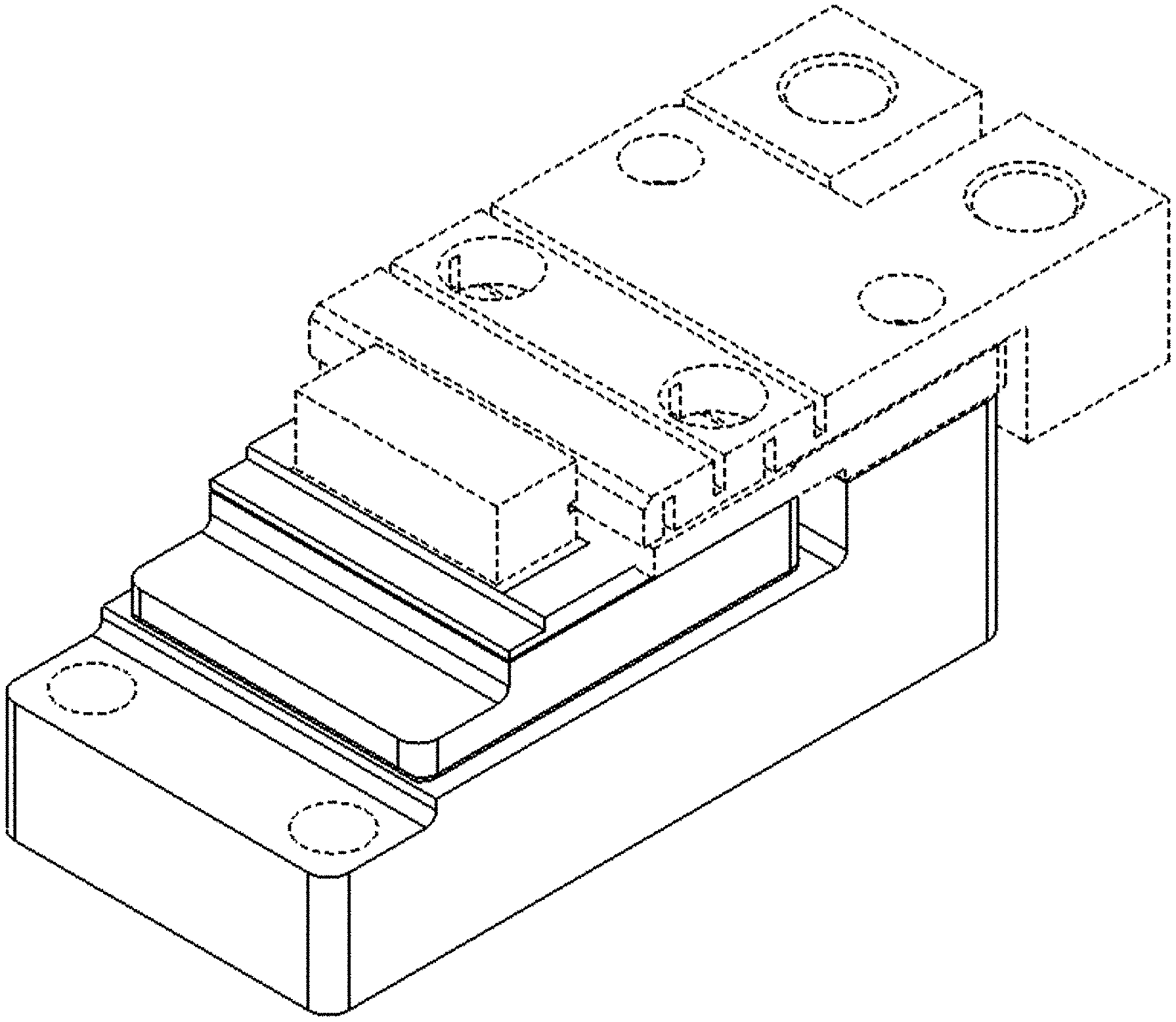
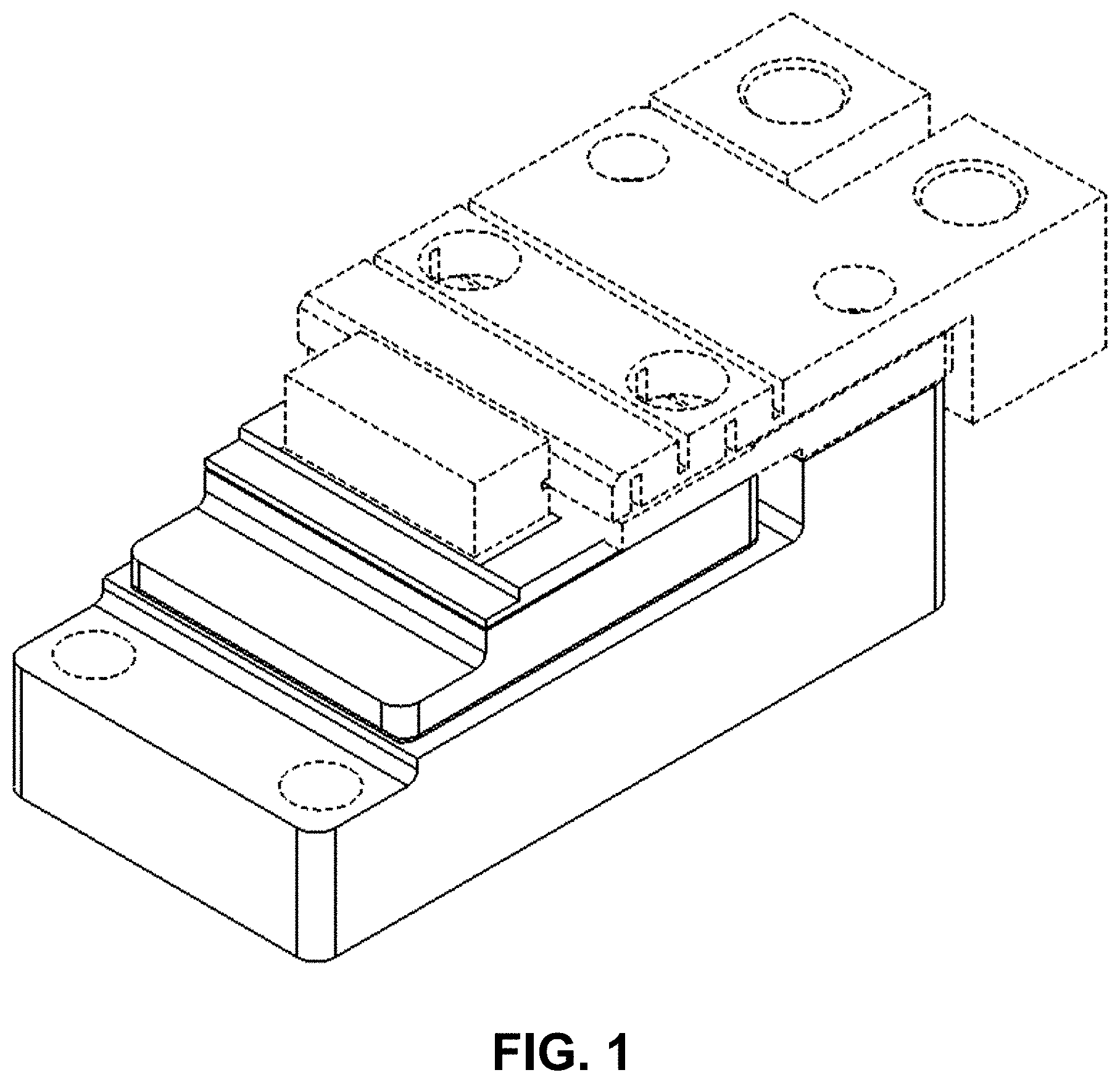
FIG. 1 is a perspective view of a laser impingement cooler incorporating the design and depicting optional electrode contacts in broken lines;
FIG. 2 is a front view of the embodiment of FIG. 1;
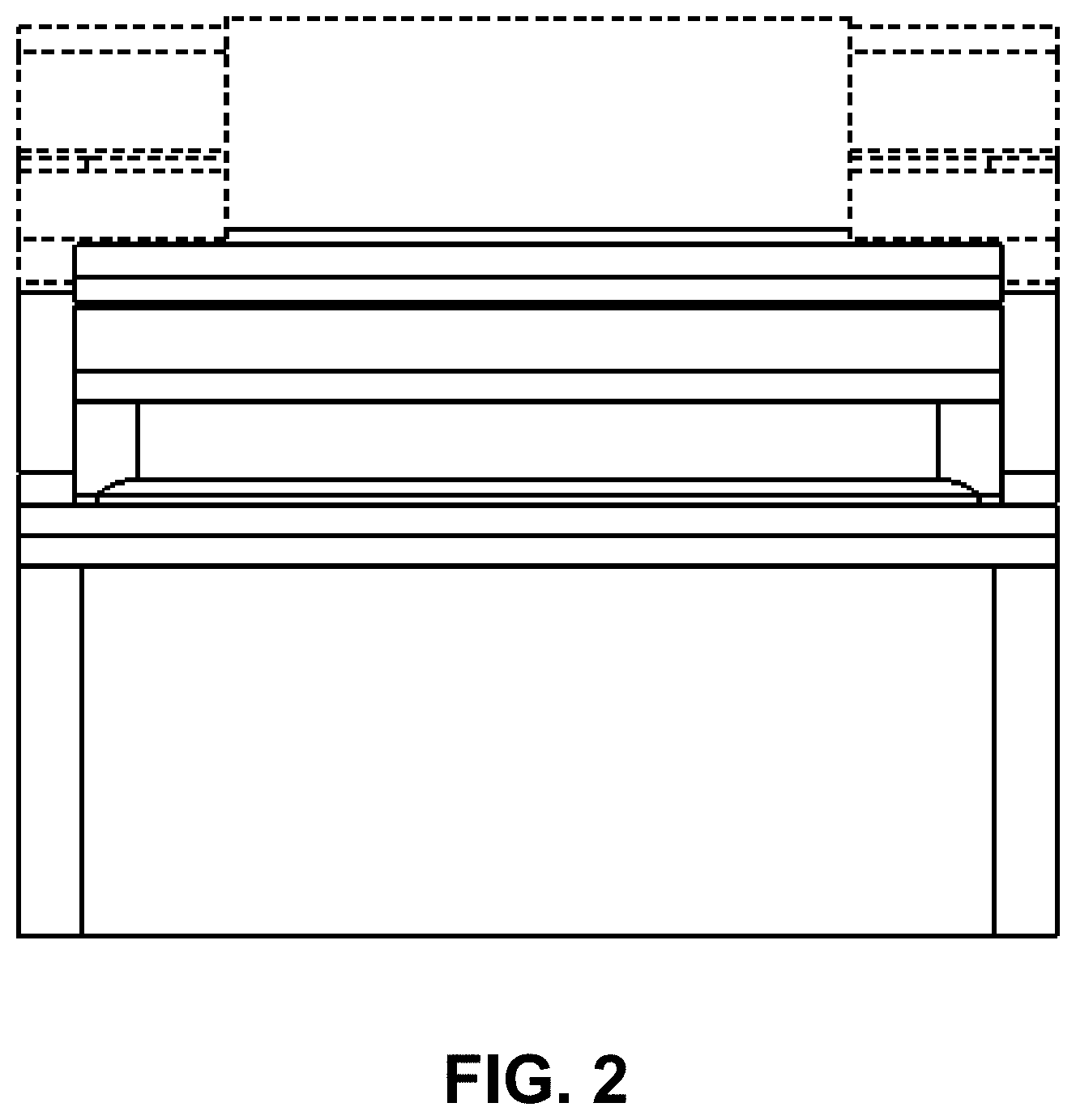
FIG. 3 is a back view of the embodiment of FIG. 1;
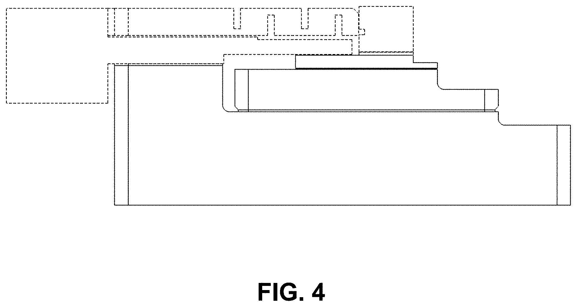
FIG. 4 is a left-side elevation view of the embodiment of FIG. 1;
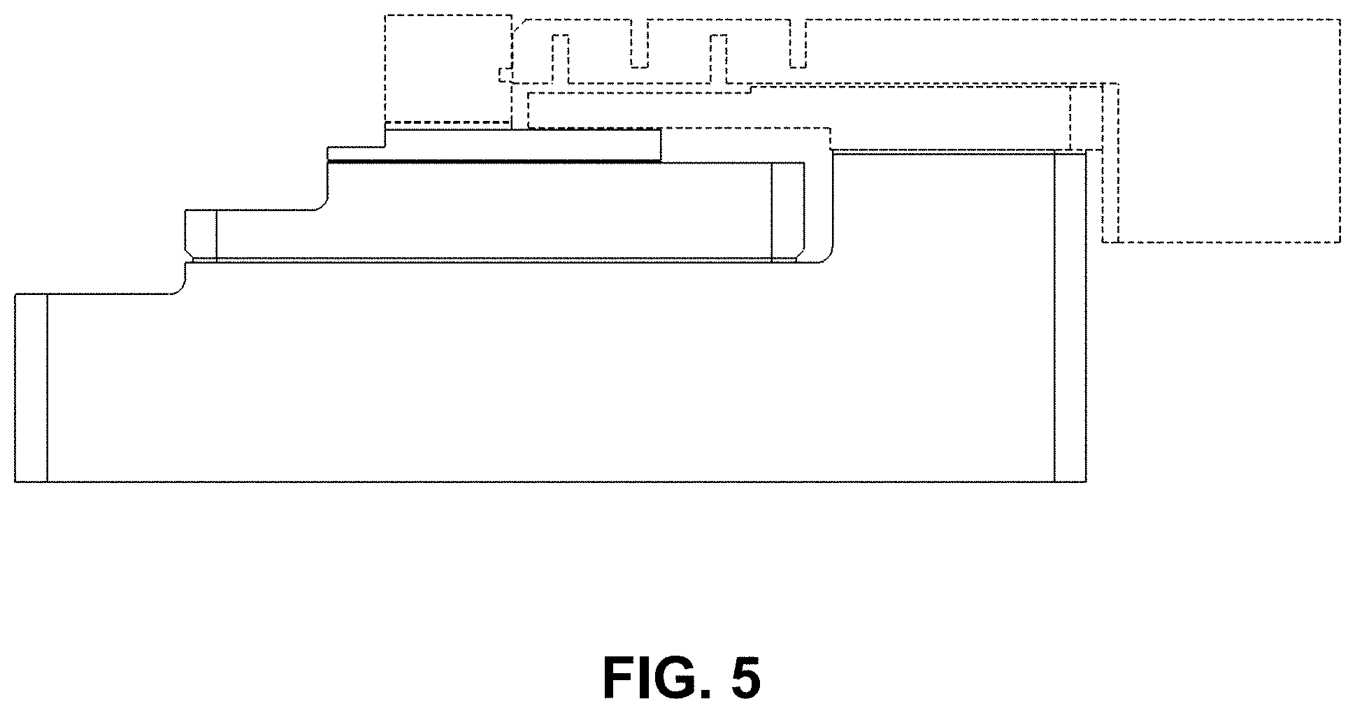
FIG. 5 is a right-side elevation view of the embodiment of FIG. 1;
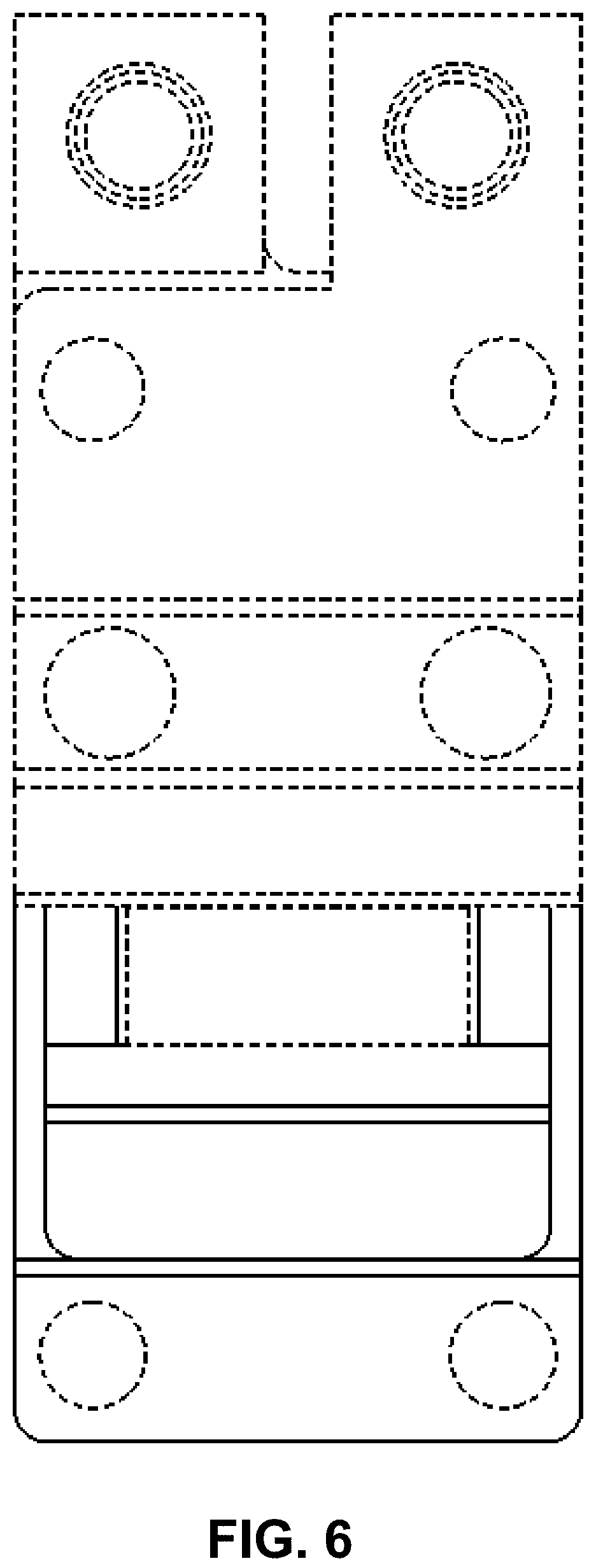
FIG. 6 is a top view of the embodiment of FIG. 1;
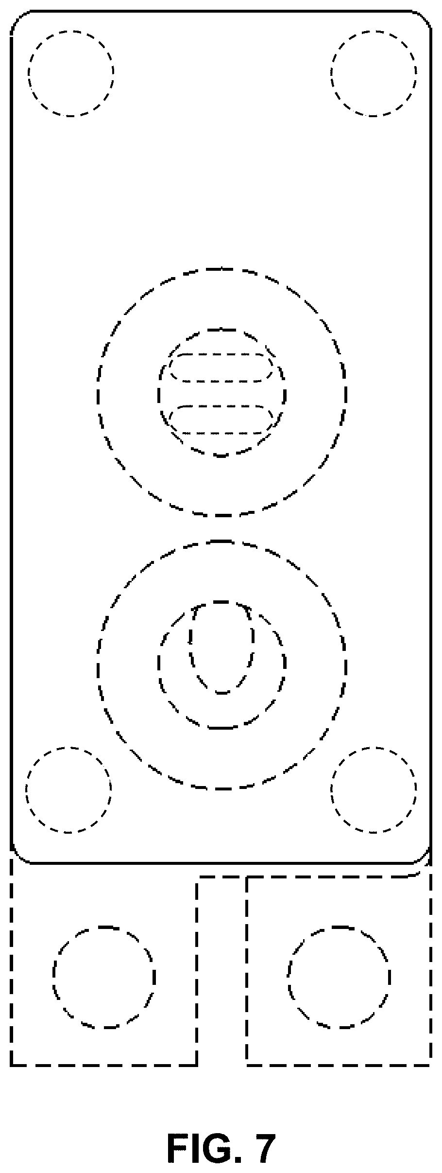
FIG. 7 is a bottom view of the embodiment of FIG. 1;
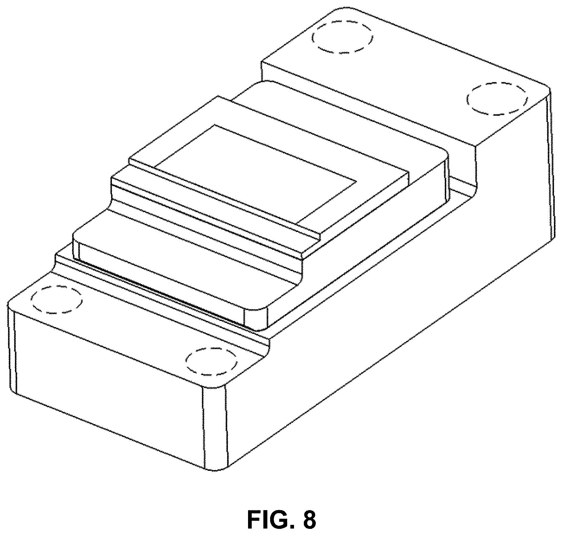
FIG. 8 is a perspective view of a laser impingement cooler incorporating the design and omitting the optional electrode contacts depicted in FIG. 1 for clarity of disclosure;
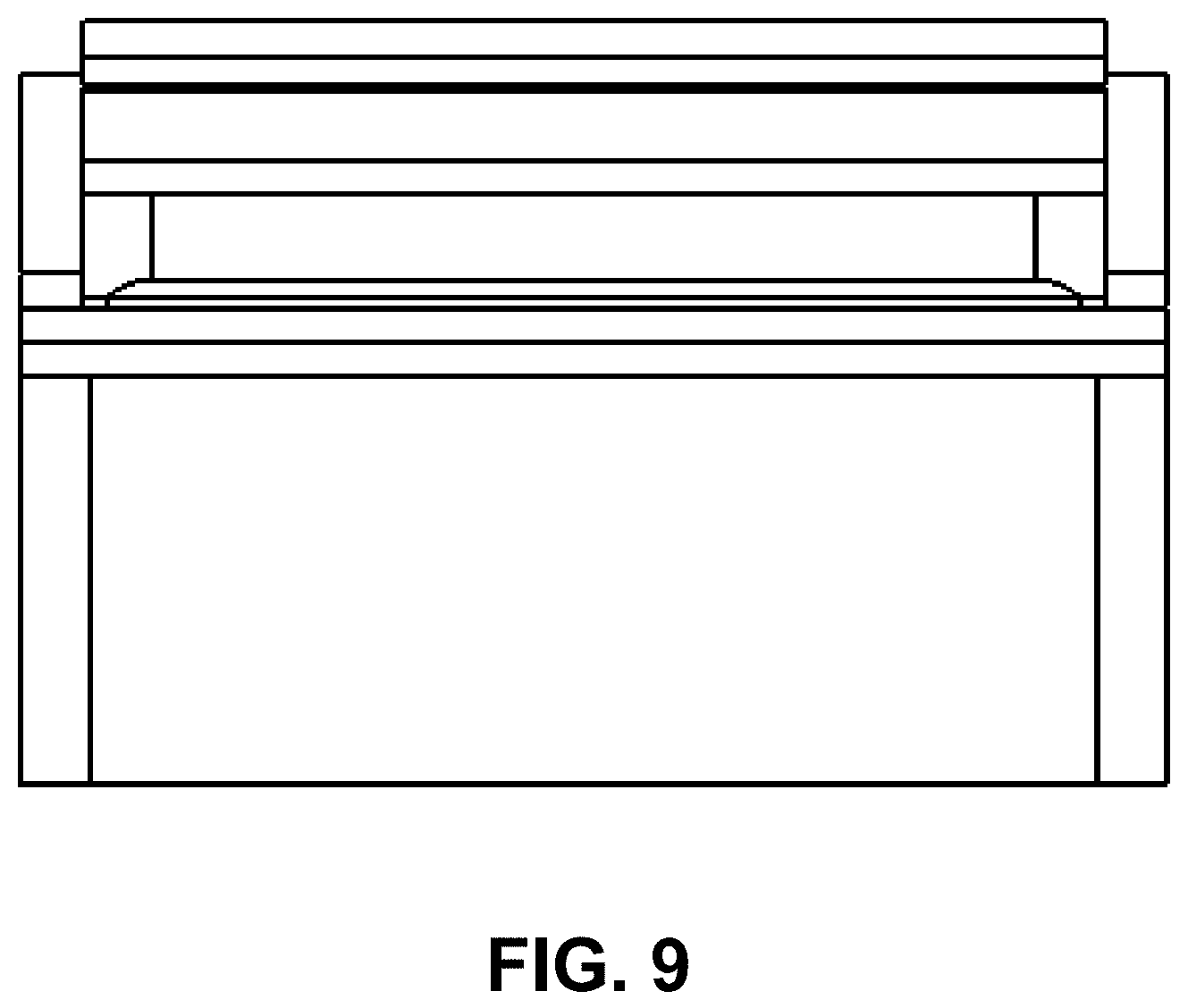
FIG. 9 is a front view of the embodiment of FIG. 8;
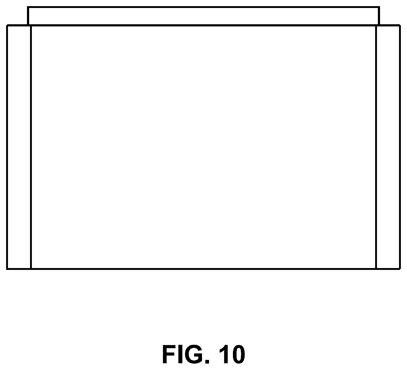
FIG. 10 is a back view of the embodiment of FIG. 8;
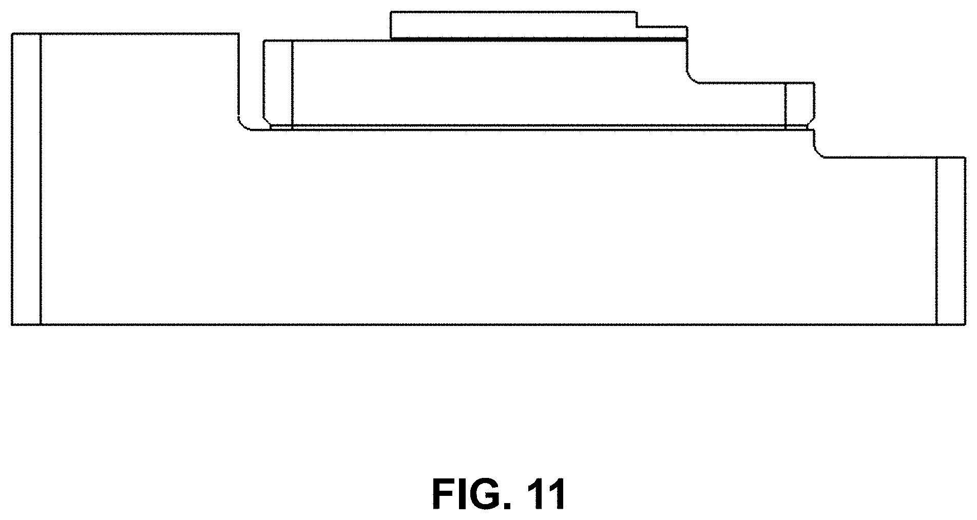
FIG. 11 is a left-side elevation view of the embodiment of FIG. 8;
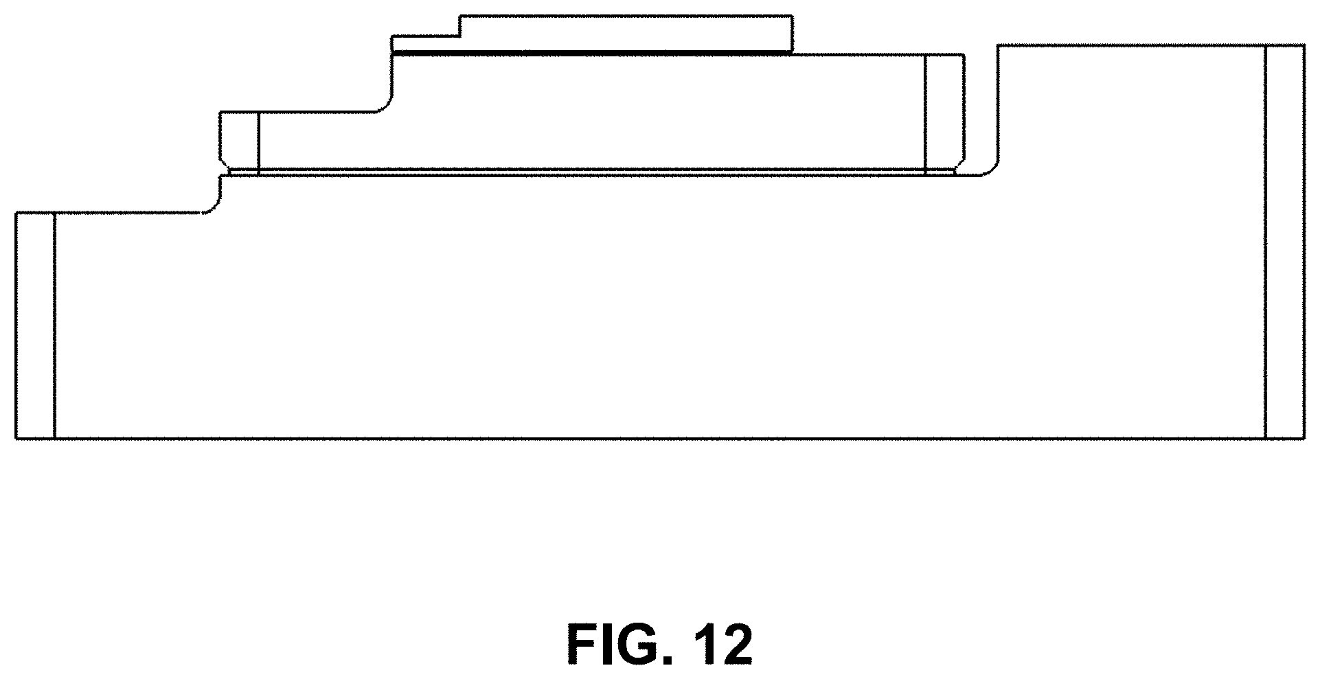
FIG. 12 is a right-side elevation view of the embodiment of FIG. 8;
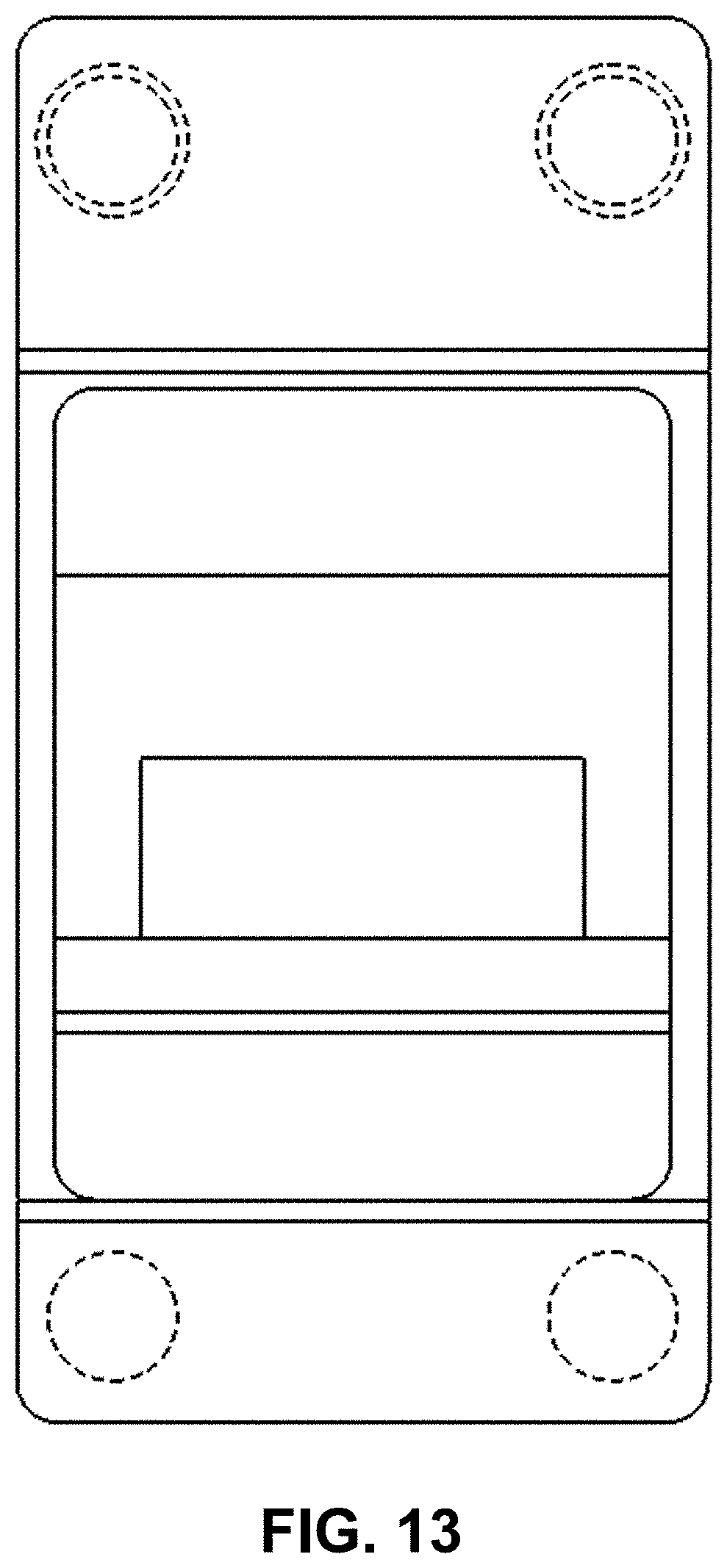
FIG. 13 is a top view of the embodiment of FIG. 8; and,
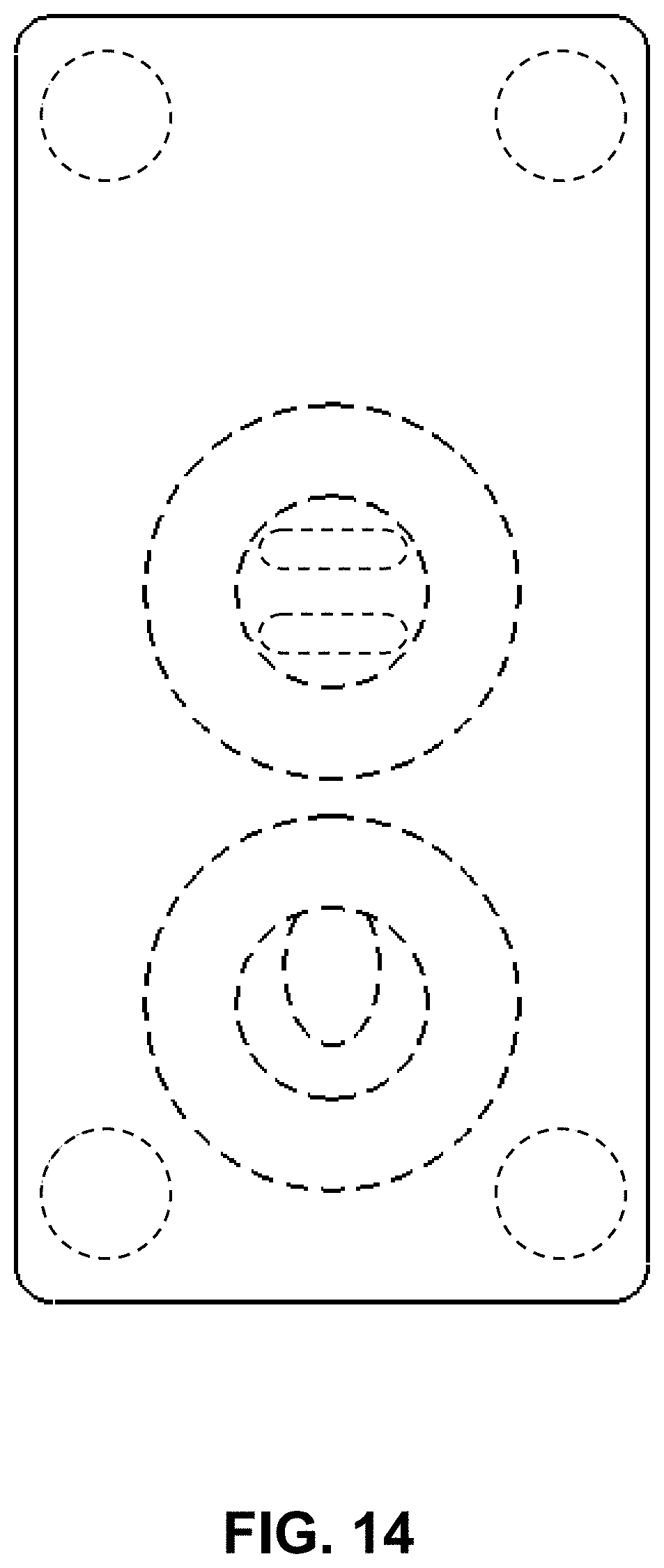
FIG. 14 is a bottom view of the embodiment of FIG. 8.
The broken lines in the drawings depict portions of the laser impingement cooler that form no part of the claimed design.
* * * * *
D00000
D00001
D00002
D00003
D00004
D00005
D00006
D00007
D00008
D00009
D00010
D00011
D00012
D00013
D00014
XML
uspto.report is an independent third-party trademark research tool that is not affiliated, endorsed, or sponsored by the United States Patent and Trademark Office (USPTO) or any other governmental organization. The information provided by uspto.report is based on publicly available data at the time of writing and is intended for informational purposes only.
While we strive to provide accurate and up-to-date information, we do not guarantee the accuracy, completeness, reliability, or suitability of the information displayed on this site. The use of this site is at your own risk. Any reliance you place on such information is therefore strictly at your own risk.
All official trademark data, including owner information, should be verified by visiting the official USPTO website at www.uspto.gov. This site is not intended to replace professional legal advice and should not be used as a substitute for consulting with a legal professional who is knowledgeable about trademark law.