Self-attaching electronic label holder
White , et al. April 13, 2
U.S. patent number D916,192 [Application Number D/726,892] was granted by the patent office on 2021-04-13 for self-attaching electronic label holder. This patent grant is currently assigned to K-International, Inc.. The grantee listed for this patent is K-International, Inc.. Invention is credited to Michael L. Sisko, Michael J. White.


| United States Patent | D916,192 |
| White , et al. | April 13, 2021 |
Self-attaching electronic label holder
Claims
CLAIM The ornamental design for a self-attaching electronic label holder, as shown and described.
| Inventors: | White; Michael J. (Green Lake, WI), Sisko; Michael L. (Kenosha, WI) | ||||||||||
|---|---|---|---|---|---|---|---|---|---|---|---|
| Applicant: |
|
||||||||||
| Assignee: | K-International, Inc.
(Waukegan, IL) |
||||||||||
| Appl. No.: | D/726,892 | ||||||||||
| Filed: | March 6, 2020 |
Related U.S. Patent Documents
| Application Number | Filing Date | Patent Number | Issue Date | ||
|---|---|---|---|---|---|
| 16536596 | Aug 9, 2019 | 10706749 | |||
| Current U.S. Class: | D20/43; D20/44 |
| Current International Class: | 2003 |
| Field of Search: | ;D6/325,328 ;D8/321,349,354,355,366,371,373,380,381,400 ;D20/10,42-44,99 ;D25/119 |
References Cited [Referenced By]
U.S. Patent Documents
| D141048 | May 1945 | Ketchum, Jr. |
| 6035569 | March 2000 | Nagel et al. |
| 6119990 | September 2000 | Kump et al. |
| D453798 | February 2002 | Gray |
| D473662 | April 2003 | Shaw |
| 6553702 | April 2003 | Bacnik |
| D476375 | June 2003 | Zadak |
| D485582 | January 2004 | Valiulis |
| D487115 | February 2004 | Kosir |
| 6935062 | August 2005 | Lowry et al. |
| 7455081 | November 2008 | Bacnik |
| D645095 | September 2011 | Garfinkle |
| D693483 | November 2013 | Krieger |
| D732702 | June 2015 | Gallien |
| D791360 | July 2017 | Singh |
| D791361 | July 2017 | Singh |
| D829823 | October 2018 | White |
| D830813 | October 2018 | Garfinkle |
| D853589 | July 2019 | Jackson |
| D858721 | September 2019 | Gori |
| D859140 | September 2019 | Kovacs |
| D859610 | September 2019 | Gori |
| D872884 | January 2020 | Carter |
| D874025 | January 2020 | Kittur |
| D875898 | February 2020 | Gori |
| D891904 | August 2020 | Naugler |
| D892602 | August 2020 | White |
| D899523 | October 2020 | Rollins |
| D899632 | October 2020 | Roberts |
| D902693 | November 2020 | Freeman |
| 2005/0133676 | June 2005 | Brinkman |
Other References
|
K International Catalog No. 16, p. 192--Part Nos. 107212, Published Oct. 2018. cited by applicant. |
Primary Examiner: Calabrese; Mary Ann
Assistant Examiner: Ho; Catherine
Attorney, Agent or Firm: Schiff Hardin LLP
Description
FIG. 1 is a front perspective view of a self-attaching electronic label holder in an environment of use;
FIG. 2 is a back perspective view of a self-attaching electronic label holder in an environment of use;
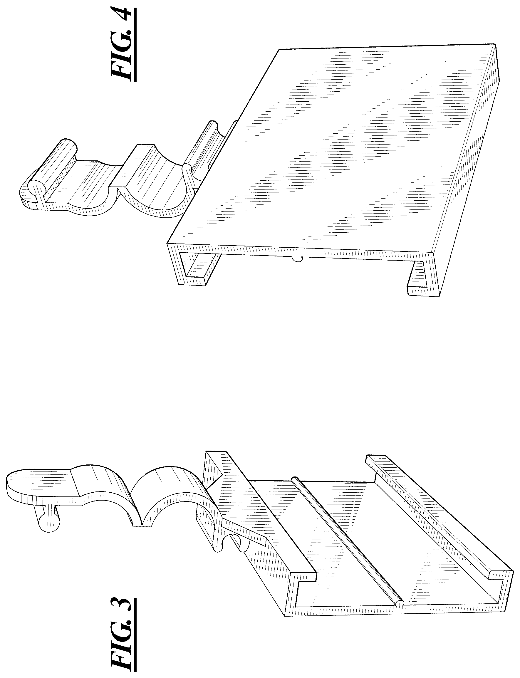
FIG. 3 is a perspective view taken from the front, top, left side of the self-attaching electronic label holder showing our new design, an attaching portion being shown in an open position;
FIG. 4 is a perspective view taken from the back, bottom, right side thereof;
FIG. 5 is a front elevational view thereof;
FIG. 6 is a back elevational view thereof;
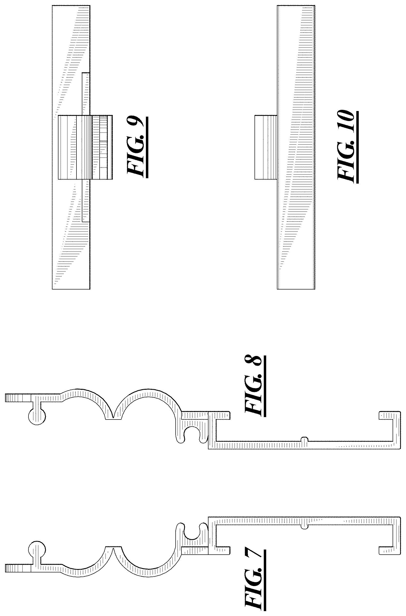
FIG. 7 is a side elevation view from the right-hand side thereof;
FIG. 8 is a side elevation view from the left-hand side thereof;
FIG. 9 is a top plan view thereof;
FIG. 10 is a bottom plan view thereof;
FIG. 11 is a perspective view from the top, front, right side of a self-attaching electronic label holder showing the attaching portion in a closed position; and,
FIG. 12 is a side elevation view from the right-hand side thereof.
The broken lines in FIGS. 1 and 2 illustrate the environment, including an electronic price label module and a wire fixture, in which the self-attaching electronic label holder may be used and form no part of the claimed design.
* * * * *
D00000
D00001
D00002
D00003
D00004
D00005
D00006
XML
uspto.report is an independent third-party trademark research tool that is not affiliated, endorsed, or sponsored by the United States Patent and Trademark Office (USPTO) or any other governmental organization. The information provided by uspto.report is based on publicly available data at the time of writing and is intended for informational purposes only.
While we strive to provide accurate and up-to-date information, we do not guarantee the accuracy, completeness, reliability, or suitability of the information displayed on this site. The use of this site is at your own risk. Any reliance you place on such information is therefore strictly at your own risk.
All official trademark data, including owner information, should be verified by visiting the official USPTO website at www.uspto.gov. This site is not intended to replace professional legal advice and should not be used as a substitute for consulting with a legal professional who is knowledgeable about trademark law.