Vertical axis wind turbine light ornament
Ashton , et al. April 6, 2
U.S. patent number D915,280 [Application Number D/681,152] was granted by the patent office on 2021-04-06 for vertical axis wind turbine light ornament. This patent grant is currently assigned to Jenesis International Inc.. The grantee listed for this patent is Jenesis International Inc.. Invention is credited to Robert H. Ashton, Mark Adam Goldy.


| United States Patent | D915,280 |
| Ashton , et al. | April 6, 2021 |
Vertical axis wind turbine light ornament
Claims
CLAIM The ornamental design for a vertical axis wind turbine light ornament, as shown and described.
| Inventors: | Ashton; Robert H. (Watervliet, MI), Goldy; Mark Adam (Anthem, AZ) | ||||||||||
|---|---|---|---|---|---|---|---|---|---|---|---|
| Applicant: |
|
||||||||||
| Assignee: | Jenesis International Inc.
(Benton Harbor, MI) |
||||||||||
| Appl. No.: | D/681,152 | ||||||||||
| Filed: | February 22, 2019 |
| Current U.S. Class: | D13/115 |
| Current International Class: | 1301 |
| Field of Search: | ;D13/115-118 ;D26/61-67,51,57,59 ;D21/455,458 |
References Cited [Referenced By]
U.S. Patent Documents
| 6345957 | February 2002 | Szpur |
| D554546 | November 2007 | Hart |
| D594818 | June 2009 | Doucet |
| D626505 | November 2010 | Sonne |
| 7948110 | May 2011 | Morgan |
| 8602718 | December 2013 | Rokeby-Thomas |
| 8864440 | October 2014 | Sauer, Jr. |
| 9951752 | April 2018 | Gan Chowdhury |
| D818414 | May 2018 | Bills |
| D869395 | December 2019 | Huang |
| 2004/0061337 | April 2004 | Becker |
| 2007/0029807 | February 2007 | Kass |
| 2009/0317255 | December 2009 | Bertony |
| 2015/0233353 | August 2015 | Bertony |
| 2018/0066633 | March 2018 | Bojanovich |
| 2020/0158074 | May 2020 | Inagaki |
Other References
|
207302, Sharper Image Online, published on Mar. 16, 2020, retrieved on Jun. 30, 2020, retrieved from the Internet URL: https://www.youtube.com/watch?v=yBuC91LqBxs&feature=emb_logo. cited by examiner. |
Primary Examiner: Posthauer; Catherine S
Assistant Examiner: Ofstun; Alison M
Attorney, Agent or Firm: Pappas; George Barrett McNagny LLP
Description
FIG. 1 is a perspective view of a vertical axis wind turbine light ornament, showing our new design;
FIG. 2 is a second perspective view thereof;
FIG. 3 is a front elevation view thereof;
FIG. 4 is a rear elevation view thereof in the direction of line 4-4 of FIG. 7;
FIG. 5 is a left side elevation view thereof in the direction of line 5-5 of FIG. 7;
FIG. 6 is a right side elevation view thereof in the direction of line 6-6 of FIG. 7;
FIG. 7 is top plan view thereof;
FIG. 8 is a bottom plan view thereof;
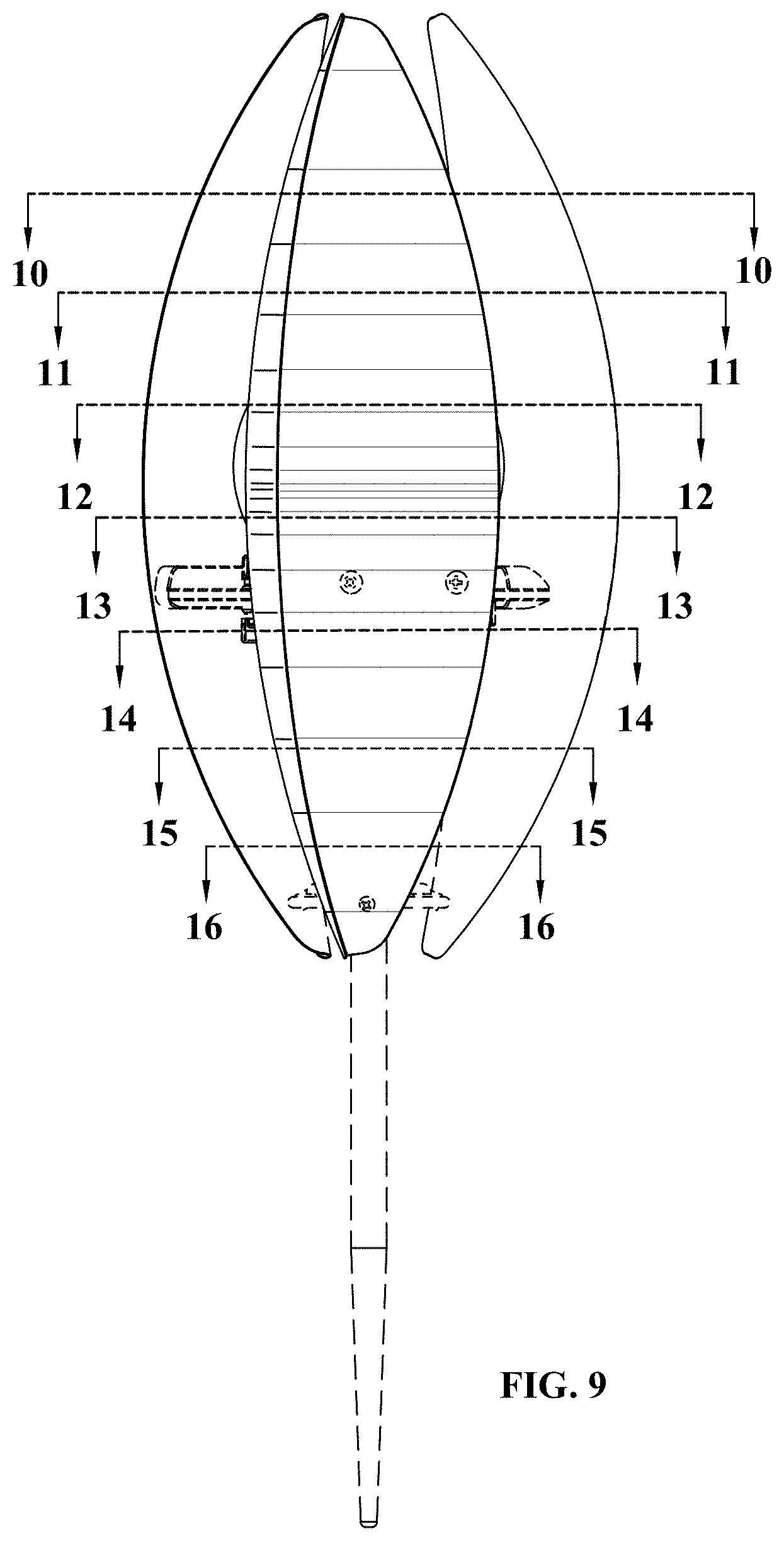
FIG. 9 is an enlarged front elevation view;
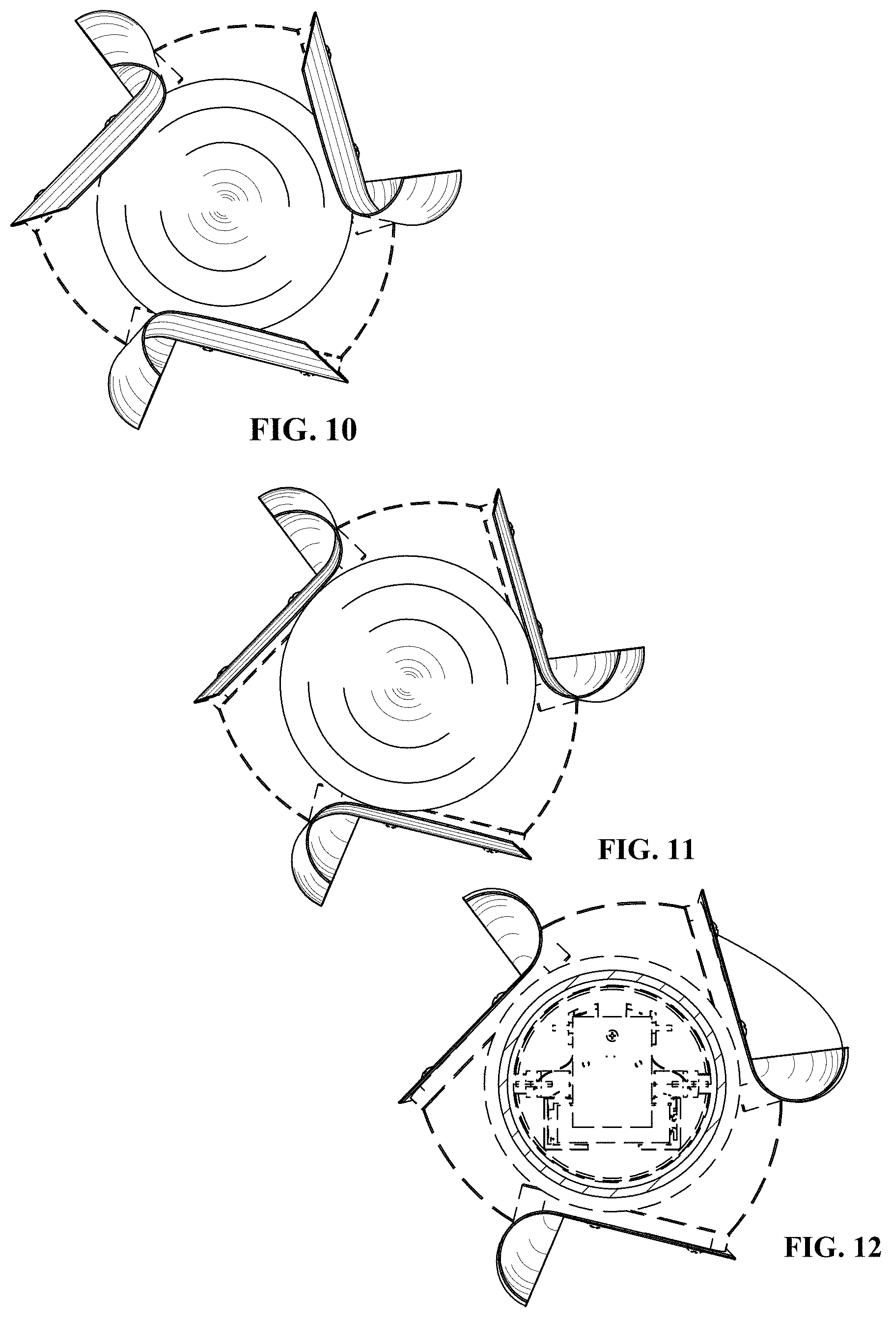
FIG. 10 is a cross section view taken along line 10-10 of FIG. 9;
FIG. 11 is a cross section view taken along line 11-11 of FIG. 9;
FIG. 12 is a cross section view taken along line 12-12 of FIG. 9;
FIG. 13 is a cross section view taken along line 13-13 of FIG. 9;
FIG. 14 is a cross section view taken along line 14-14 of FIG. 9;
FIG. 15 is a cross section view taken along line 15-15 of FIG. 9; and,
FIG. 16 is a cross section view taken along line 16-16 of FIG. 9.
In the drawings, the broken lines illustrate portions of the article which form no part of the claimed design.
* * * * *
References
D00000
D00001
D00002
D00003
D00004
D00005
D00006
D00007
XML
uspto.report is an independent third-party trademark research tool that is not affiliated, endorsed, or sponsored by the United States Patent and Trademark Office (USPTO) or any other governmental organization. The information provided by uspto.report is based on publicly available data at the time of writing and is intended for informational purposes only.
While we strive to provide accurate and up-to-date information, we do not guarantee the accuracy, completeness, reliability, or suitability of the information displayed on this site. The use of this site is at your own risk. Any reliance you place on such information is therefore strictly at your own risk.
All official trademark data, including owner information, should be verified by visiting the official USPTO website at www.uspto.gov. This site is not intended to replace professional legal advice and should not be used as a substitute for consulting with a legal professional who is knowledgeable about trademark law.