Monitor apparatus
Henderson March 16, 2
U.S. patent number D913,505 [Application Number D/685,766] was granted by the patent office on 2021-03-16 for monitor apparatus. This patent grant is currently assigned to EDAN INSTRUMENTS, INC.. The grantee listed for this patent is EDAN INSTRUMENTS, INC.. Invention is credited to Richard Henderson.

| United States Patent | D913,505 |
| Henderson | March 16, 2021 |
Monitor apparatus
Claims
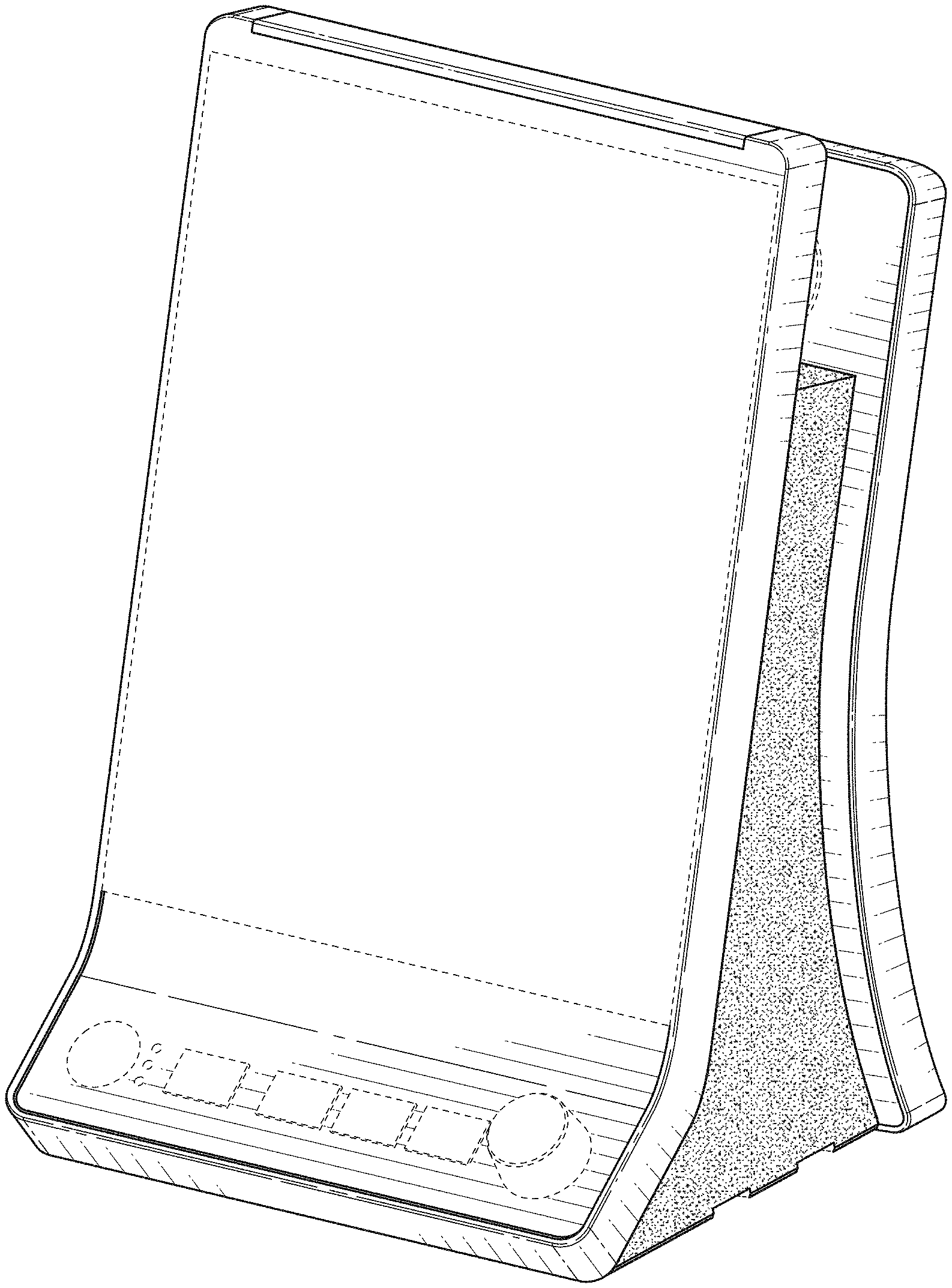
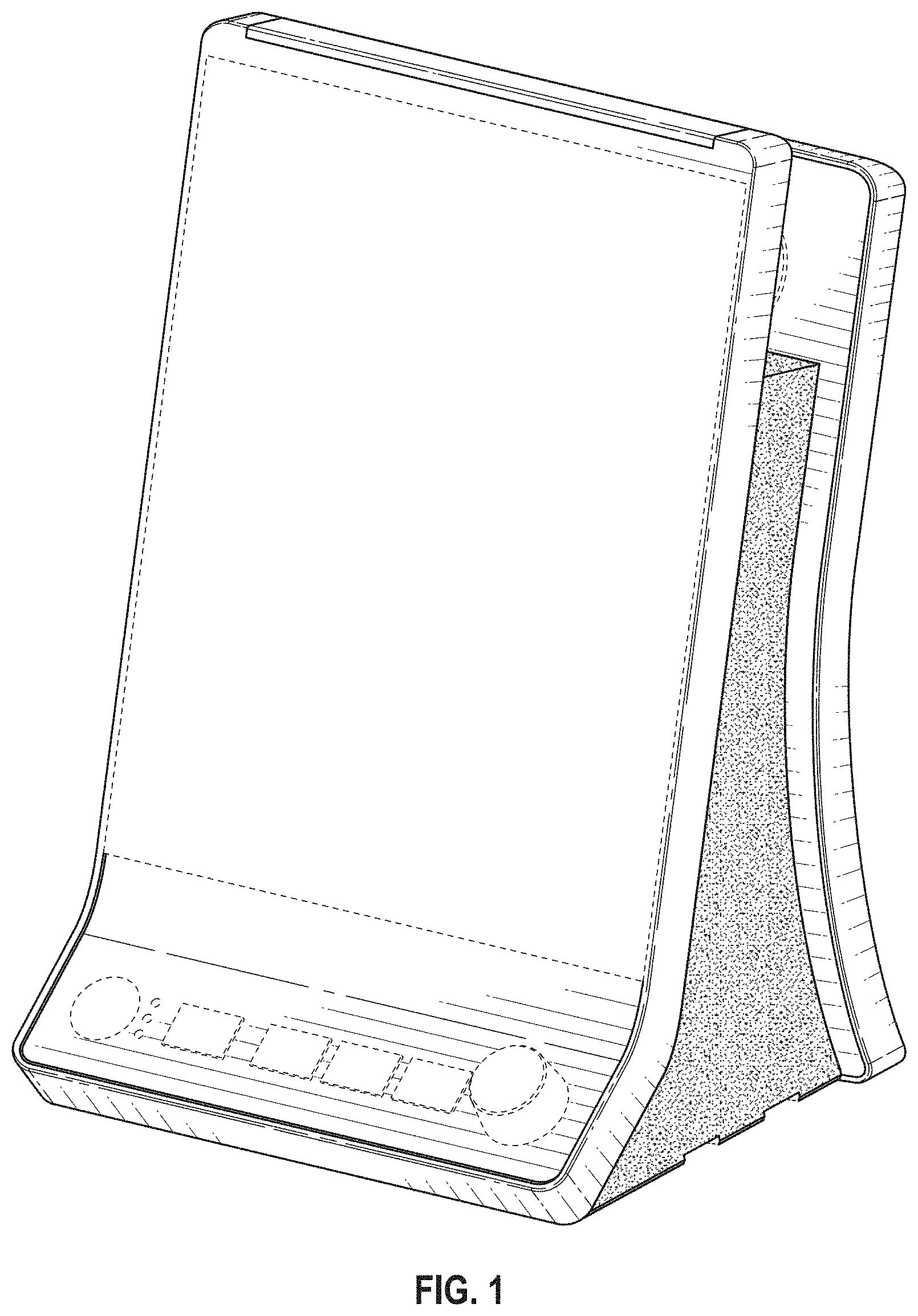
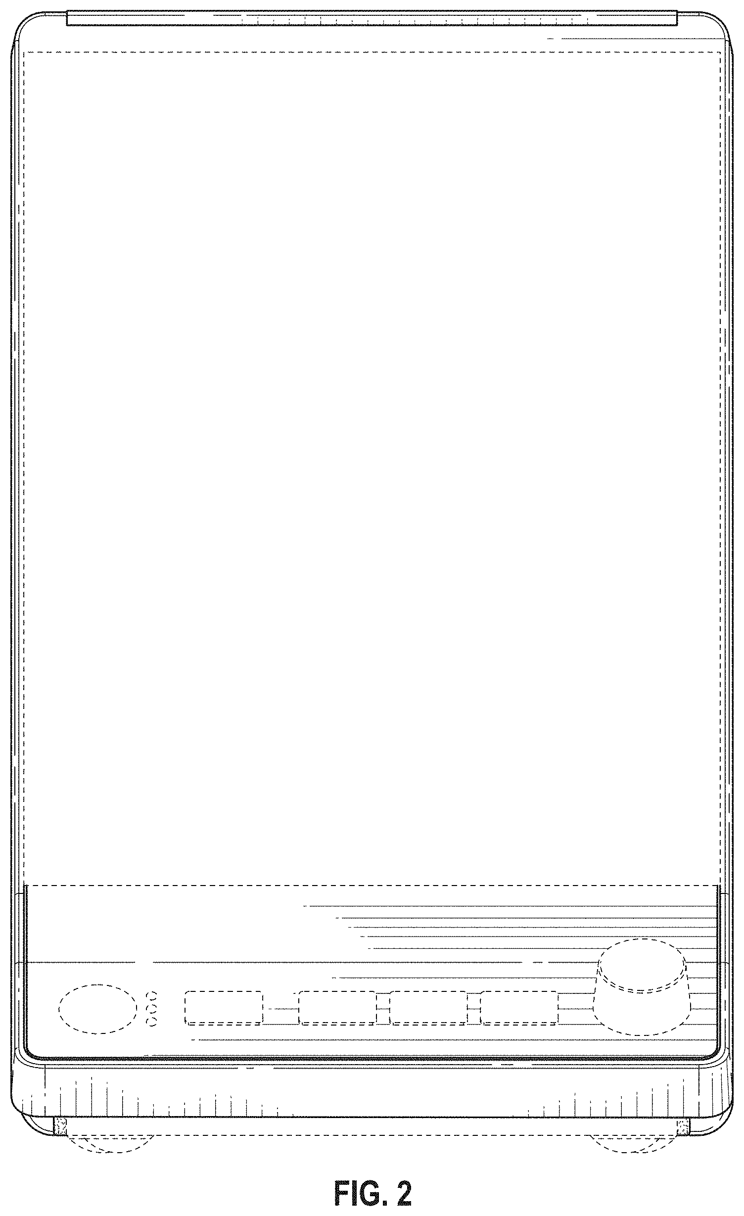
CLAIM I claim the ornamental design for a monitor apparatus, as shown and described.
| Inventors: | Henderson; Richard (Sunnyvale, CA) | ||||||||||
|---|---|---|---|---|---|---|---|---|---|---|---|
| Applicant: |
|
||||||||||
| Assignee: | EDAN INSTRUMENTS, INC.
(Shenzhen, CN) |
||||||||||
| Appl. No.: | D/685,766 | ||||||||||
| Filed: | March 29, 2019 |
Related U.S. Patent Documents
| Application Number | Filing Date | Patent Number | Issue Date | ||
|---|---|---|---|---|---|
| 29581810 | Oct 21, 2016 | D844791 | |||
| Current U.S. Class: | D24/186 |
| Current International Class: | 2401 |
| Field of Search: | ;D24/165-168,186,187,107,111,164,169,185,160 ;D10/70,75,98,81,104 ;D14/336,371,375,381,126 ;600/301,481,483-485,509,513,519,544 ;128/900 |
References Cited [Referenced By]
U.S. Patent Documents
| D398293 | September 1998 | Lindblom |
| D477084 | July 2003 | Menezes |
| D601258 | September 2009 | Bell |
| D616100 | May 2010 | Moscovita |
| D683034 | May 2013 | Shigeno |
| D697625 | January 2014 | Montgomery |
| D706239 | June 2014 | Chen |
| D711003 | August 2014 | Chen |
| D711004 | August 2014 | Chen |
| D765832 | September 2016 | Hochman |
| D788312 | May 2017 | Al-Ali |
| 9847002 | December 2017 | Kiani |
| 2013/0262730 | October 2013 | Al-Ali |
Other References
|
iM3 Vital Signs Monitor, posted at edan.com.cn, no posting date available, online, URL: http://www.edan.com.cn/html/EN/products/patientmonitoring/VSM/201712/2828- 62.html (Year: 2018). cited by examiner. |
Primary Examiner: Bekic; Lilyana
Assistant Examiner: Malley; Mary Shannon
Description
FIG. 1 is a top, front, right perspective view of the claimed design;
FIG. 2 is a front elevation view thereof;
FIG. 3 is a rear elevation view thereof;
FIG. 4 is a left elevation view thereof;
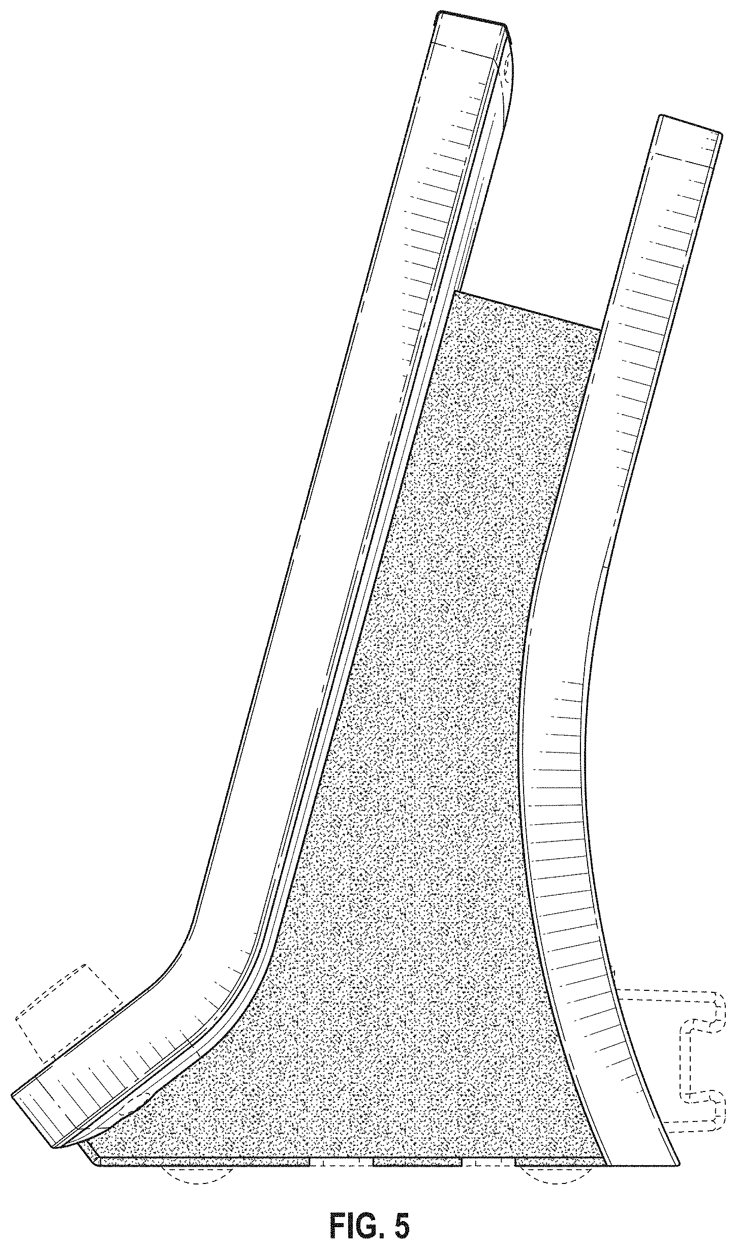
FIG. 5 is a right elevation view thereof;
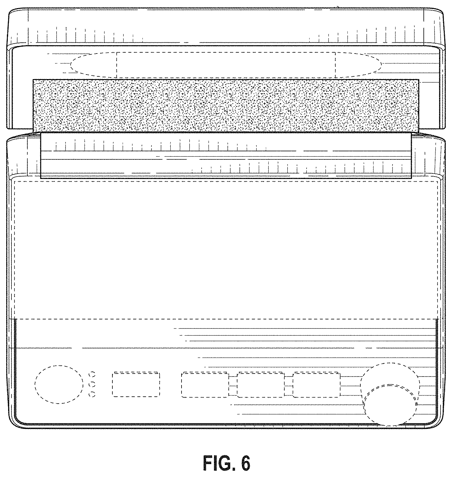
FIG. 6 is a top plan view thereof; and,
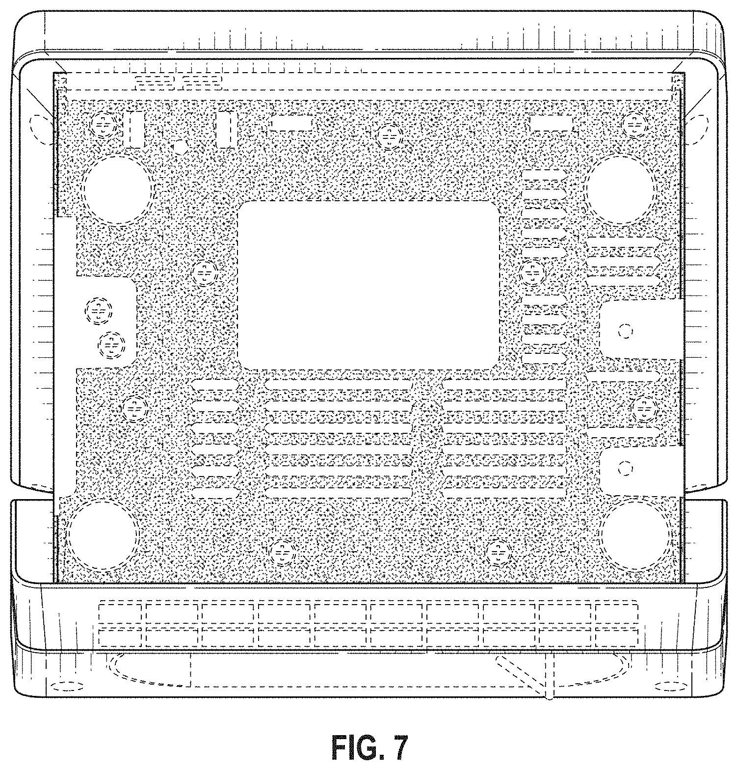
FIG. 7 is a bottom plan view thereof.
The broken lines in the drawings depict portions of the monitor apparatus that form no part of the claimed design. Portions shown in stipple shading as opposed to line shading show contrasting surfaces unlimited by colors.
* * * * *
References
D00000
D00001
D00002
D00003
D00004
D00005
D00006
D00007
XML
uspto.report is an independent third-party trademark research tool that is not affiliated, endorsed, or sponsored by the United States Patent and Trademark Office (USPTO) or any other governmental organization. The information provided by uspto.report is based on publicly available data at the time of writing and is intended for informational purposes only.
While we strive to provide accurate and up-to-date information, we do not guarantee the accuracy, completeness, reliability, or suitability of the information displayed on this site. The use of this site is at your own risk. Any reliance you place on such information is therefore strictly at your own risk.
All official trademark data, including owner information, should be verified by visiting the official USPTO website at www.uspto.gov. This site is not intended to replace professional legal advice and should not be used as a substitute for consulting with a legal professional who is knowledgeable about trademark law.