Wrench
Hsieh March 23, 2
U.S. patent number D913,763 [Application Number D/700,621] was granted by the patent office on 2021-03-23 for wrench. This patent grant is currently assigned to KABO TOOL COMPANY. The grantee listed for this patent is KABO TOOL COMPANY. Invention is credited to Chih-Ching Hsieh.


| United States Patent | D913,763 |
| Hsieh | March 23, 2021 |
Wrench
Claims
CLAIM The ornamental design for a wrench, as shown and described.
| Inventors: | Hsieh; Chih-Ching (Taichung, TW) | ||||||||||
|---|---|---|---|---|---|---|---|---|---|---|---|
| Applicant: |
|
||||||||||
| Assignee: | KABO TOOL COMPANY (Taichung,
TW) |
||||||||||
| Appl. No.: | D/700,621 | ||||||||||
| Filed: | August 3, 2019 |
Foreign Application Priority Data
| Apr 16, 2019 [TW] | 108302200 | |||
| Apr 16, 2019 [TW] | 108302201 | |||
| Current U.S. Class: | D8/21; D8/94; D8/24 |
| Current International Class: | 0805 |
| Field of Search: | ;D8/15-29,29.1,29.2,30-32,349,382-386,396-399,70,71,70.1,72-74,471,83,104-107,354,361,362,360,360.1,363-372,355-359 ;81/487,60,186,124,4,121.1,63.1,119,489,177.1,177.2,177.85,177.8,62,61 |
References Cited [Referenced By]
U.S. Patent Documents
| 37333 | January 1863 | Clough et al. |
| 232634 | September 1880 | Durgin |
| 355150 | December 1886 | Donoghue |
| D107311 | December 1937 | Dunn |
| 2646687 | July 1953 | De Wald |
| 4372356 | February 1983 | Conklin |
| D422192 | April 2000 | Cleveland |
| 6336383 | January 2002 | Hung |
| D527242 | August 2006 | Hsieh |
| D615466 | May 2010 | Domin |
| D641608 | July 2011 | Good |
| D700498 | March 2014 | Carter |
| D704521 | May 2014 | Su |
| 9021922 | May 2015 | Lai |
| D821167 | June 2018 | James |
| 2013/0228048 | September 2013 | Lai |
| 2014/0053689 | February 2014 | Lai |
| 302061011 | Jun 2012 | CN | |||
| 303205165 | Nov 2014 | CN | |||
| 305289917 | Aug 2018 | CN | |||
| 6051787 | Jan 2019 | GB | |||
| D1614696 | Dec 2017 | JP | |||
Other References
|
Williams, B-52EHLA 3/8-Inch Drive Long Enclosed Head Ratchet, Date first available Aug. 26, 2009, [online]retrieved Jul. 13, 2020, available from internet, www.amazon.com (Year: 2009). cited by examiner. |
Primary Examiner: Hill; Keli L
Assistant Examiner: Sahneh; Sara S
Attorney, Agent or Firm: Guice Patents PLLC
Description
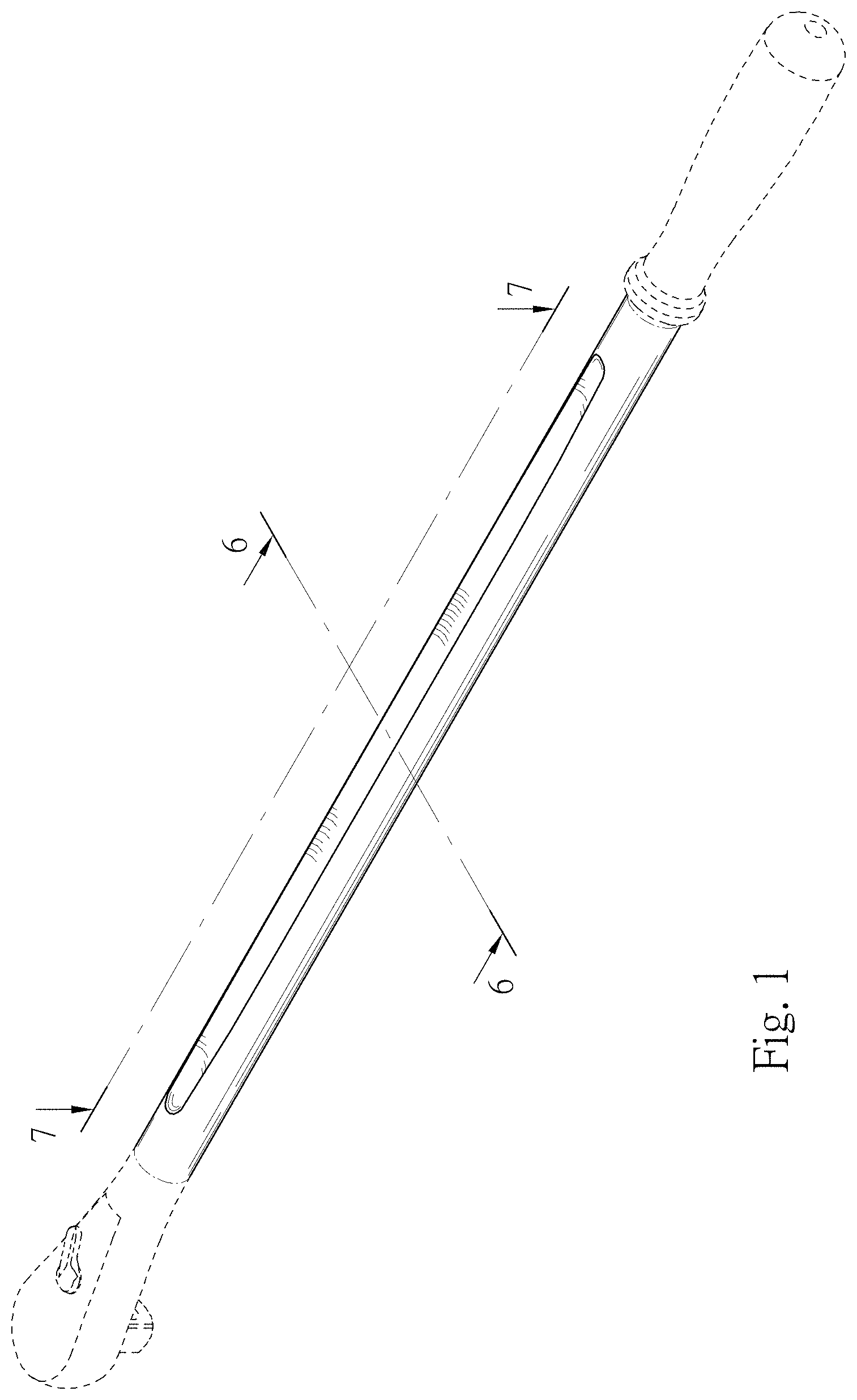
FIG. 1 is a perspective view of the wrench;
FIG. 2 is a front view of FIG. 1;
FIG. 3 is a rear view of FIG. 1;
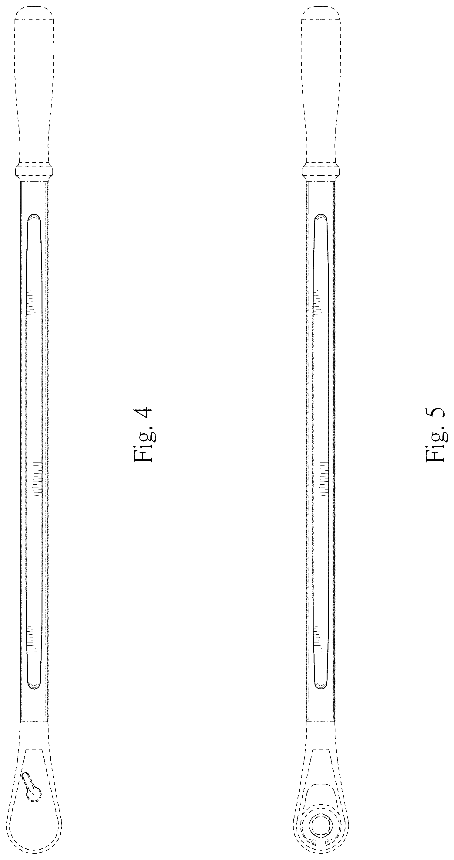
FIG. 4 is a top view of FIG. 1;
FIG. 5 is a bottom view of FIG. 1;
FIG. 6 is a sectional view taken along line 6-6 of FIG. 1; and,
FIG. 7 is a sectional view taken along line 7-7 of FIG. 1.
The broken lines shown are included for the purpose of illustrating portions of the Wrench that form no part of the claimed design.
* * * * *
References
D00000
D00001
D00002
D00003
D00004
D00005
XML
uspto.report is an independent third-party trademark research tool that is not affiliated, endorsed, or sponsored by the United States Patent and Trademark Office (USPTO) or any other governmental organization. The information provided by uspto.report is based on publicly available data at the time of writing and is intended for informational purposes only.
While we strive to provide accurate and up-to-date information, we do not guarantee the accuracy, completeness, reliability, or suitability of the information displayed on this site. The use of this site is at your own risk. Any reliance you place on such information is therefore strictly at your own risk.
All official trademark data, including owner information, should be verified by visiting the official USPTO website at www.uspto.gov. This site is not intended to replace professional legal advice and should not be used as a substitute for consulting with a legal professional who is knowledgeable about trademark law.