Steering wheel for game consoles
Conrad February 23, 2
U.S. patent number D911,447 [Application Number D/655,489] was granted by the patent office on 2021-02-23 for steering wheel for game consoles. This patent grant is currently assigned to ENDOR AG. The grantee listed for this patent is ENDOR AG. Invention is credited to Bernhard Conrad.


View All Diagrams
| United States Patent | D911,447 |
| Conrad | February 23, 2021 |
Steering wheel for game consoles
Claims
CLAIM The ornamental design for a steering wheel for game consoles, as shown and described.
| Inventors: | Conrad; Bernhard (Buch am Erlbach, DE) | ||||||||||
|---|---|---|---|---|---|---|---|---|---|---|---|
| Applicant: |
|
||||||||||
| Assignee: | ENDOR AG (Landshut,
DE) |
||||||||||
| Appl. No.: | D/655,489 | ||||||||||
| Filed: | July 3, 2018 |
| Current U.S. Class: | D21/333; D12/175 |
| Current International Class: | 2102 |
| Field of Search: | ;D12/175-177 ;D14/401,414 ;D21/333,385,477,566 |
References Cited [Referenced By]
U.S. Patent Documents
| D533142 | December 2006 | Chen |
| D548653 | August 2007 | Costa |
| D573198 | July 2008 | Bramfitt |
| D592114 | May 2009 | Tombazis |
| D627831 | November 2010 | Tombazis |
| D631922 | February 2011 | Kang |
| D633853 | March 2011 | Aruga |
| D638017 | May 2011 | Ortiz |
| D657923 | April 2012 | Dammkoehler |
| D708675 | July 2014 | Delrue |
| D769781 | October 2016 | Allison |
| D776023 | January 2017 | Allison |
| D787994 | May 2017 | Carbone |
| D813123 | March 2018 | Allison |
| D867237 | November 2019 | Resta |
| 2006/0258452 | November 2006 | Hsu |
Other References
|
Fanatec Opens Limited Pre-Orders for New CSL Elite McLaren GT3 Wheel: Published Nov. 27, 2017 [online], site visited Mar. 19, 2020 . Available from Internet URL:https://www.gtplanet.net/fanatec-csl-elite-mclaren-gt3/ (Year: 2017). cited by examiner. |
Primary Examiner: Stout; Michael C
Assistant Examiner: Davis; Melvin L
Attorney, Agent or Firm: The Culbertson Group, P.C.
Description
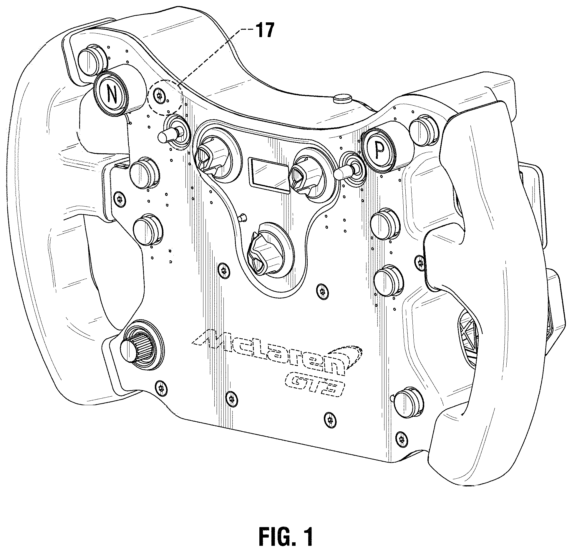
FIG. 1 is a right perspective view from the front and above a steering wheel showing the new design.
FIG. 2 is a right perspective view from the rear and above the steering wheel shown in FIG. 1
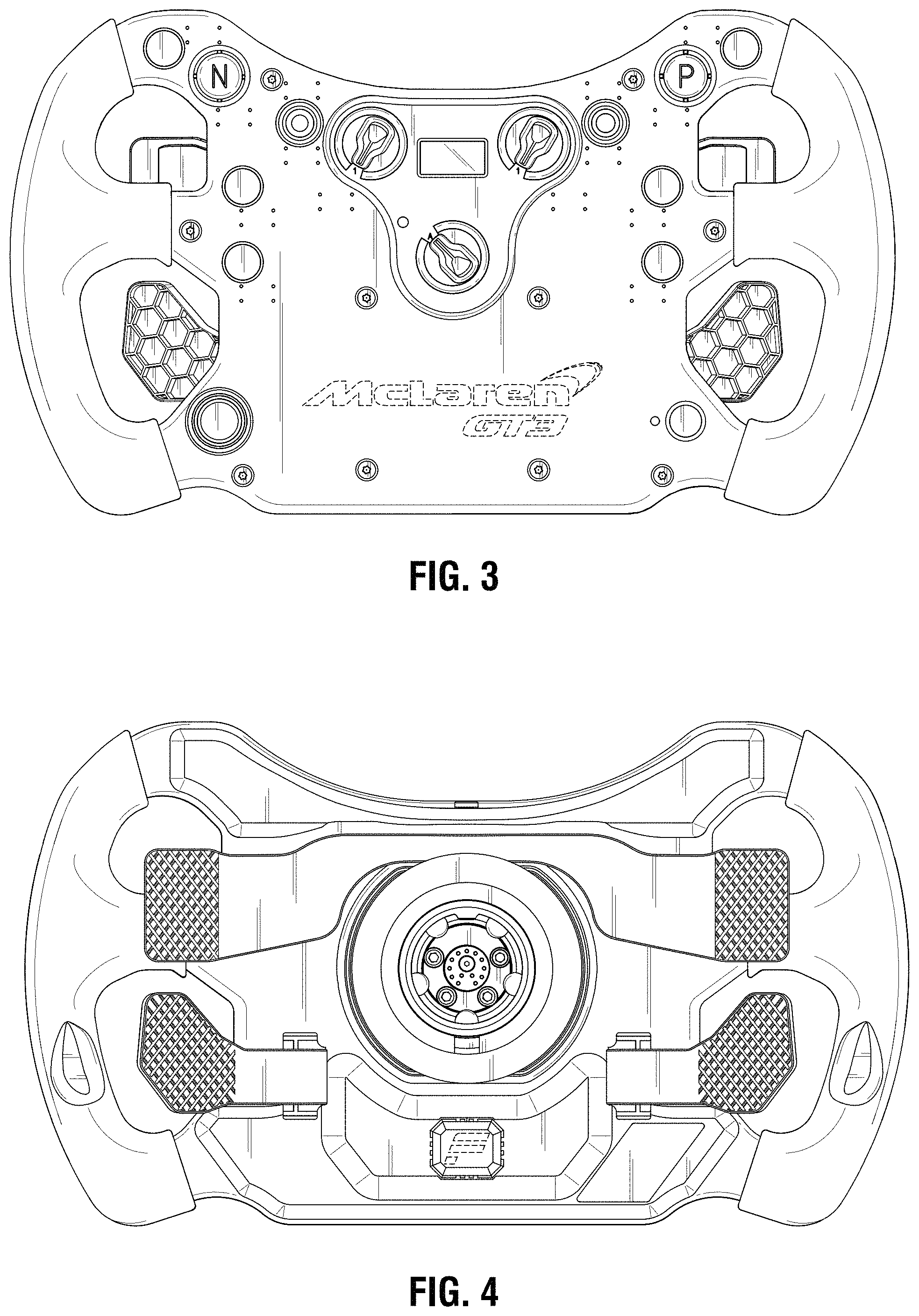
FIG. 3 is a front view of the steering wheel shown in FIG. 1.
FIG. 4 is a rear view of the steering wheel shown in FIG. 1.
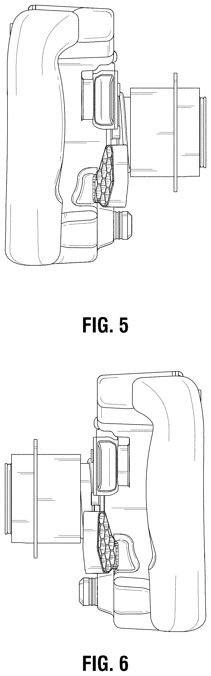
FIG. 5 is a right side view of the steering wheel shown in FIG. 1.
FIG. 6 is a left side view of the steering wheel shown in FIG. 1.
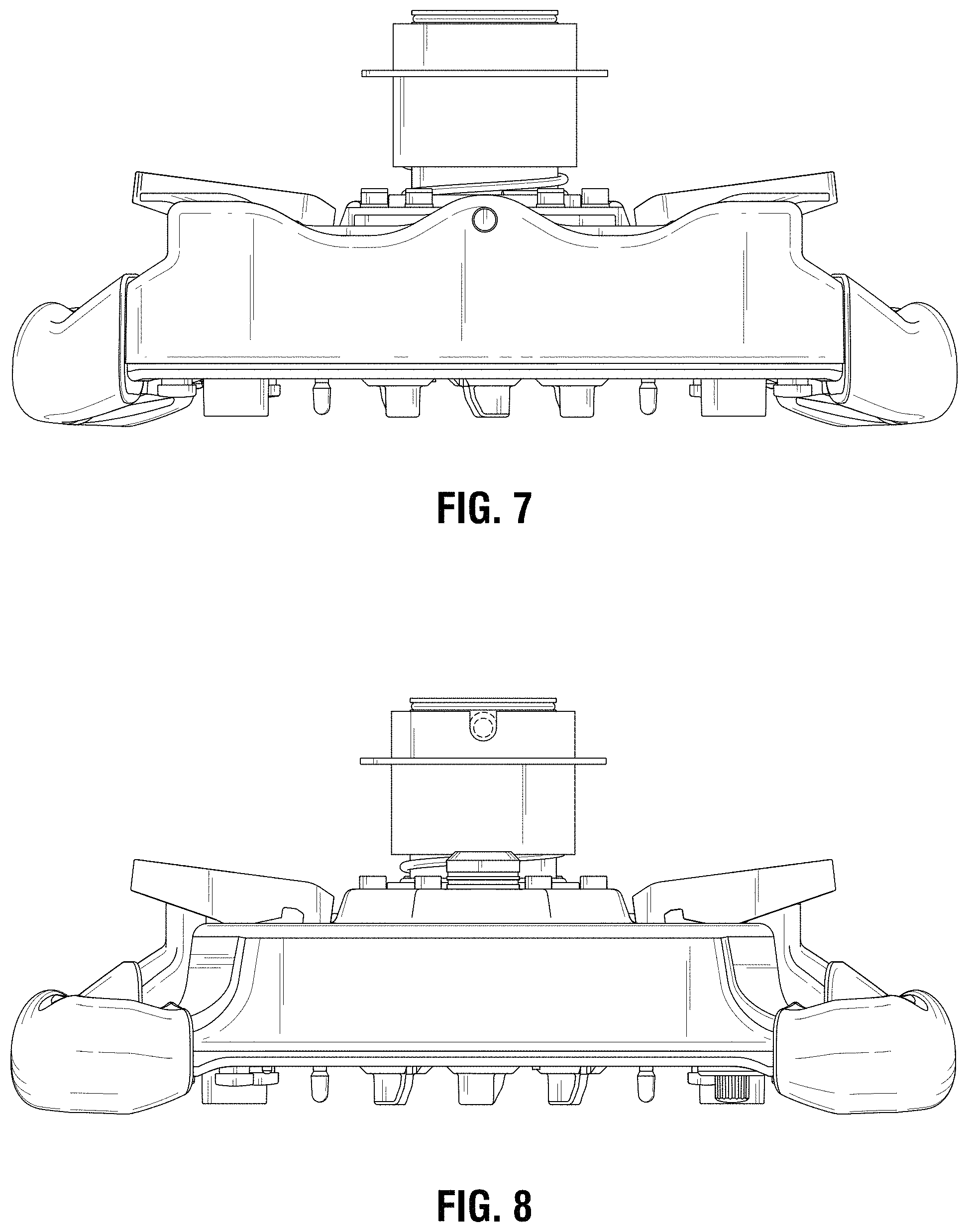
FIG. 7 is a top view of the steering wheel shown in FIG. 1
FIG. 8 is a bottom view of the steering wheel shown in FIG. 1.
FIG. 9 is a right perspective view from the front and above an alternate embodiment of a steering wheel showing the new design.
FIG. 10 is a right perspective view from the rear and above the steering wheel shown in FIG. 9
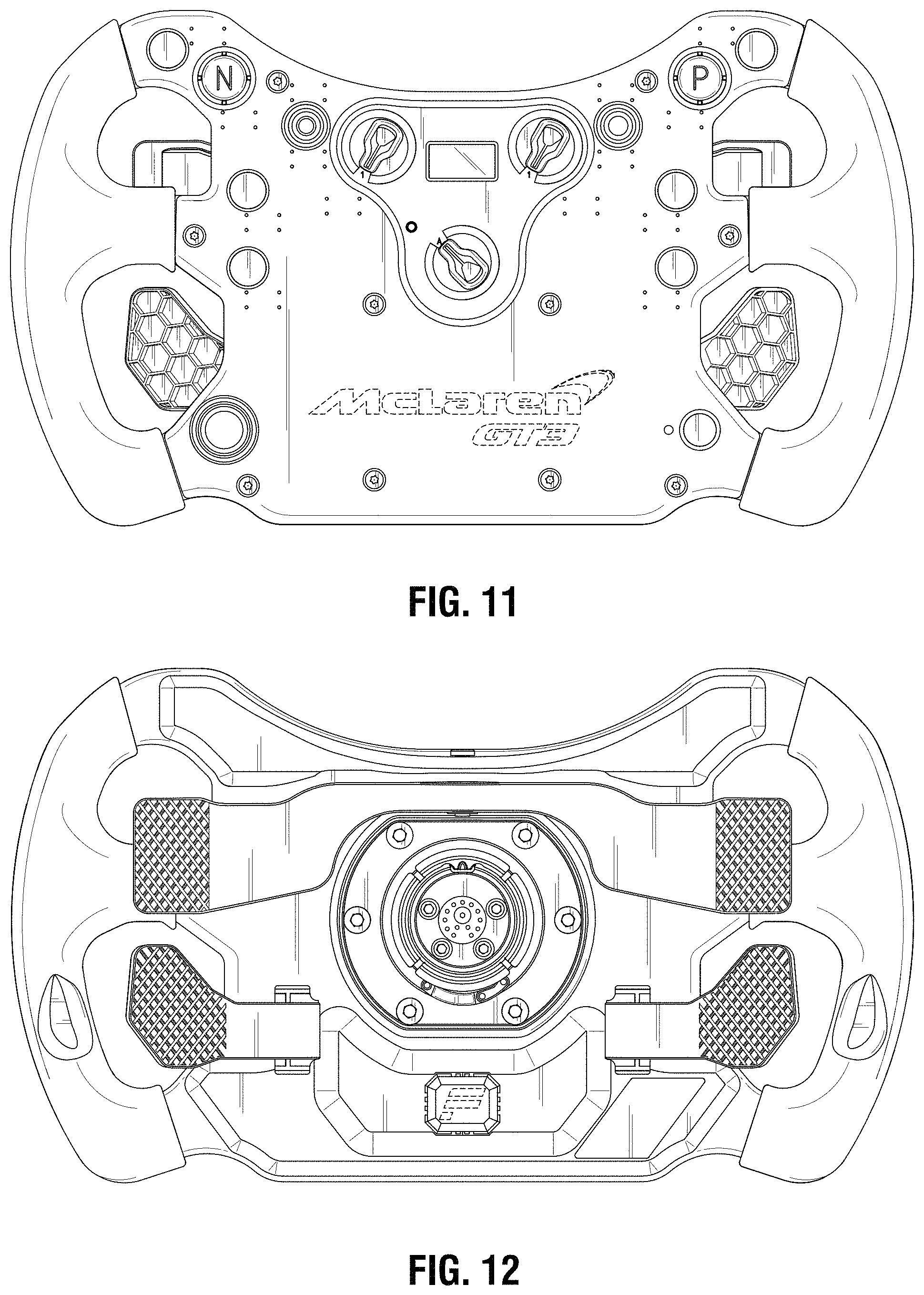
FIG. 11 is a front view of the steering wheel shown in FIG. 9.
FIG. 12 is a rear view of the steering wheel shown in FIG. 9.
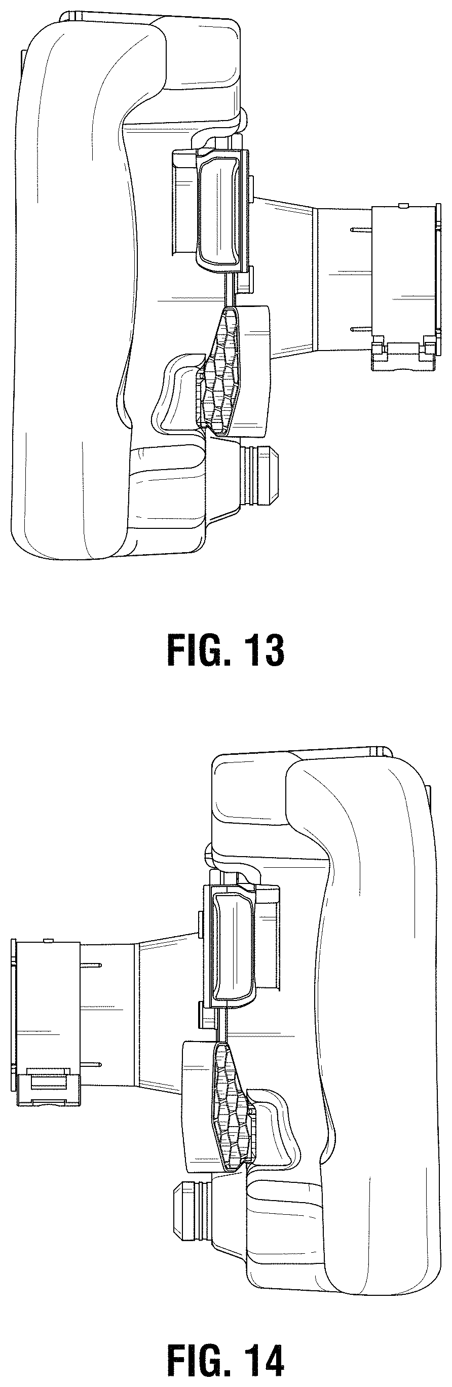
FIG. 13 is a right side view of the steering wheel shown in FIG. 9.
FIG. 14 is a left side view of the steering wheel shown in FIG. 9.
FIG. 15 is a top view of the steering wheel shown in FIG. 9.
FIG. 16 is a bottom view of the steering wheel shown in FIG. 9.
FIG. 17 is an enlarged perspective view of the steering wheel portion called out in FIG. 1; and,
FIG. 18 is an enlarged perspective view of the steering wheel portion called out in FIG. 2.
The broken lines shown in the drawings depict portions of the steering wheel that form no part of the claimed design.
* * * * *
References
D00000
D00001
D00002
D00003
D00004
D00005
D00006
D00007
D00008
D00009
D00010
D00011
XML
uspto.report is an independent third-party trademark research tool that is not affiliated, endorsed, or sponsored by the United States Patent and Trademark Office (USPTO) or any other governmental organization. The information provided by uspto.report is based on publicly available data at the time of writing and is intended for informational purposes only.
While we strive to provide accurate and up-to-date information, we do not guarantee the accuracy, completeness, reliability, or suitability of the information displayed on this site. The use of this site is at your own risk. Any reliance you place on such information is therefore strictly at your own risk.
All official trademark data, including owner information, should be verified by visiting the official USPTO website at www.uspto.gov. This site is not intended to replace professional legal advice and should not be used as a substitute for consulting with a legal professional who is knowledgeable about trademark law.