Three-piece beverage tray carrier set
Cabrera , et al. February 16, 2
U.S. patent number D910,380 [Application Number D/693,008] was granted by the patent office on 2021-02-16 for three-piece beverage tray carrier set. The grantee listed for this patent is Mario A. Cabrera, Rodolfo R. Cabrera. Invention is credited to Mario A. Cabrera, Rodolfo R. Cabrera.


| United States Patent | D910,380 |
| Cabrera , et al. | February 16, 2021 |
Three-piece beverage tray carrier set
Claims
CLAIM I claim the ornamental design for a three-piece beverage tray carrier set, as shown and described.
| Inventors: | Cabrera; Mario A. (Banning, CA), Cabrera; Rodolfo R. (Lake Havasu City, AZ) | ||||||||||
|---|---|---|---|---|---|---|---|---|---|---|---|
| Applicant: |
|
||||||||||
| Appl. No.: | D/693,008 | ||||||||||
| Filed: | May 30, 2019 |
| Current U.S. Class: | D7/552.1 |
| Current International Class: | 0701 |
| Field of Search: | ;D7/543,546,550.1,552.1,552.2,553.2,553.4,554.3,555 |
References Cited [Referenced By]
U.S. Patent Documents
| D76744 | October 1928 | Forman |
| D238845 | February 1976 | Logue |
| 4502460 | March 1985 | Kelz |
| D366394 | January 1996 | Kypreos |
| D688915 | September 2013 | Green |
| D724072 | March 2015 | Jiang |
| D828106 | September 2018 | Mashburn |
| D855038 | July 2019 | Hu |
| D879075 | March 2020 | Xu |
| 2005/0103957 | May 2005 | Chang |
Attorney, Agent or Firm: Clarke; Richard D.
Description
FIG. 1 is a top perspective view of a three-piece beverage tray carrier set;
FIG. 2 is a top perspective view of the three-piece beverage tray carrier set shown with one carrier and screw handle;
FIG. 3 is a top perspective view thereof and environment;
FIG. 4 is a right side elevation view thereof shown without the screw handle;
FIG. 5 is a top plan view of FIG. 4;
FIG. 6 is a left side view of FIG. 4;
FIG. 7 is a cross sectional view taken along 7-7 in FIG. 5 of FIG. 4;
FIG. 8 is a bottom view thereof;
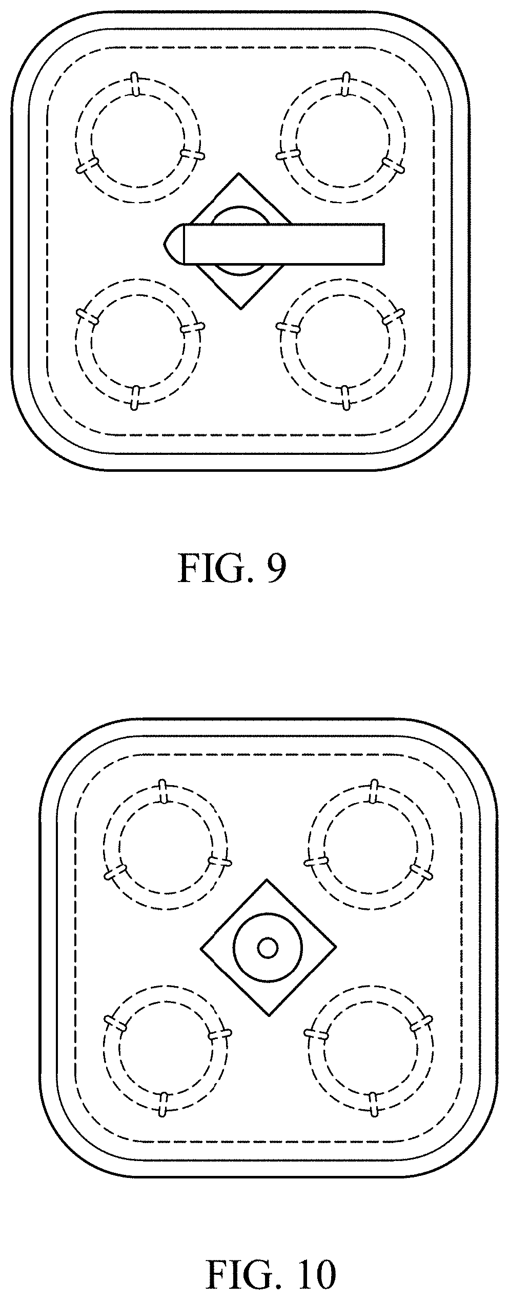
FIG. 9 is a top plan view of FIG. 3;
FIG. 10 is a top plan view of FIG. 3 without screw handle;
FIG. 11 is a front view of a coupling handle;
FIG. 12 is a side elevation view of FIG. 11;
FIG. 13 is a side elevation view of a screw handle;
FIG. 14 is a front view thereof; and,
FIG. 15 is a top perspective view of FIG. 2 shown with the screw handle in a storage position.
The broken lines in FIGS. 2, 8 and 9 of the drawings show unclaimed environment only and form no part of the claimed design.
* * * * *
D00000
D00001
D00002
D00003
D00004
D00005
D00006
XML
uspto.report is an independent third-party trademark research tool that is not affiliated, endorsed, or sponsored by the United States Patent and Trademark Office (USPTO) or any other governmental organization. The information provided by uspto.report is based on publicly available data at the time of writing and is intended for informational purposes only.
While we strive to provide accurate and up-to-date information, we do not guarantee the accuracy, completeness, reliability, or suitability of the information displayed on this site. The use of this site is at your own risk. Any reliance you place on such information is therefore strictly at your own risk.
All official trademark data, including owner information, should be verified by visiting the official USPTO website at www.uspto.gov. This site is not intended to replace professional legal advice and should not be used as a substitute for consulting with a legal professional who is knowledgeable about trademark law.