Fluid pressure cylinder
Nemoto , et al. February 2, 2
U.S. patent number D909,419 [Application Number D/706,492] was granted by the patent office on 2021-02-02 for fluid pressure cylinder. This patent grant is currently assigned to SMC CORPORATION. The grantee listed for this patent is SMC CORPORATION. Invention is credited to Sho Aso, Masahiko Kawakami, Yuu Mizutani, Shinichiro Nemoto, Shuichi Shibuya.


View All Diagrams
| United States Patent | D909,419 |
| Nemoto , et al. | February 2, 2021 |
Fluid pressure cylinder
Claims
CLAIM The ornamental design for a fluid pressure cylinder, as shown and described.
| Inventors: | Nemoto; Shinichiro (Tsukubamirai, JP), Mizutani; Yuu (Tsukubamirai, JP), Kawakami; Masahiko (Tsukubamirai, JP), Aso; Sho (Tsukubamirai, JP), Shibuya; Shuichi (Tsukubamirai, JP) | ||||||||||
|---|---|---|---|---|---|---|---|---|---|---|---|
| Applicant: |
|
||||||||||
| Assignee: | SMC CORPORATION (Tokyo,
JP) |
||||||||||
| Appl. No.: | D/706,492 | ||||||||||
| Filed: | September 20, 2019 |
Foreign Application Priority Data
| Mar 29, 2019 [CN] | 2019 3 0137122 | |||
| Current U.S. Class: | D15/7 |
| Current International Class: | 1502 |
| Field of Search: | ;D15/7,9,143,148,149,199 ;D10/85 ;D23/225,233,235 |
References Cited [Referenced By]
U.S. Patent Documents
| D295753 | May 1988 | LaBair |
| 4825746 | May 1989 | Herner |
| D303393 | September 1989 | Stoll |
| 5163351 | November 1992 | Dominka |
| D333474 | February 1993 | Aizawa |
| D370683 | June 1996 | Stahlman |
| 5555789 | September 1996 | Rosengren |
| D417457 | December 1999 | Asahara |
| D420683 | February 2000 | Suzuki |
| D428617 | July 2000 | Hariwara |
| 6089111 | July 2000 | Machijima |
| 6152015 | November 2000 | Migliori |
| D445704 | July 2001 | Suzuki |
| D480405 | October 2003 | Kleffmann |
| D499348 | December 2004 | Matsumoto |
| D500258 | December 2004 | Kita |
| D500259 | December 2004 | Kita |
| D572282 | July 2008 | Yaegashi |
| D575175 | August 2008 | Suzuki |
| D584324 | January 2009 | Yaegashi |
| D600534 | September 2009 | Tokumoto |
| D669097 | October 2012 | Hariwara |
| D669098 | October 2012 | Hariwara |
| D682901 | May 2013 | Peschel |
| D685014 | June 2013 | Mangold |
| D685403 | July 2013 | Mangold |
| D687516 | August 2013 | Asaba |
| D689524 | September 2013 | Peschel |
| D689525 | September 2013 | Peschel |
| D699759 | February 2014 | Peschel |
| D699760 | February 2014 | Peschel |
| D699761 | February 2014 | Peschel |
| D757120 | May 2016 | Kudo |
| D760805 | July 2016 | Monden |
| D770595 | November 2016 | Suzuki |
| D772302 | November 2016 | Kudo |
| D780228 | February 2017 | Kudo |
| D780229 | February 2017 | Kudo |
| D794164 | August 2017 | Suzuki |
| D805559 | December 2017 | Kudo |
| D805560 | December 2017 | Kudo |
| D819700 | June 2018 | Kudo |
| D820321 | June 2018 | Kudo |
| D825616 | August 2018 | Monden |
| D826285 | August 2018 | Yaegashi |
| D871457 | December 2019 | Ikari |
| D888769 | June 2020 | Mizutani |
| D888770 | June 2020 | Mizutani |
| D888771 | June 2020 | Mizutani |
| D888772 | June 2020 | Sato |
| D888773 | June 2020 | Sato |
| D888774 | June 2020 | Asahara |
| D888775 | June 2020 | Sato |
| D890213 | July 2020 | Sato |
| D890214 | July 2020 | Sato |
| D890215 | July 2020 | Sato |
| D892980 | August 2020 | Sato |
| D894965 | September 2020 | Nagai |
| D899466 | October 2020 | Nemoto |
| 2011/0126703 | June 2011 | Terasaki |
| 2017/0298931 | October 2017 | Kudo |
| 2020/0109782 | April 2020 | Odaka |
| 2020/0300276 | September 2020 | Tamura |
| 304695093 | Jun 2018 | CN | |||
| 846878-1 | Sep 1992 | JP | |||
| 846878 | Sep 1992 | JP | |||
| 110350 | Jun 2001 | JP | |||
| 1615185 | Oct 2018 | JP | |||
Other References
|
SMC, Compact Air Cylinder--Standard Type, 2 in Bore, (first available Jul. 19, 2019), Amazon.com, URL:<https://www.amazon.com/Compact-Air-Cylinder-Standard-Type/dp/B07V- JX3FJS> (Year: 2019). cited by examiner . SMC, C(D)QSX, Compact Cylinder, Double Acting, Single Rod, Low Speed, (site visited Nov. 14, 2020), SCM USA website, URL:<https://www.smcusa.com/products/C(D)QSX-Compact-Cylinder-Double-A- cting-Single-Rod-Low-Speed-53749> (Year: 2020). cited by examiner. |
Primary Examiner: Lane; Sheryl
Assistant Examiner: Philipps; Mark T
Attorney, Agent or Firm: Birch, Stewart, Kolasch & Birch, LLP
Description
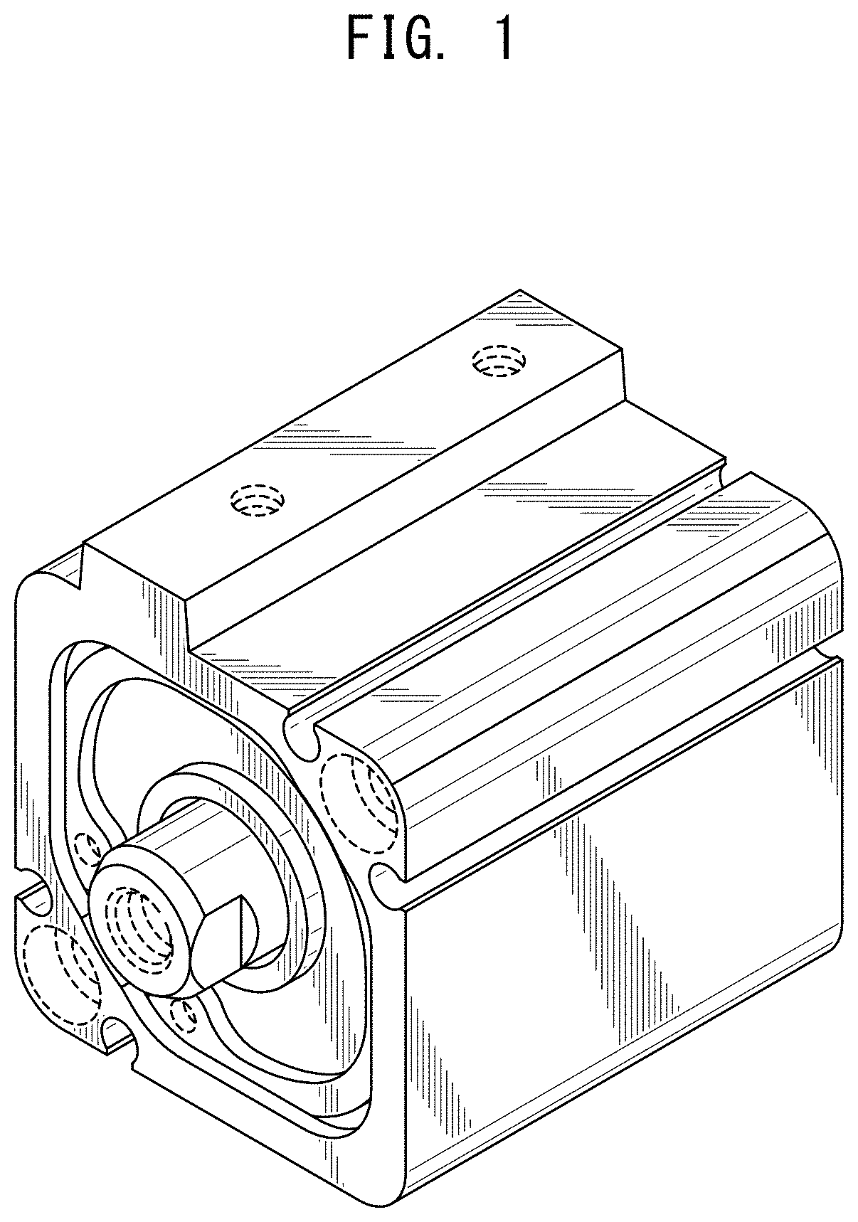
FIG. 1 is a front, top and left side perspective view of a fluid pressure cylinder showing a first embodiment of our new design;
FIG. 2 is a rear, bottom and right side perspective view thereof;
FIG. 3 is a front view thereof;
FIG. 4 is a rear view thereof;
FIG. 5 is a top plan view thereof;
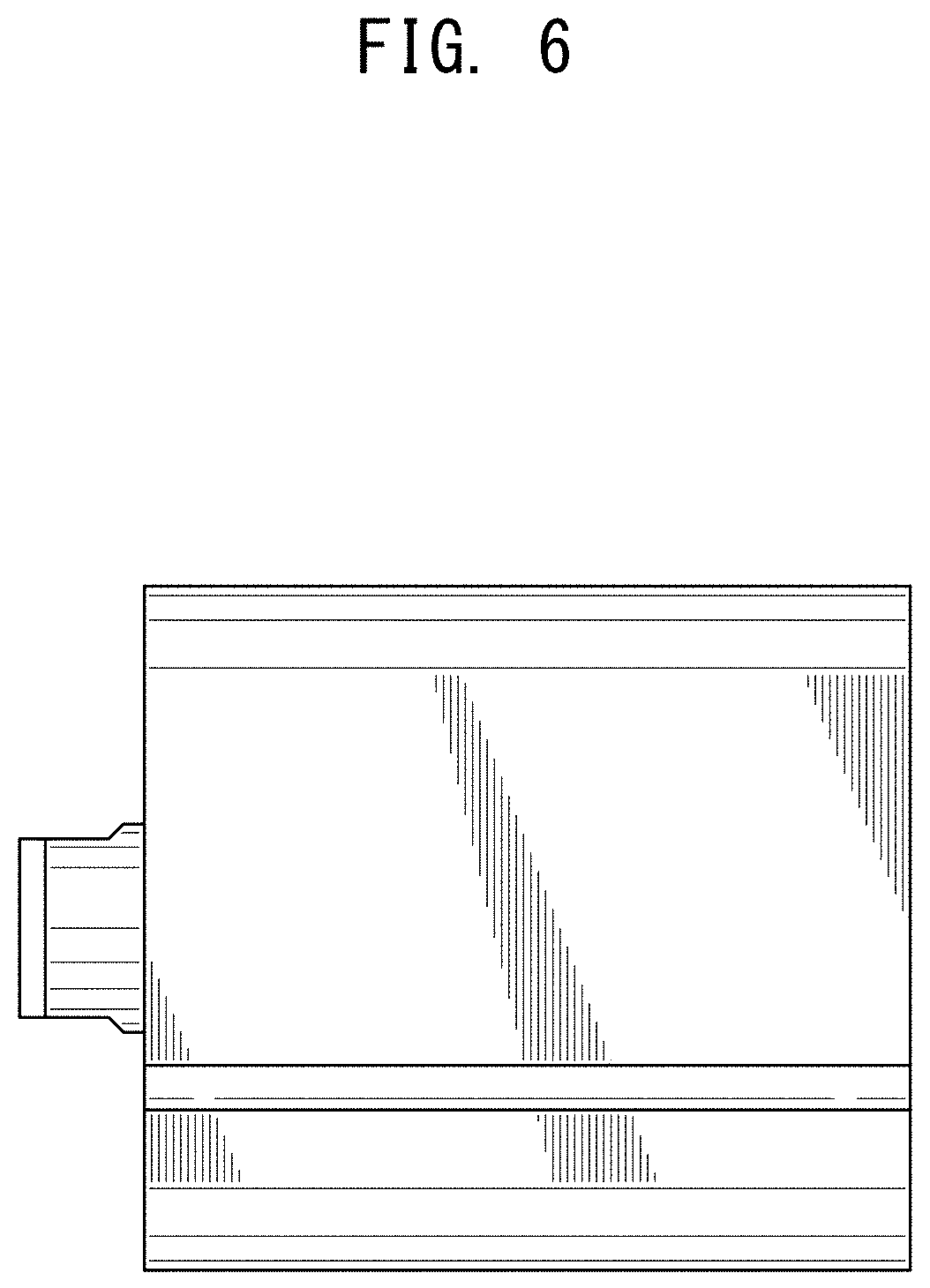
FIG. 6 is a bottom plan view thereof;
FIG. 7 is a left side view thereof;
FIG. 8 is a right side view thereof;
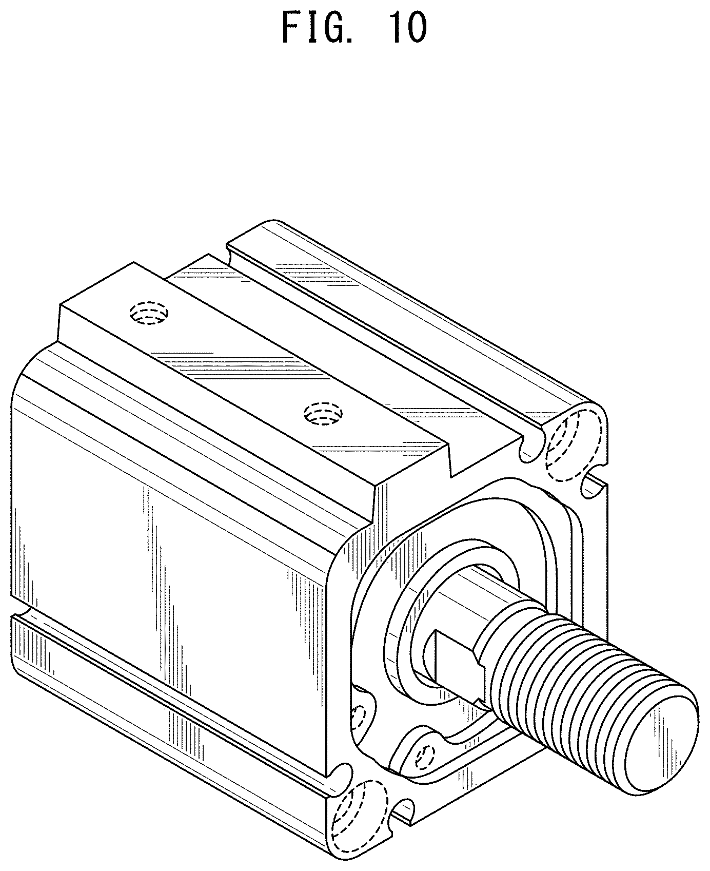
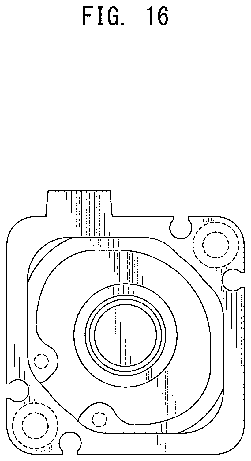
FIG. 9 is a front, top and left side perspective view of a fluid pressure cylinder showing a second embodiment of our new design;
FIG. 10 is a rear, top and left side perspective view of FIG. 9;
FIG. 11 is a rear, bottom and right side perspective view of FIG. 9;
FIG. 12 is a front view of FIG. 9;
FIG. 13 is a rear view of FIG. 9;
FIG. 14 is a top plan view of FIG. 9;
FIG. 15 is a bottom plan view of FIG. 9;
FIG. 16 is a left side view of FIG. 9;
FIG. 17 is a right side view of FIG. 9;
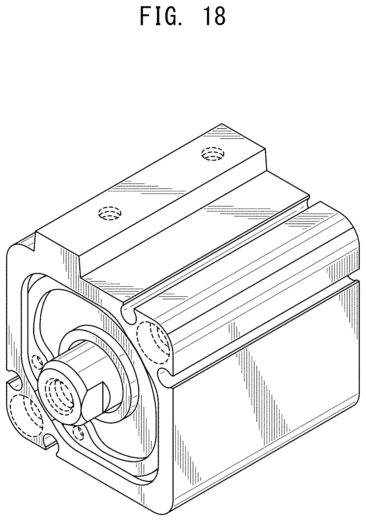
FIG. 18 is a front, top and left side perspective view of a fluid pressure cylinder showing a third embodiment of our new design;
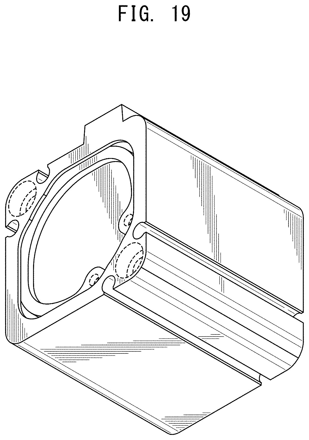
FIG. 19 is a rear, bottom and right side perspective view of FIG. 18;
FIG. 20 is a front view of FIG. 18;
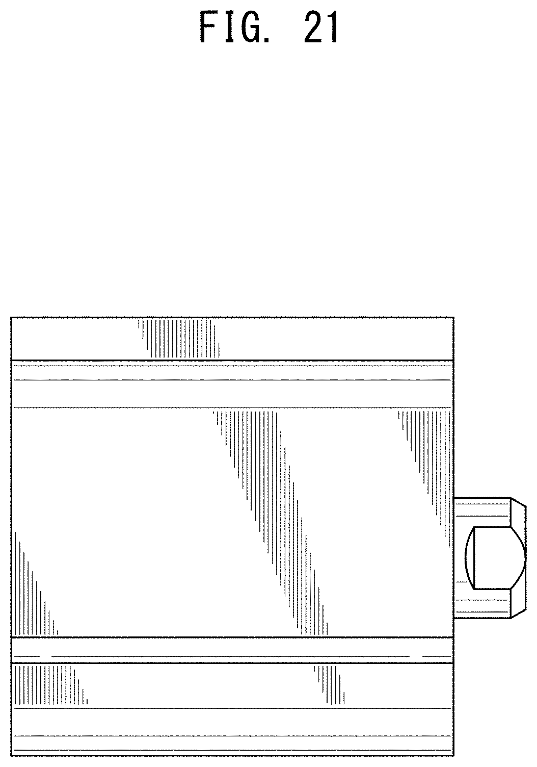
FIG. 21 is a rear view of FIG. 18;
FIG. 22 is a top plan view of FIG. 18;
FIG. 23 is a bottom plan view of FIG. 18;
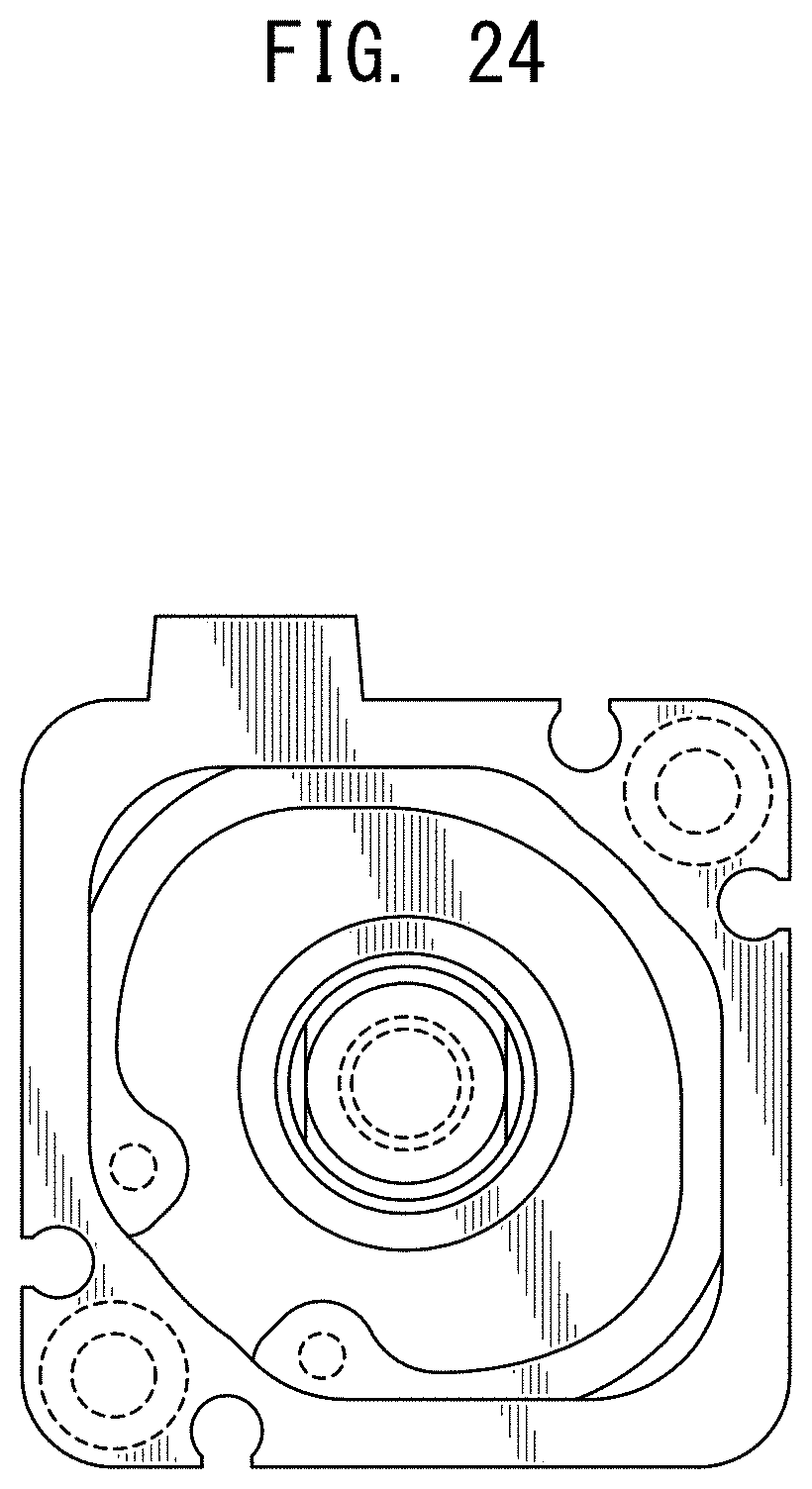
FIG. 24 is a left side view of FIG. 18;
FIG. 25 is a right side view of FIG. 18;
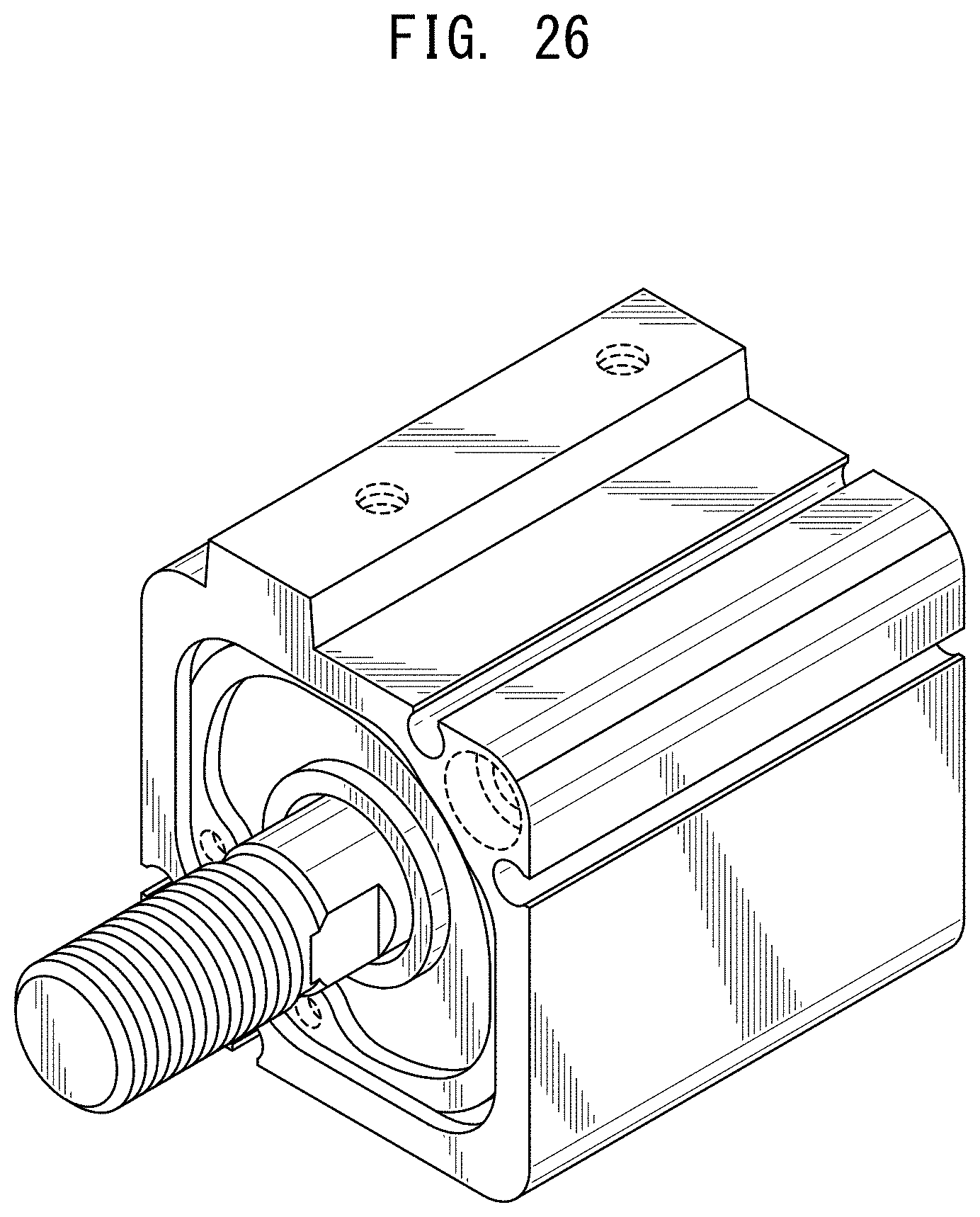
FIG. 26 is a front, top and left side perspective view of a fluid pressure cylinder showing a fourth embodiment of our new design;
FIG. 27 is a rear, top and left side perspective view of FIG. 26;
FIG. 28 is a rear, bottom and right side perspective view of FIG. 26;
FIG. 29 is a front view of FIG. 26;
FIG. 30 is a rear view of FIG. 26;
FIG. 31 is a top plan view of FIG. 26;
FIG. 32 is a bottom plan view of FIG. 26;
FIG. 33 is a left side view of FIG. 26; and,
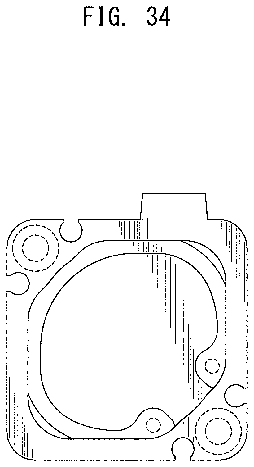
FIG. 34 is a right side view of FIG. 26.
The broken lines depict portions of the fluid pressure cylinder that form no part of the claimed design.
* * * * *
References
D00000
D00001
D00002
D00003
D00004
D00005
D00006
D00007
D00008
D00009
D00010
D00011
D00012

D00013

D00014

D00015

D00016
D00017

D00018
D00019
D00020

D00021
D00022

D00023

D00024
D00025

D00026
D00027

D00028

D00029

D00030

D00031

D00032

D00033

D00034
XML
uspto.report is an independent third-party trademark research tool that is not affiliated, endorsed, or sponsored by the United States Patent and Trademark Office (USPTO) or any other governmental organization. The information provided by uspto.report is based on publicly available data at the time of writing and is intended for informational purposes only.
While we strive to provide accurate and up-to-date information, we do not guarantee the accuracy, completeness, reliability, or suitability of the information displayed on this site. The use of this site is at your own risk. Any reliance you place on such information is therefore strictly at your own risk.
All official trademark data, including owner information, should be verified by visiting the official USPTO website at www.uspto.gov. This site is not intended to replace professional legal advice and should not be used as a substitute for consulting with a legal professional who is knowledgeable about trademark law.