Driver bit
Van Essen , et al. December 29, 2
U.S. patent number D906,081 [Application Number D/660,273] was granted by the patent office on 2020-12-29 for driver bit. This patent grant is currently assigned to Milwaukee Electric Tool Corporation. The grantee listed for this patent is MILWAUKEE ELECTRIC TOOL CORPORATION. Invention is credited to Smith C. Theiler, James J. Van Essen, Michael J. Zimmermann.


View All Diagrams
| United States Patent | D906,081 |
| Van Essen , et al. | December 29, 2020 |
Driver bit
Claims
CLAIM We claim the ornamental design for a driver bit, as shown and described.
| Inventors: | Van Essen; James J. (Hales Corners, WI), Theiler; Smith C. (Plymouth, WI), Zimmermann; Michael J. (New Berlin, WI) | ||||||||||
|---|---|---|---|---|---|---|---|---|---|---|---|
| Applicant: |
|
||||||||||
| Assignee: | Milwaukee Electric Tool
Corporation (Brookfield, WI) |
||||||||||
| Appl. No.: | D/660,273 | ||||||||||
| Filed: | August 20, 2018 |
| Current U.S. Class: | D8/86 |
| Current International Class: | 0804 |
| Field of Search: | ;D8/82,83,84,85,86,70 |
References Cited [Referenced By]
U.S. Patent Documents
| 1353761 | September 1920 | Knoche |
| 3176932 | April 1965 | Kovaleski |
| D244808 | June 1977 | Ubermuth |
| D330318 | October 1992 | Snider |
| 5515754 | May 1996 | Elkins |
| 5724873 | March 1998 | Hillinger |
| 5868047 | February 1999 | Faust |
| D428106 | July 2000 | Yamaguchi |
| 6154108 | November 2000 | Huang |
| 6209426 | April 2001 | Takahashi |
| 6289541 | September 2001 | Anderson et al. |
| 6311989 | November 2001 | Rosanwo |
| D457046 | May 2002 | Boyle et al. |
| D457797 | May 2002 | Huang |
| 6530299 | March 2003 | Liu |
| 6722667 | April 2004 | Cantlon |
| 6761361 | July 2004 | Taylor et al. |
| D497300 | October 2004 | Chen |
| 6877402 | April 2005 | Pigford et al. |
| 6931967 | August 2005 | Chang |
| 7097398 | August 2006 | Hernandez, Jr. |
| 7107882 | September 2006 | Chang |
| 7159493 | January 2007 | Huang |
| 7261023 | August 2007 | Taguchi |
| 7469909 | December 2008 | Strauch et al. |
| 7574946 | August 2009 | Chang |
| D615380 | May 2010 | Su |
| D623036 | September 2010 | DeBaker |
| D631723 | February 2011 | DeBaker |
| 7922180 | April 2011 | Meng |
| D644903 | September 2011 | Chen |
| D646138 | October 2011 | Hsu |
| D648607 | November 2011 | Tanger |
| D655369 | March 2012 | Hafner |
| 8132990 | March 2012 | Bauman |
| 8176817 | May 2012 | Liu |
| 8366356 | February 2013 | Novak et al. |
| 8864143 | October 2014 | Lin |
| D725984 | April 2015 | Moss |
| D726521 | April 2015 | Moss |
| 9132534 | September 2015 | Lai |
| D752408 | March 2016 | Moss |
| 9314909 | April 2016 | Vaamonde Coton et al. |
| D759459 | June 2016 | Thomson |
| D764251 | August 2016 | Hsu |
| 9406423 | August 2016 | Tsai |
| 9505108 | November 2016 | Peters |
| D789761 | June 2017 | Moss |
| 10150205 | December 2018 | Santamarina |
| D838566 | January 2019 | Moss |
| D841425 | February 2019 | Moss |
| 2004/0093997 | May 2004 | Huang |
| 2005/0098002 | May 2005 | Holland-Letz |
| 2005/0166725 | August 2005 | Chen |
| 2006/0278050 | December 2006 | Hsiao |
| 2007/0234856 | October 2007 | Liu |
| 2009/0139378 | June 2009 | Chiang et al. |
| 2009/0174157 | July 2009 | Chang |
| 2009/0288525 | November 2009 | Chen |
| 2010/0011918 | January 2010 | Ray |
| 2010/0219594 | September 2010 | Nash |
| 2010/0307298 | December 2010 | Lai |
| 2011/0197721 | August 2011 | DeBaker |
| 2012/0160064 | June 2012 | Moss et al. |
| 2015/0202751 | July 2015 | Chen |
| 2016/0016298 | January 2016 | Zhang |
| 2016/0023333 | January 2016 | Chen |
| 2016/0271768 | September 2016 | Zhang |
| 2016/0279769 | September 2016 | Arslan |
| 2016/0325411 | November 2016 | Wang |
| 2017/0120428 | May 2017 | Wang |
| 4300446 | Jun 1994 | DE | |||
| 2527066 | Nov 2012 | EP | |||
| 950544 | Feb 1964 | GB | |||
| 2005042210 | May 2005 | WO | |||
| 2006111447 | Oct 2006 | WO | |||
| 2008043514 | Apr 2008 | WO | |||
| 2012110453 | Aug 2012 | WO | |||
| 2017055657 | Apr 2017 | WO | |||
| 2018098700 | Jun 2018 | WO | |||
Other References
|
European Patent Office Extended Search Report for Application No. 19192364.8 dated Jan. 30, 2020 (7 pages). cited by applicant. |
Primary Examiner: Hyder; Philip S
Attorney, Agent or Firm: Michael Best & Friedrich LLP
Description
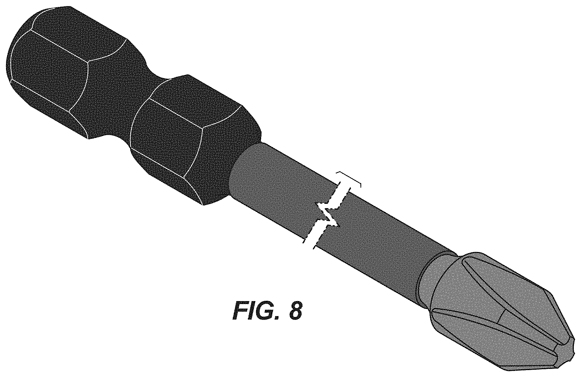
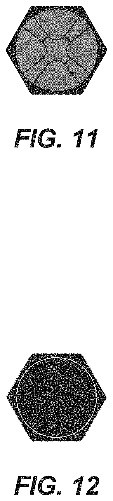
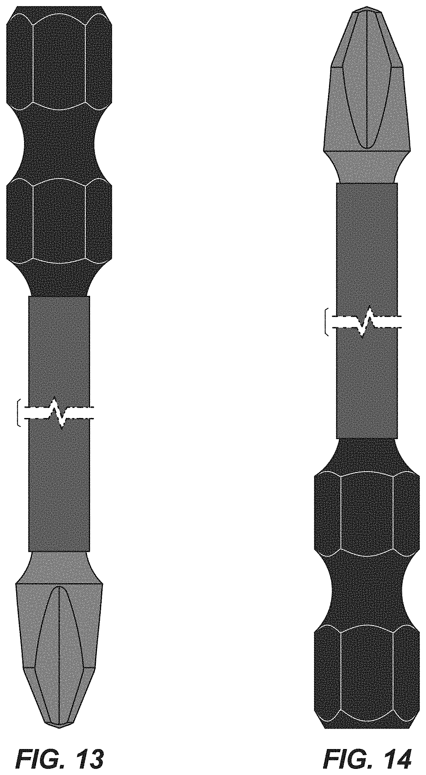
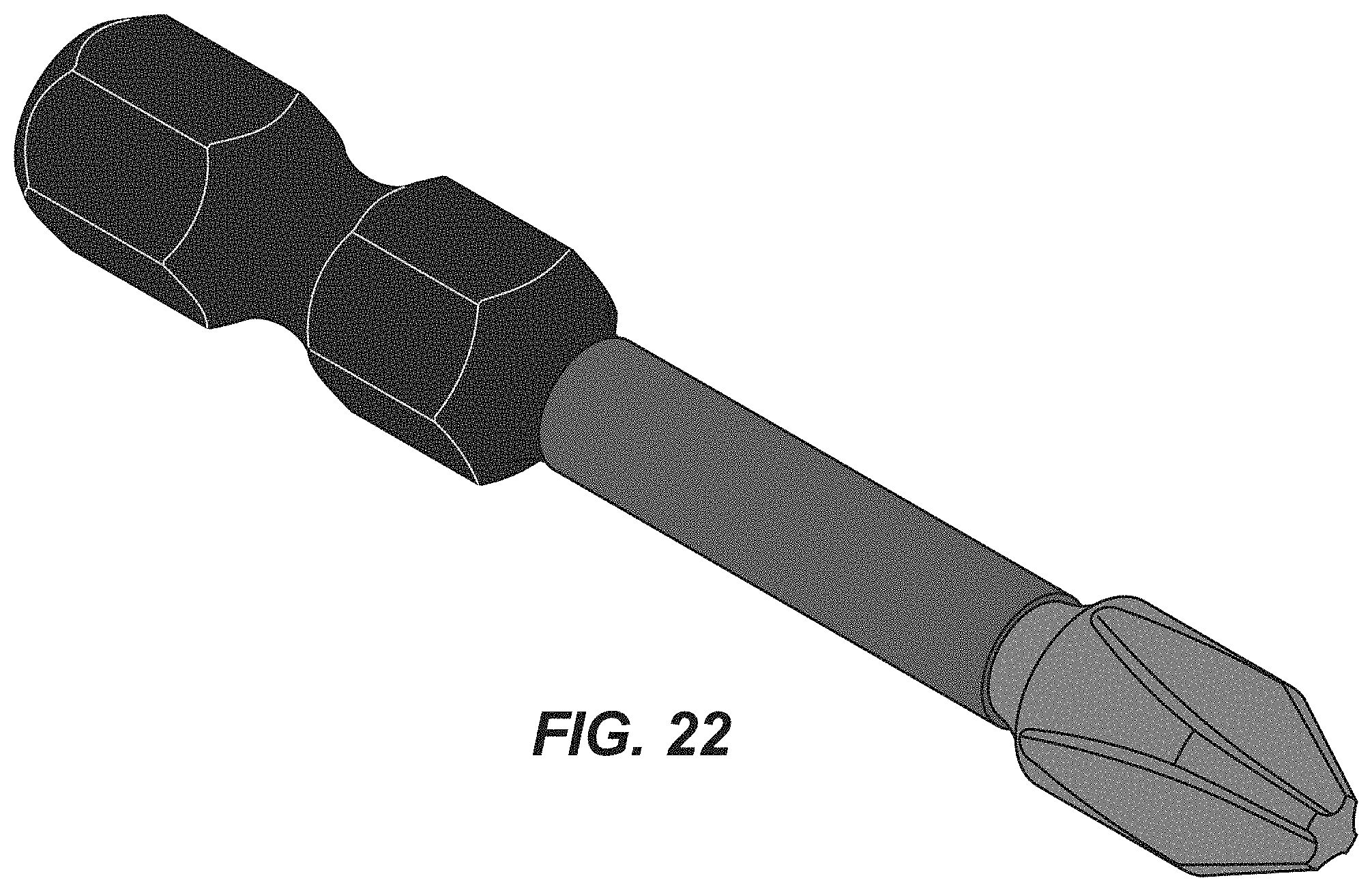
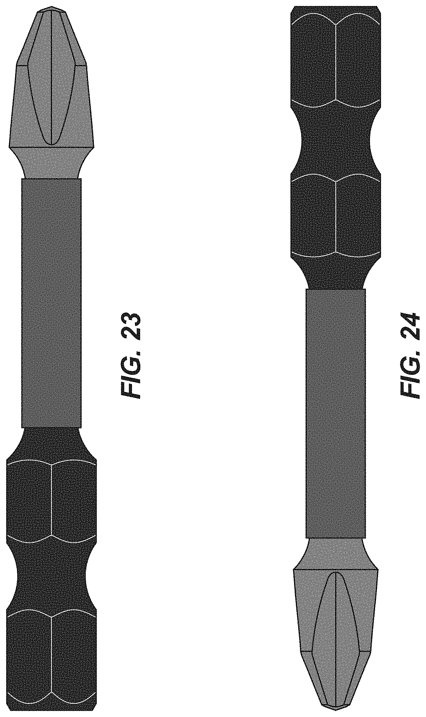
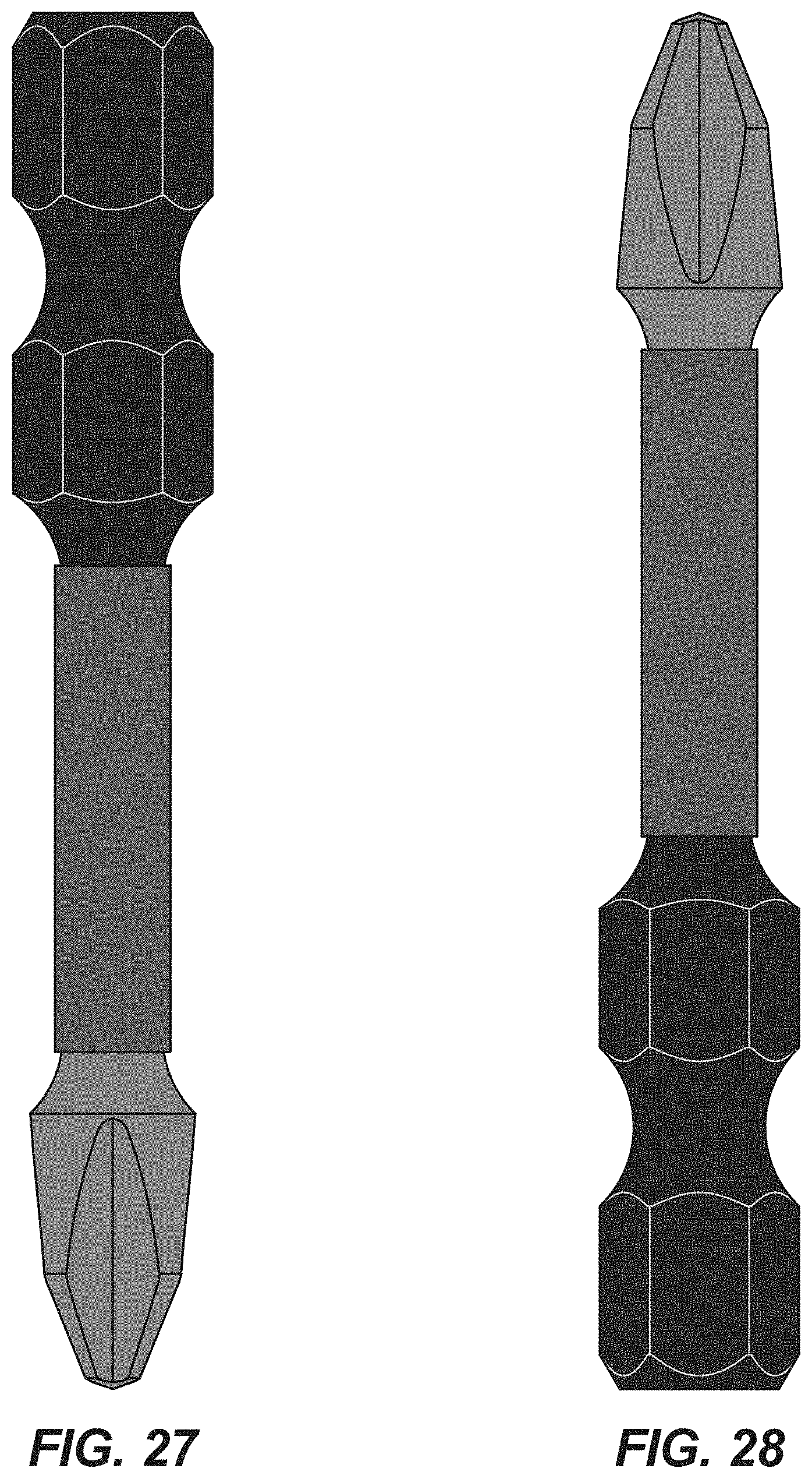
The patent or application file contains a least one drawing executed in color. Copies of this patent or patent application publication with color drawings will be provided by the Office upon request and payment of the necessary fee. The black, red, and gray color shown in the embodiment of FIGS. 8-14 and 22-28 forms a part of the claimed design in the embodiment of FIGS. 8-14 and FIGS. 22-28.
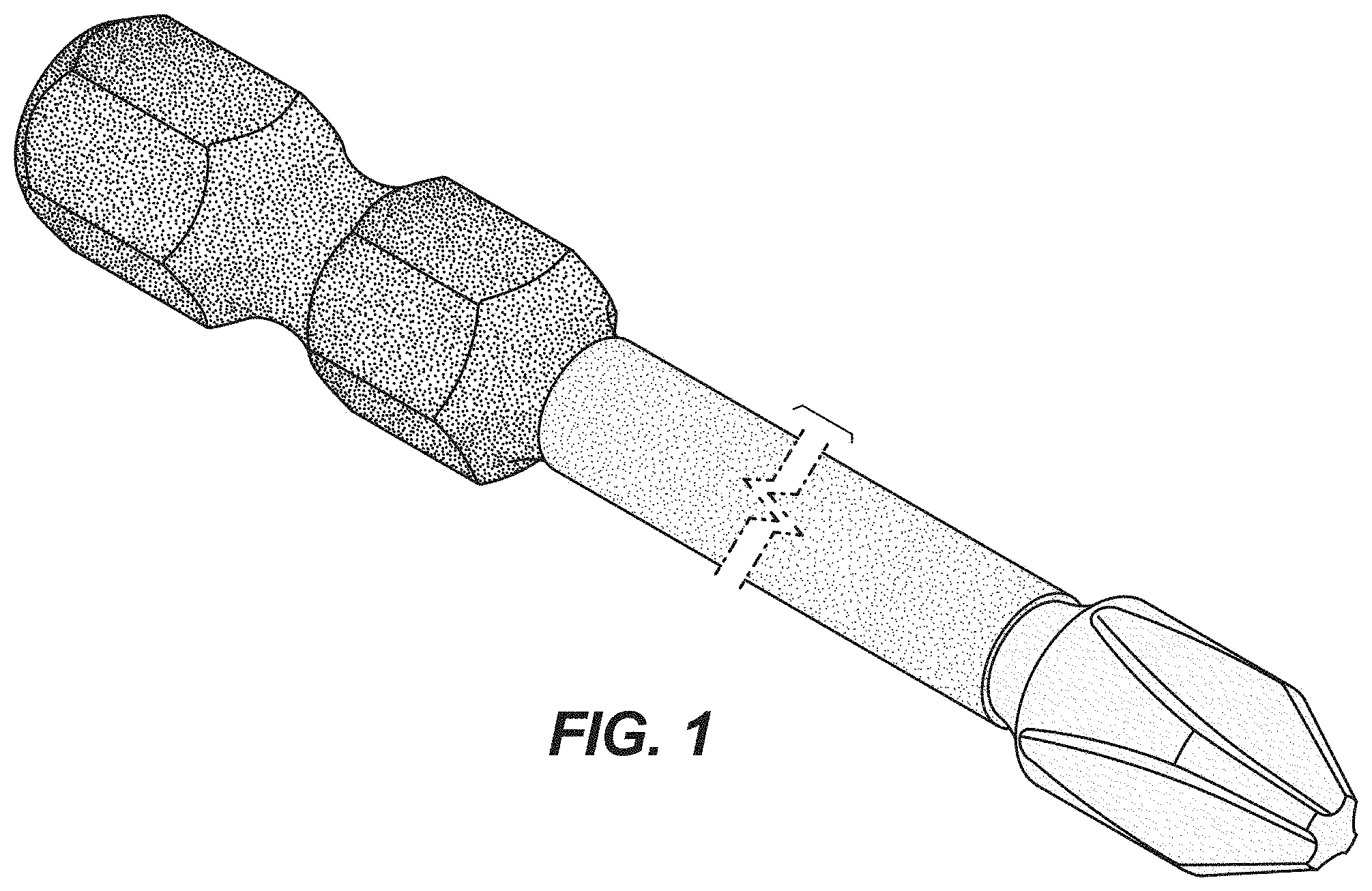
FIG. 1 is a perspective view of a driver bit embodying the invention.
FIG. 2 is a first side view of the driver bit of FIG. 1.
FIG. 3 is a second side view of the driver bit of FIG. 1.
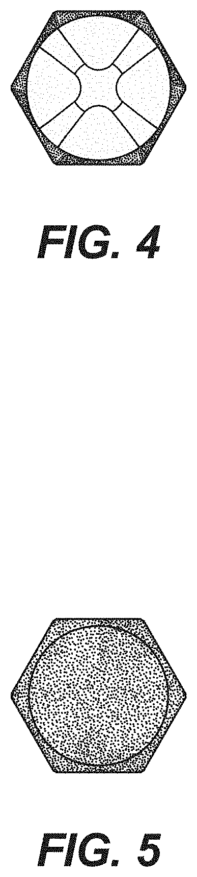
FIG. 4 is a first end view of the driver bit and of FIG. 1.
FIG. 5 is a second end view of the driver bit of FIG. 1.
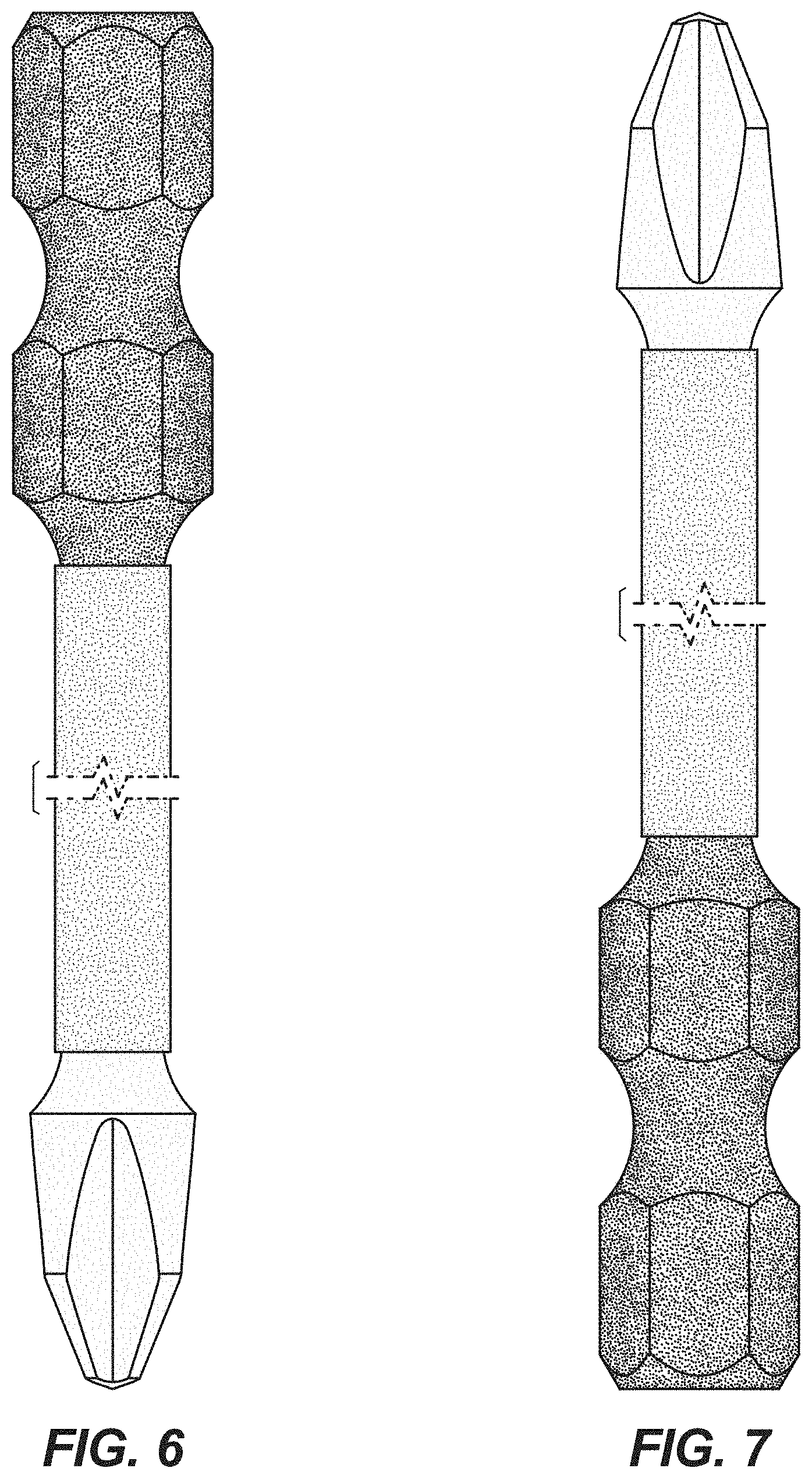
FIG. 6 is a third side view of the driver bit of FIG. 1.
FIG. 7 is a fourth side view of the driver bit of FIG. 1.
FIG. 8 is a perspective view of another driver bit embodying the invention.
FIG. 9 is a first side view of the driver bit of FIG. 8.
FIG. 10 is a second side view of the driver bit of FIG. 8.
FIG. 11 is a first end view of the driver bit of FIG. 8.
FIG. 12 is a second end view of the driver bit of FIG. 8.
FIG. 13 is a third side view of the driver bit of FIG. 8.
FIG. 14 is a fourth side view of the driver bit of FIG. 8.
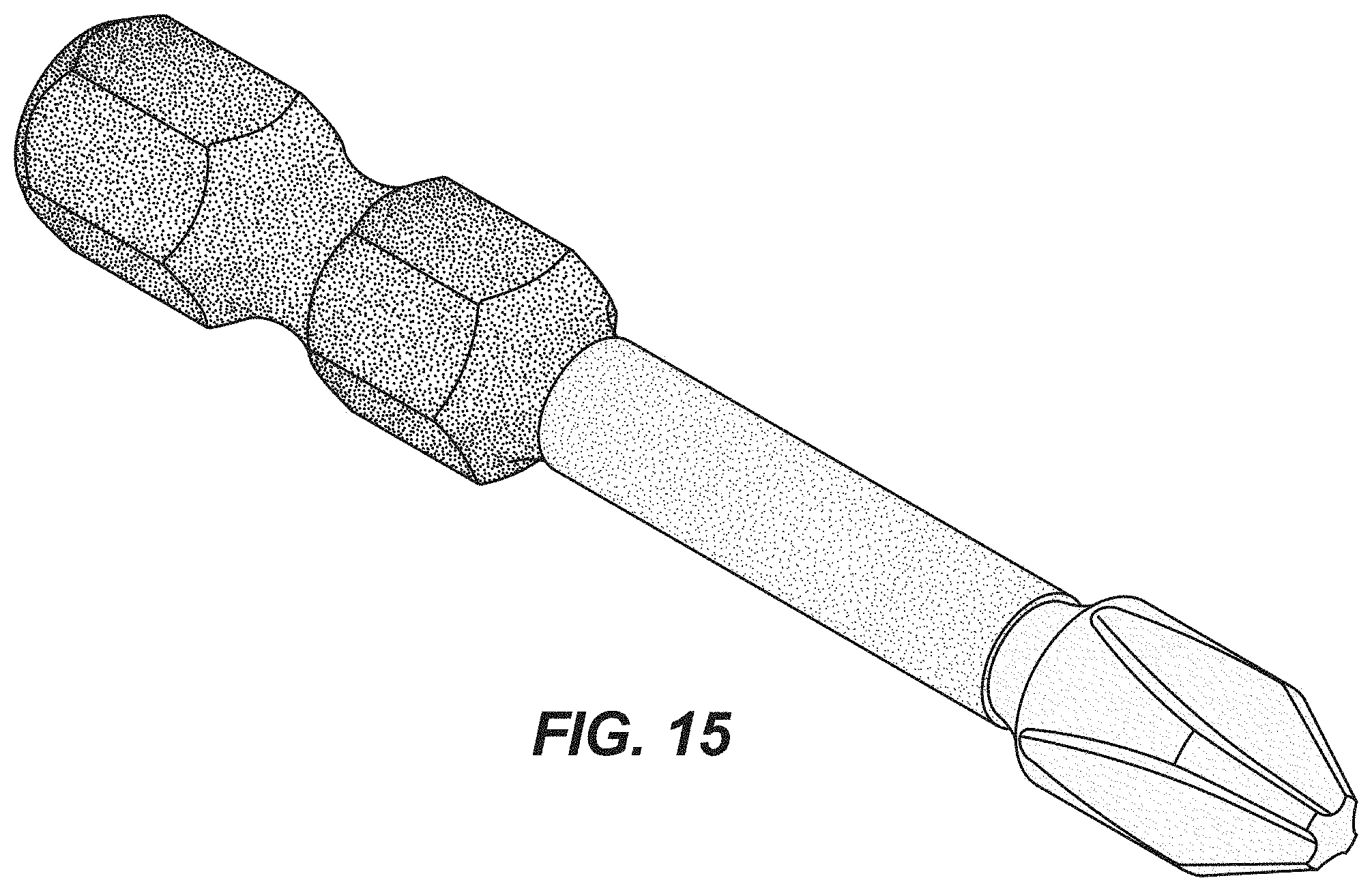
FIG. 15 is a perspective view of another driver bit embodying the invention.
FIG. 16 is a first side view of the driver bit of FIG. 15.
FIG. 17 is a second side view of the driver bit of FIG. 15.
FIG. 18 is a first end view of the driver bit of FIG. 15.
FIG. 19 is a second end view of the driver bit of FIG. 15.
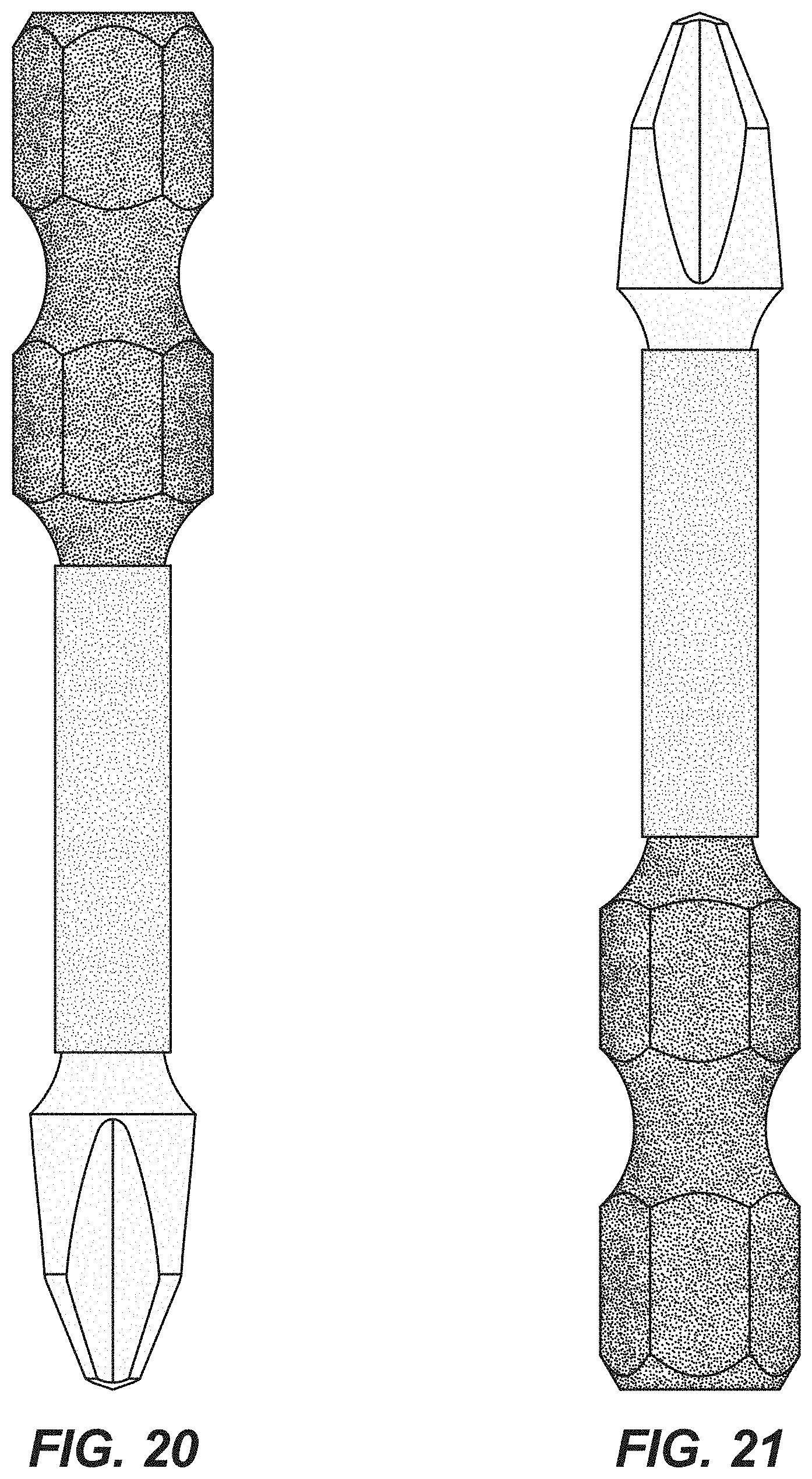
FIG. 20 is a third side view of the driver bit of FIG. 15.
FIG. 21 is a fourth side view of the driver bit of FIG. 15.
FIG. 22 is a perspective view of another driver bit embodying the invention.
FIG. 23 is a first side view of the driver bit of FIG. 22.
FIG. 24 is a second side view of the driver bit of FIG. 22.
FIG. 25 is a first end view of the driver bit of FIG. 22.
FIG. 26 is a second end view of the driver bit of FIG. 22.
FIG. 27 is a third side view of the driver bit of FIG. 22; and,
FIG. 28 is a fourth side view of the driver bit of FIG. 22.
The long and short broken lines indicate boundaries which form no part of the claimed design.
The different stippling intensities in FIGS. 1-7 and 15-21 represent contrasts in color appearance and not stipple patterns on the driver bits.
* * * * *
D00000
D00001
D00002
D00003
D00004
D00005
D00006
D00007
D00008
D00009
D00010
D00011
D00012
D00013
D00014
D00015

D00016
XML
uspto.report is an independent third-party trademark research tool that is not affiliated, endorsed, or sponsored by the United States Patent and Trademark Office (USPTO) or any other governmental organization. The information provided by uspto.report is based on publicly available data at the time of writing and is intended for informational purposes only.
While we strive to provide accurate and up-to-date information, we do not guarantee the accuracy, completeness, reliability, or suitability of the information displayed on this site. The use of this site is at your own risk. Any reliance you place on such information is therefore strictly at your own risk.
All official trademark data, including owner information, should be verified by visiting the official USPTO website at www.uspto.gov. This site is not intended to replace professional legal advice and should not be used as a substitute for consulting with a legal professional who is knowledgeable about trademark law.