Conduit coupler
Provenzano , et al. December 22, 2
U.S. patent number D905,831 [Application Number D/669,313] was granted by the patent office on 2020-12-22 for conduit coupler. This patent grant is currently assigned to Electronic Custom Distributors, Inc.. The grantee listed for this patent is ELECTRONIC CUSTOM DISTRIBUTORS, INC.. Invention is credited to Michael Leung, Charles J. Provenzano.


| United States Patent | D905,831 |
| Provenzano , et al. | December 22, 2020 |
Conduit coupler
Claims
CLAIM The ornamental design for a conduit coupler, as shown and described.
| Inventors: | Provenzano; Charles J. (Houston, TX), Leung; Michael (Missouri City, TX) | ||||||||||
|---|---|---|---|---|---|---|---|---|---|---|---|
| Applicant: |
|
||||||||||
| Assignee: | Electronic Custom Distributors,
Inc. (Houston, TX) |
||||||||||
| Appl. No.: | D/669,313 | ||||||||||
| Filed: | November 7, 2018 |
| Current U.S. Class: | D23/262 |
| Current International Class: | 2301 |
| Field of Search: | ;D23/259-260,262,264-266 ;D8/382,387,394,396-397 ;D13/133,50,154-156 ;285/345,377,388,390 ;439/246,256-257,483 |
References Cited [Referenced By]
U.S. Patent Documents
| D299267 | January 1989 | Roman |
| D363767 | October 1995 | Swaim |
| 7364450 | April 2008 | Hafner |
| 7503788 | March 2009 | Holterhoff |
| D701494 | March 2014 | Errato, Jr. |
| D774628 | December 2016 | Provenzano |
| D834531 | November 2018 | Maroney |
| D839213 | January 2019 | Maroney |
| D852334 | June 2019 | Sfredel |
| D859973 | September 2019 | Foerster, Jr. |
| D880423 | April 2020 | Obata |
| 2012/0200081 | August 2012 | Reznar |
| 2019/0330947 | October 2019 | Mulhern |
Other References
|
DCPC100ADC DirectConnect 1'' Conduit Adapter to 2'' Nut Coupler; ECD, Inc Website Copyright Date 2020; Visited Online Jun. 11, 2020 ; https://www.ecdcom.com/index.jsp?path=product&part=34817&ds=dept&process=- search&qdx=0&ID=%2CNetwork%2CTelecom%2Cdept-1M5 (Year: 2020). cited by examiner. |
Primary Examiner: Wierenga; Amy C
Attorney, Agent or Firm: Scott; Mark E. Dickinson Wright PLLC
Description
FIG. 1 is a perspective view of a conduit coupler showing the new design;
FIG. 2 is a first side view thereof with a nut attached;
FIG. 3 is a second side view thereof with the nut attached, the second side view opposite the first side view;
FIG. 4 is a top view thereof;
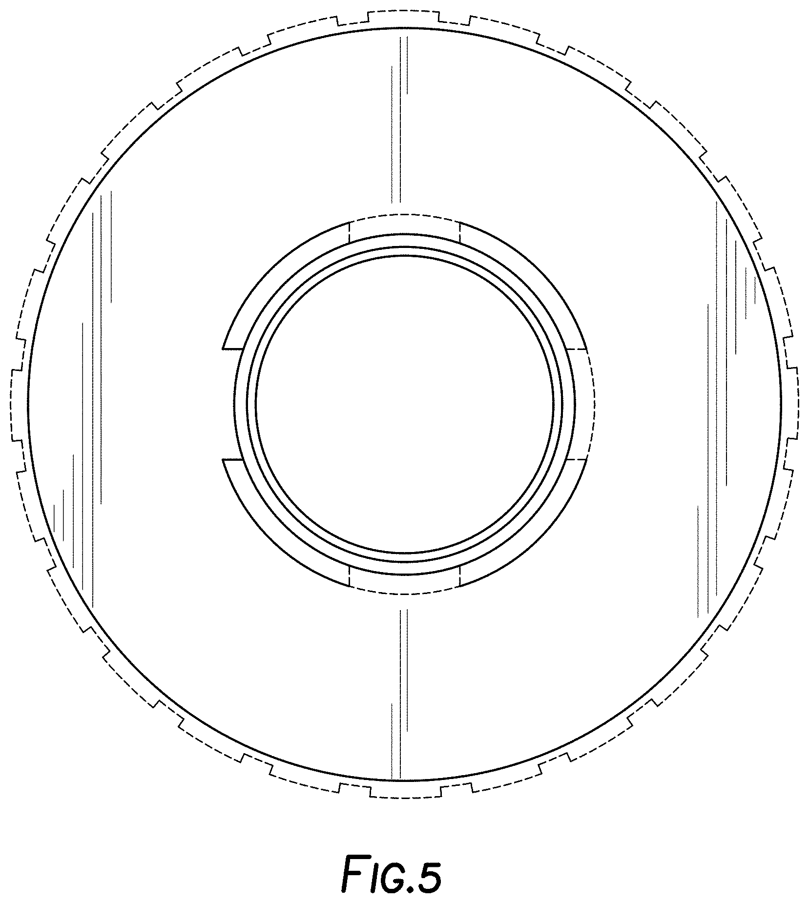
FIG. 5 is a bottom view thereof;
FIG. 6 is the first side view as shown in FIG. 2 with the nut removed; and,
FIG. 7 is a perspective view showing the conduit coupler in a position of use in an example environment.
The broken lines shown in the drawings represent portions of the conduit coupler and environment that form no part of the claim.
* * * * *
References
D00000
D00001
D00002
D00003
D00004
D00005
D00006
D00007
XML
uspto.report is an independent third-party trademark research tool that is not affiliated, endorsed, or sponsored by the United States Patent and Trademark Office (USPTO) or any other governmental organization. The information provided by uspto.report is based on publicly available data at the time of writing and is intended for informational purposes only.
While we strive to provide accurate and up-to-date information, we do not guarantee the accuracy, completeness, reliability, or suitability of the information displayed on this site. The use of this site is at your own risk. Any reliance you place on such information is therefore strictly at your own risk.
All official trademark data, including owner information, should be verified by visiting the official USPTO website at www.uspto.gov. This site is not intended to replace professional legal advice and should not be used as a substitute for consulting with a legal professional who is knowledgeable about trademark law.