Machine for earth-moving, material handling, lifting, and/or construction
Watson , et al. December 1, 2
U.S. patent number D903,969 [Application Number D/706,335] was granted by the patent office on 2020-12-01 for machine for earth-moving, material handling, lifting, and/or construction. This patent grant is currently assigned to J.C. BAMFORD EXCAVATORS LIMITED. The grantee listed for this patent is J.C. BAMFORD EXCAVATORS LIMITED. Invention is credited to Louis Gospel, Steve Newberry, Ben Watson.


| United States Patent | D903,969 |
| Watson , et al. | December 1, 2020 |
Machine for earth-moving, material handling, lifting, and/or construction
Claims
CLAIM The ornamental design for a machine for earth-moving, material handling, lifting, and/or construction, as shown and described.
| Inventors: | Watson; Ben (Uttoxeter, GB), Gospel; Louis (Uttoxeter, GB), Newberry; Steve (Uttoxeter, GB) | ||||||||||
|---|---|---|---|---|---|---|---|---|---|---|---|
| Applicant: |
|
||||||||||
| Assignee: | J.C. BAMFORD EXCAVATORS LIMITED
(Uttoxeter, GB) |
||||||||||
| Appl. No.: | D/706,335 | ||||||||||
| Filed: | September 19, 2019 |
Foreign Application Priority Data
| Mar 26, 2019 [WO] | DM202419 | |||
| Current U.S. Class: | D34/34; D34/35; D15/28 |
| Current International Class: | 1205 |
| Field of Search: | ;D34/34,35,28,33,37 ;D15/28,22-26 ;296/190,202 ;37/341,442 ;414/529,572,718,785,607 |
References Cited [Referenced By]
U.S. Patent Documents
| D231975 | July 1974 | Aiello et al. |
| D316468 | April 1991 | Sandrock |
| 5199861 | April 1993 | Merlo |
| D366489 | January 1996 | Brown |
| D376243 | December 1996 | Magni |
| 5687809 | November 1997 | Braud |
| 5836733 | November 1998 | Moses |
| D438359 | February 2001 | Braud |
| D460085 | July 2002 | Crookes |
| D461831 | August 2002 | Laberheim |
| D480529 | October 2003 | Pini |
| D609721 | February 2010 | Schmidt |
| D610170 | February 2010 | Schmidt |
| D634757 | March 2011 | Mack |
| D668271 | October 2012 | Hutchinson |
| D723240 | February 2015 | Gonzales |
| D756057 | May 2016 | Nessler |
| D855659 | August 2019 | Kasaba |
Attorney, Agent or Firm: Marshall, Gerstein & Borun LLP
Description
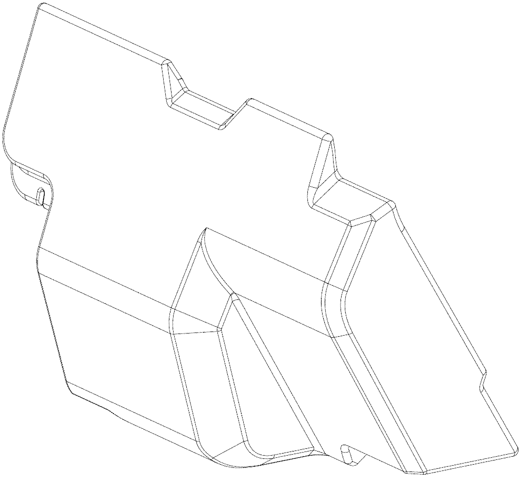
FIG. 1 is a top, front, and right-side isometric view of a machine for earth-moving, material handling, lifting, and/or construction showing the new design.
FIG. 2 is an enlarged top, front, and right-side isometric view of the part of the machine that bears the claimed design.
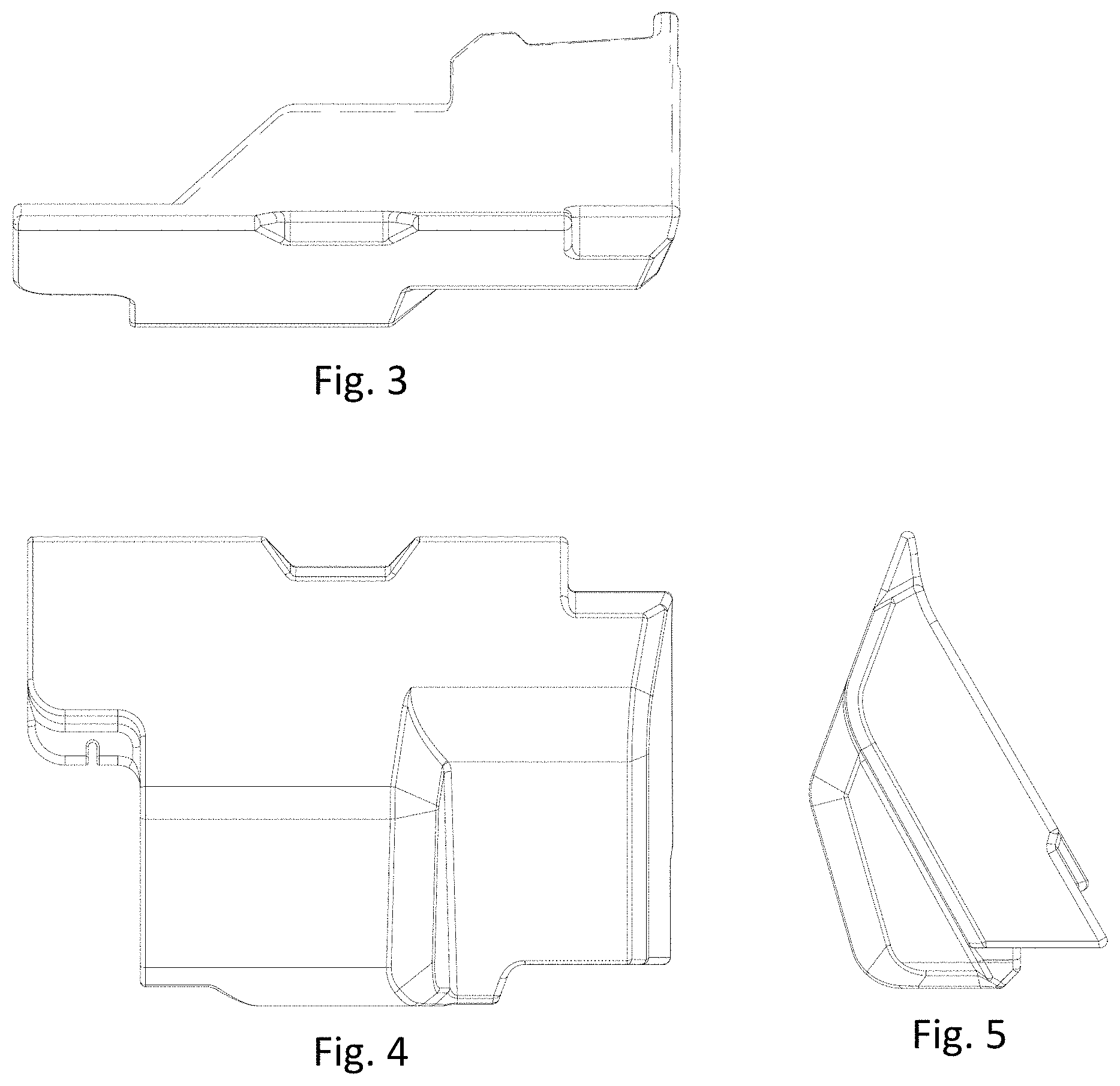
FIG. 3 is a top plan view of the part seen in FIG. 2.
FIG. 4 is a front elevation view of the part seen in FIG. 2.
FIG. 5 is a right-side elevation view of the part seen in FIG. 2.
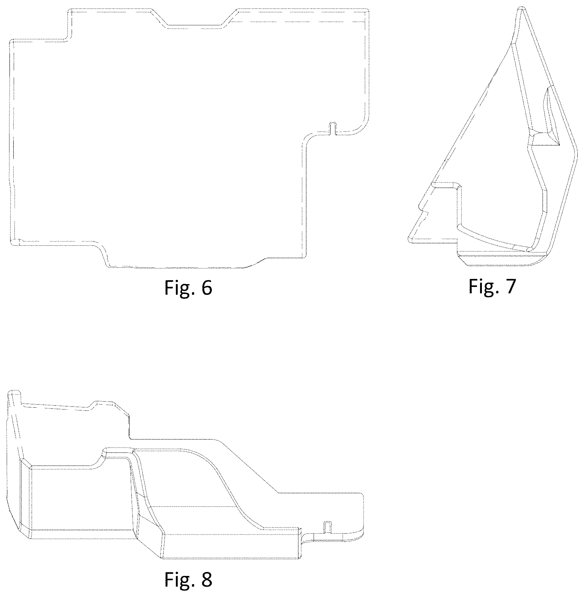
FIG. 6 is a rear elevation view of the part seen in FIG. 2.
FIG. 7 is a left-side elevation view of the part seen in FIG. 2; and,
FIG. 8 is a bottom plan view of the part seen in FIG. 2.
The broken lines depict portions of the machine for earth-moving, material handling, lifting, and/or construction that form no part of the claimed design.
* * * * *
D00000
D00001
D00002
D00003
D00004
XML
uspto.report is an independent third-party trademark research tool that is not affiliated, endorsed, or sponsored by the United States Patent and Trademark Office (USPTO) or any other governmental organization. The information provided by uspto.report is based on publicly available data at the time of writing and is intended for informational purposes only.
While we strive to provide accurate and up-to-date information, we do not guarantee the accuracy, completeness, reliability, or suitability of the information displayed on this site. The use of this site is at your own risk. Any reliance you place on such information is therefore strictly at your own risk.
All official trademark data, including owner information, should be verified by visiting the official USPTO website at www.uspto.gov. This site is not intended to replace professional legal advice and should not be used as a substitute for consulting with a legal professional who is knowledgeable about trademark law.