Medical monitoring device
Rihu , et al. November 10, 2
U.S. patent number D901,692 [Application Number D/629,657] was granted by the patent office on 2020-11-10 for medical monitoring device. This patent grant is currently assigned to BIOVOTION AG. The grantee listed for this patent is BIOVOTION AG. Invention is credited to Andreas Caduff, Antti Eskeli, Jussi Juva, Niki Kurki, Atte Peltola, Veikko Rihu.


View All Diagrams
| United States Patent | D901,692 |
| Rihu , et al. | November 10, 2020 |
Medical monitoring device
Claims
CLAIM The ornamental design for a medical monitoring device, as shown and described.
| Inventors: | Rihu; Veikko (Turku, FI), Juva; Jussi (Turku, FI), Eskeli; Antti (Turku, FI), Peltola; Atte (Turku, FI), Kurki; Niki (Turku, FI), Caduff; Andreas (Schmerikon, CH) | ||||||||||
|---|---|---|---|---|---|---|---|---|---|---|---|
| Applicant: |
|
||||||||||
| Assignee: | BIOVOTION AG (Zurich,
CH) |
||||||||||
| Appl. No.: | D/629,657 | ||||||||||
| Filed: | December 14, 2017 |
Related U.S. Patent Documents
| Application Number | Filing Date | Patent Number | Issue Date | ||
|---|---|---|---|---|---|
| 35501817 | May 13, 2016 | D854162 | |||
| Current U.S. Class: | D24/167 |
| Current International Class: | 2402 |
| Field of Search: | ;D24/167,166,186,187 ;D10/32,70 ;D14/344 |
References Cited [Referenced By]
U.S. Patent Documents
| D701504 | March 2014 | Christopher |
| D703204 | April 2014 | Riddiford |
| D749570 | February 2016 | Lee |
| D751550 | March 2016 | Solomon |
| D755786 | May 2016 | Lapetina |
| D760717 | July 2016 | Solomon |
| D784325 | April 2017 | Kim |
| D787511 | May 2017 | Lee |
Description
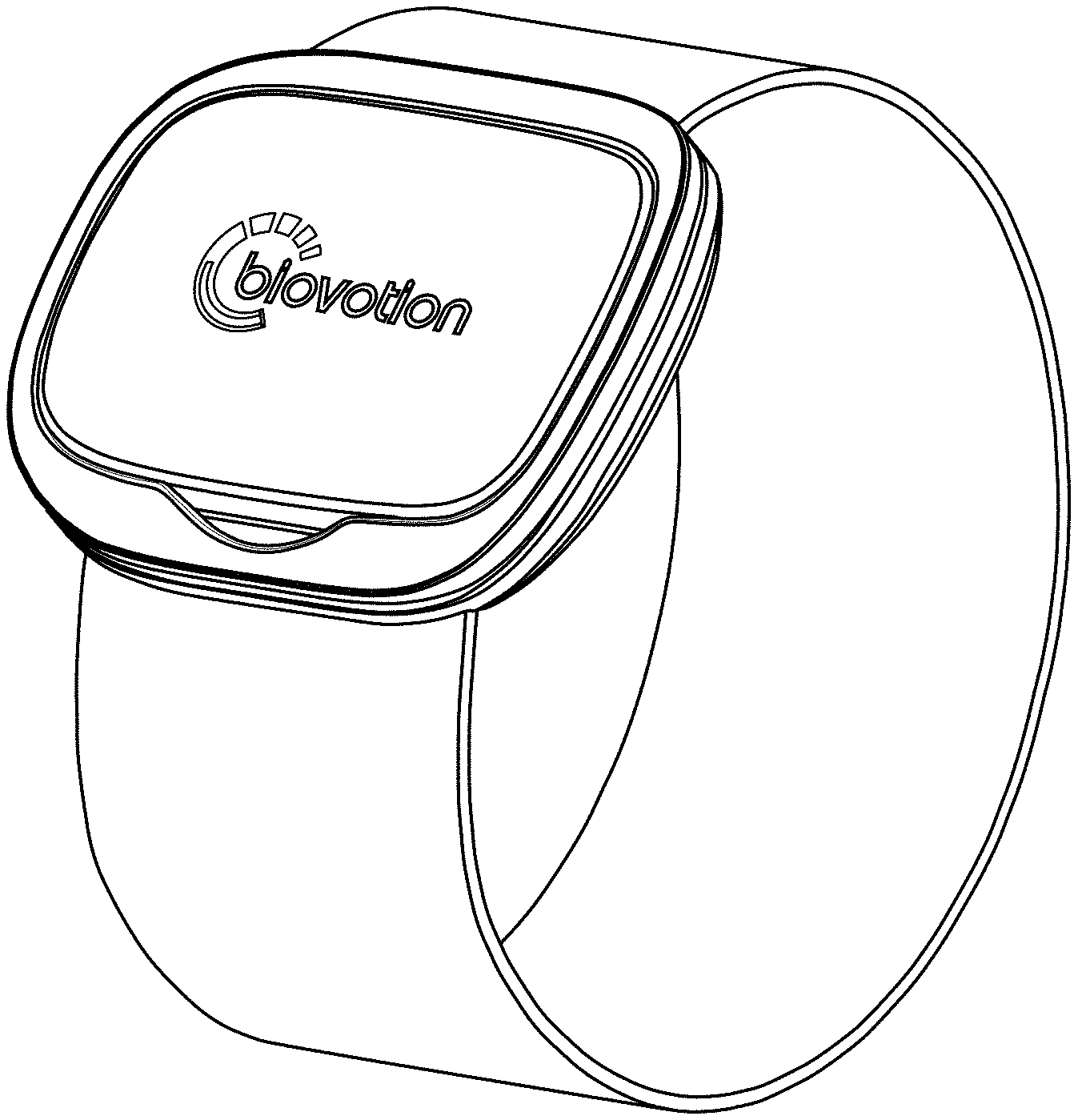
FIG. 1 is a perspective view in a closed configuration of a medical monitoring device embodying our new design;
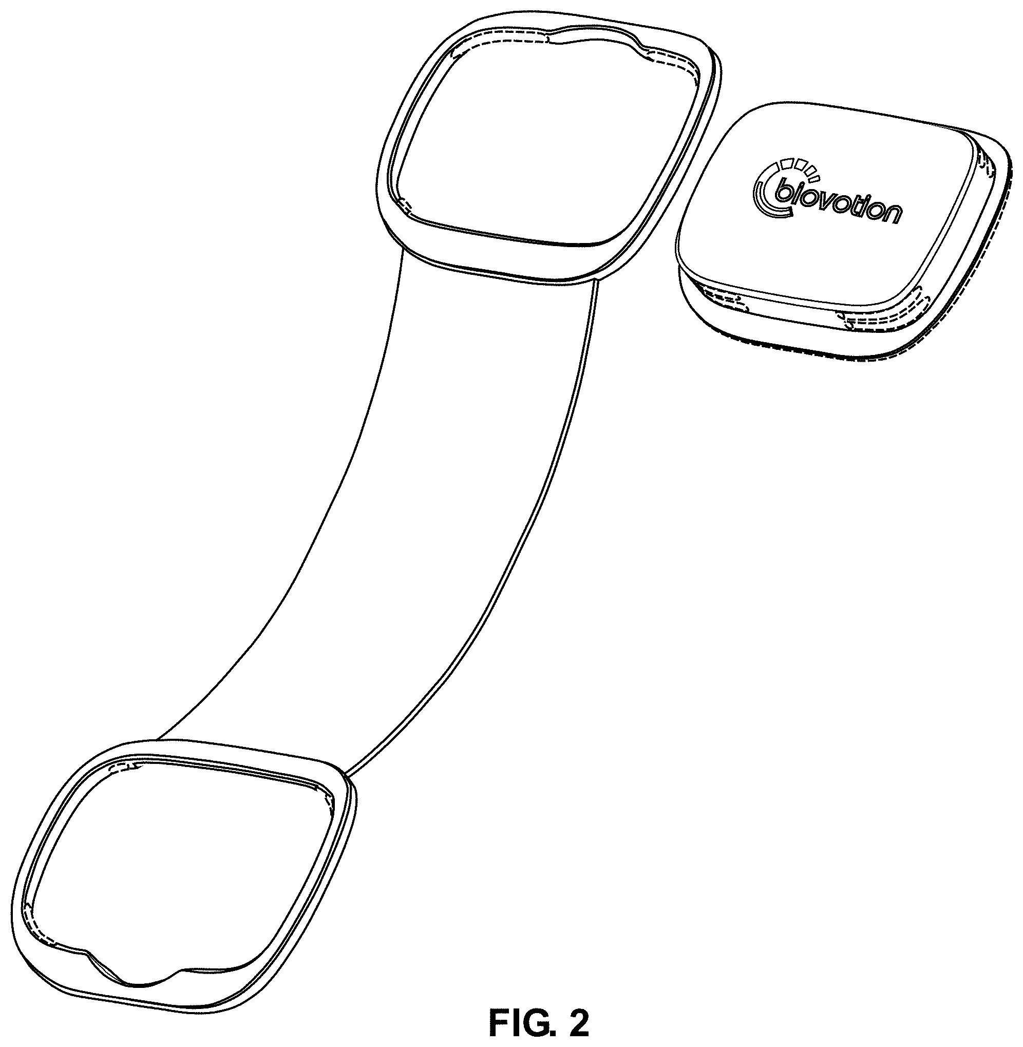
FIG. 2 is an exploded perspective view in an open configuration thereof;
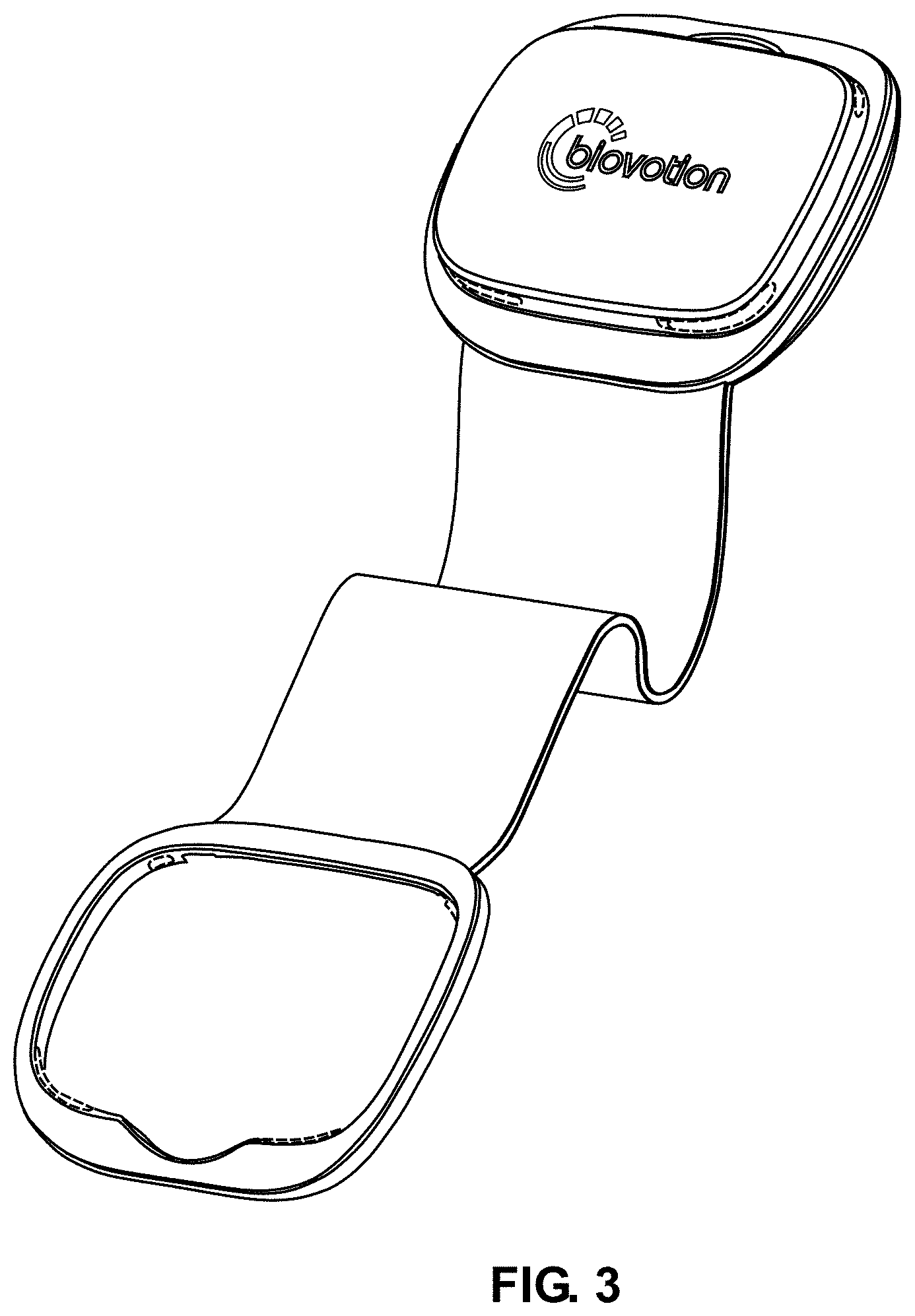
FIG. 3 is a perspective view in an open configuration thereof;
FIG. 4 is a top view thereof;
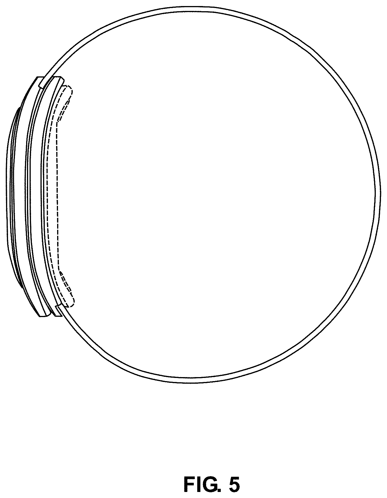
FIG. 5 is a right side view thereof in a closed configuration, the left side view being a mirror thereof;
FIG. 6 is a top view thereof in an open configuration;
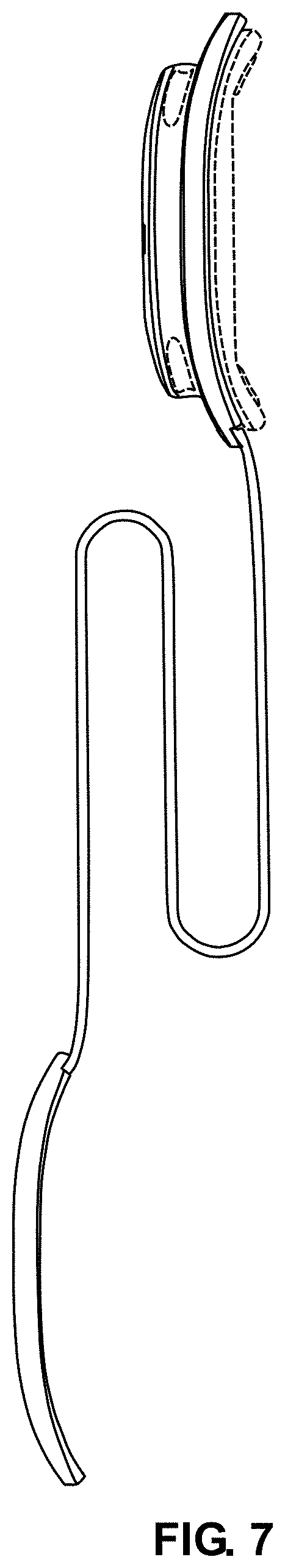
FIG. 7 is a right side view thereof in an open configuration;
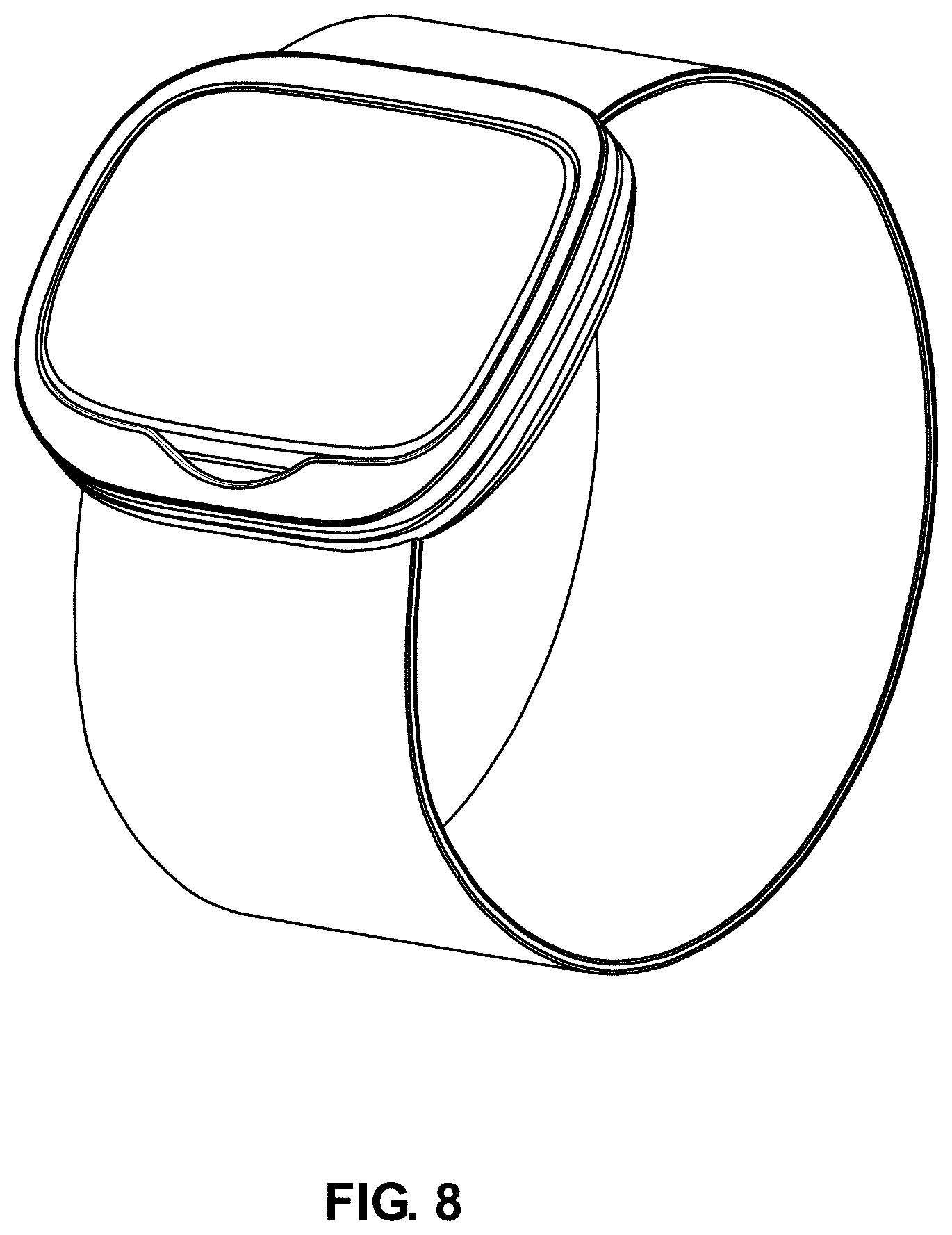
FIG. 8 is a perspective view in a closed configuration of a medical monitoring device embodying our new design;
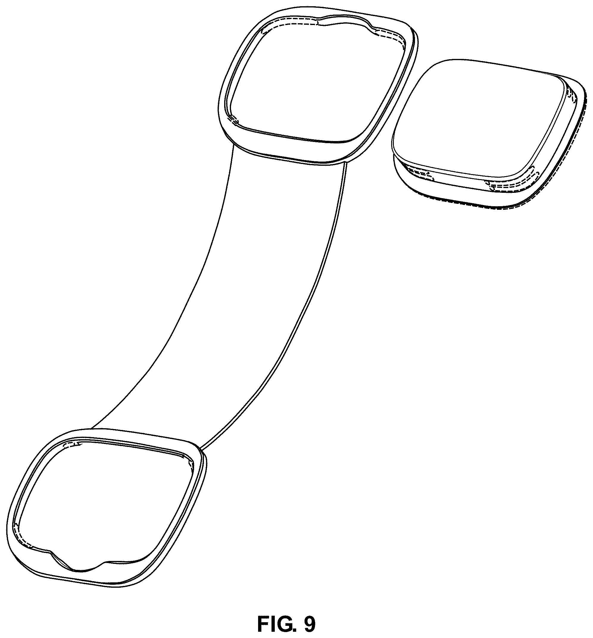
FIG. 9 is an exploded perspective view in an open configuration thereof;
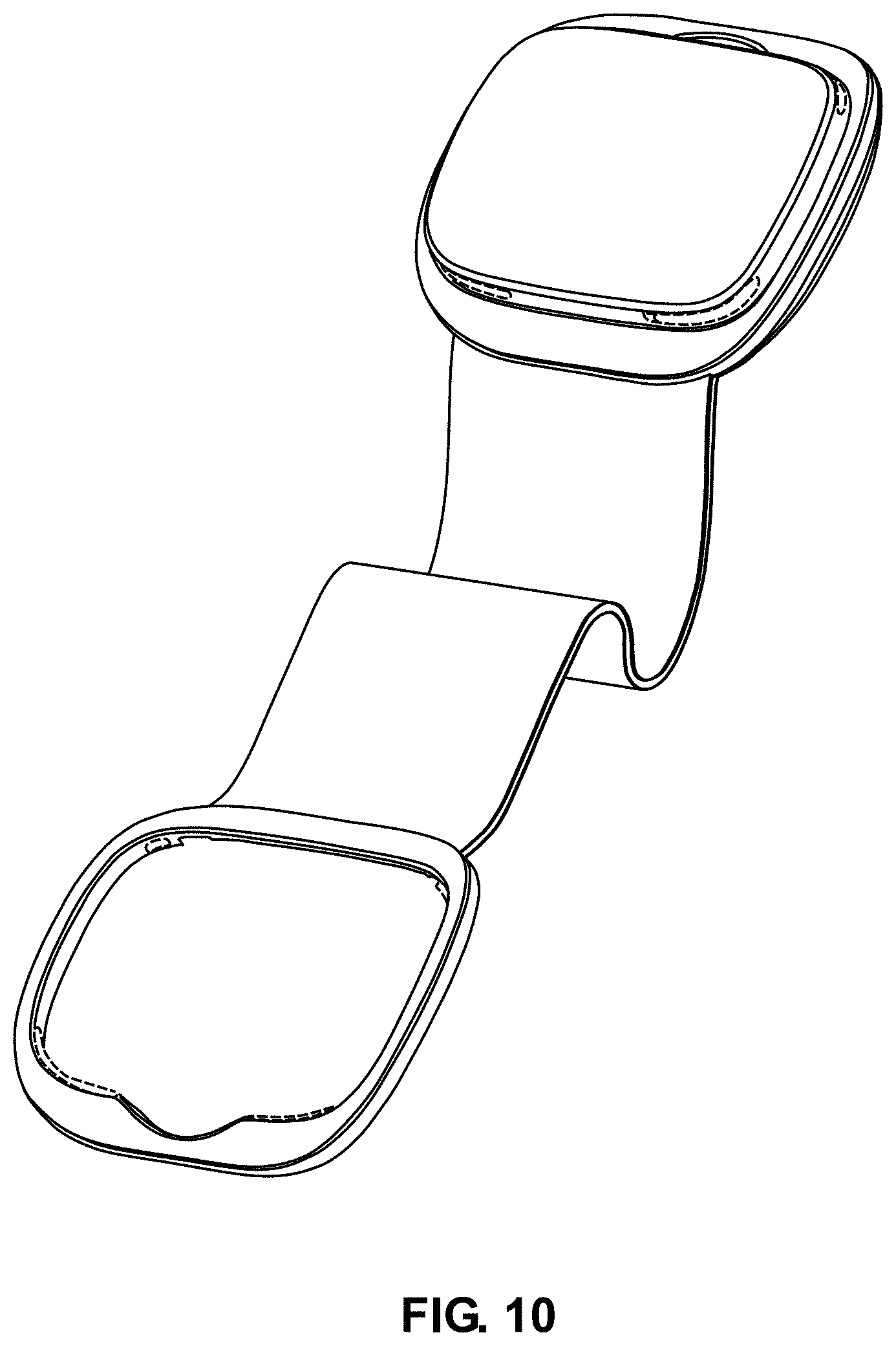
FIG. 10 is a perspective view in an open configuration thereof;
FIG. 11 is a top view thereof;
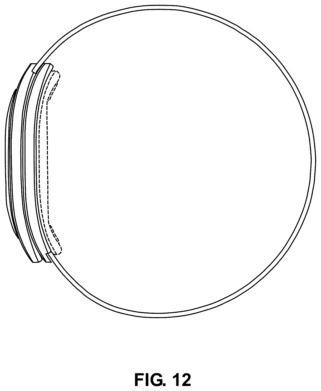
FIG. 12 is a right side view thereof in a closed configuration, the left side view being a mirror thereof;
FIG. 13 is a top view thereof in an open configuration; and,
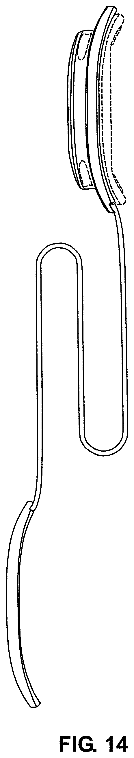
FIG. 14 is a right side view thereof in an open configuration.
The portions of the article shown in broken lines in the drawing form no part of the claimed design.
* * * * *
D00000
D00001
D00002
D00003
D00004
D00005
D00006
D00007
D00008
D00009
D00010
D00011
D00012
D00013

D00014
XML
uspto.report is an independent third-party trademark research tool that is not affiliated, endorsed, or sponsored by the United States Patent and Trademark Office (USPTO) or any other governmental organization. The information provided by uspto.report is based on publicly available data at the time of writing and is intended for informational purposes only.
While we strive to provide accurate and up-to-date information, we do not guarantee the accuracy, completeness, reliability, or suitability of the information displayed on this site. The use of this site is at your own risk. Any reliance you place on such information is therefore strictly at your own risk.
All official trademark data, including owner information, should be verified by visiting the official USPTO website at www.uspto.gov. This site is not intended to replace professional legal advice and should not be used as a substitute for consulting with a legal professional who is knowledgeable about trademark law.