Signal converter
Aki , et al. November 10, 2
U.S. patent number D901,385 [Application Number D/697,947] was granted by the patent office on 2020-11-10 for signal converter. This patent grant is currently assigned to SMC CORPORATION. The grantee listed for this patent is SMC CORPORATION. Invention is credited to Tomohiko Aki, Yuko Kochi, Norimasa Ozaki.


| United States Patent | D901,385 |
| Aki , et al. | November 10, 2020 |
Signal converter
Claims
CLAIM The ornamental design for a signal converter, as shown and described.
| Inventors: | Aki; Tomohiko (Nagareyama, JP), Kochi; Yuko (Tsukubamirai, JP), Ozaki; Norimasa (Moriya, JP) | ||||||||||
|---|---|---|---|---|---|---|---|---|---|---|---|
| Applicant: |
|
||||||||||
| Assignee: | SMC CORPORATION (Tokyo,
JP) |
||||||||||
| Appl. No.: | D/697,947 | ||||||||||
| Filed: | July 12, 2019 |
Foreign Application Priority Data
| Jan 30, 2019 [JP] | 2019-001673 | |||
| Current U.S. Class: | D13/123 |
| Current International Class: | 1303 |
| Field of Search: | ;D13/184,123-132,112,118,146,152,153,154,173,175,178,199 ;D14/496,154,199 |
References Cited [Referenced By]
U.S. Patent Documents
| D254001 | January 1980 | Mayo |
| D259934 | July 1981 | Lovret |
| D333122 | February 1993 | Kamakura |
| D431526 | October 2000 | Nishio |
| D439220 | March 2001 | Mayo |
| D449579 | October 2001 | Goto |
| D450039 | November 2001 | Goto |
| 6498890 | December 2002 | Kimminau |
| D490080 | May 2004 | Alviar |
| D571822 | June 2008 | Madonna |
| D715741 | October 2014 | Dallmeyer |
| D816609 | May 2018 | Komuro |
| D869410 | December 2019 | Kochi |
| 1014184 | Jul 1998 | JP | |||
| 1573481 | Apr 2017 | JP | |||
| 300842023.0000 | Mar 2016 | KR | |||
| 13737-0001 | Dec 2002 | MX | |||
| WO-2013183272 | Dec 2013 | WO | |||
Other References
|
Ali Express. Link: https://www.aliexpress.com/i/4000263224079.html. Visited Aug. 27, 2020. HDMI to RF Coaxial Converter AV Adapter Box W/ Remote Control HDMI to RF HDMI to RF Signal Converter. (Year: 2020). cited by examiner. |
Primary Examiner: McVey; Lauren D
Attorney, Agent or Firm: Birch, Stewart, Kolasch & Birch, LLP
Description
FIG. 1 is a front, top and left side perspective view of a signal converter showing our new design;
FIG. 2 is a rear, bottom and right side perspective view thereof;
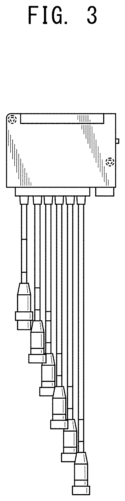
FIG. 3 is a front view thereof;
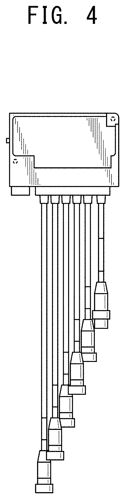
FIG. 4 is a rear view thereof;
FIG. 5 is a top plan view thereof;
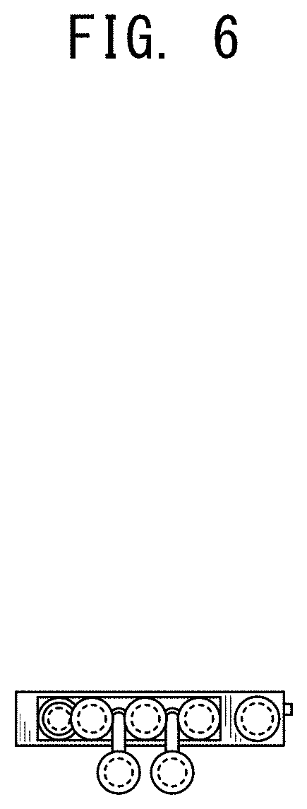
FIG. 6 is a bottom plan view thereof;
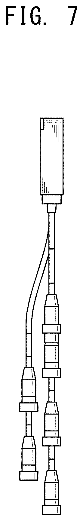
FIG. 7 is a left side view thereof; and,
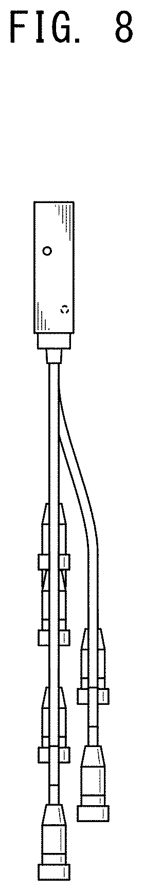
FIG. 8 is a right side view thereof.
The broken lines immediately adjacent to the claimed areas depict the bounds of the claimed design, while all other broken lines are directed to environment. The broken lines form no part of the claimed design.
* * * * *
References
D00000
D00001
D00002
D00003
D00004
D00005
D00006
D00007
D00008
XML
uspto.report is an independent third-party trademark research tool that is not affiliated, endorsed, or sponsored by the United States Patent and Trademark Office (USPTO) or any other governmental organization. The information provided by uspto.report is based on publicly available data at the time of writing and is intended for informational purposes only.
While we strive to provide accurate and up-to-date information, we do not guarantee the accuracy, completeness, reliability, or suitability of the information displayed on this site. The use of this site is at your own risk. Any reliance you place on such information is therefore strictly at your own risk.
All official trademark data, including owner information, should be verified by visiting the official USPTO website at www.uspto.gov. This site is not intended to replace professional legal advice and should not be used as a substitute for consulting with a legal professional who is knowledgeable about trademark law.