Flow detection device
Krywyj , et al. November 3, 2
U.S. patent number D900,656 [Application Number D/684,538] was granted by the patent office on 2020-11-03 for flow detection device. This patent grant is currently assigned to Orbis Intelligent Systems, Inc.. The grantee listed for this patent is Orbis Intelligent Systems, Inc.. Invention is credited to Daniel Milne Krywyj, Jeffrey A. Prsha.


| United States Patent | D900,656 |
| Krywyj , et al. | November 3, 2020 |
Flow detection device
Claims
CLAIM We claim the ornamental design for a flow detection device, as shown and described.
| Inventors: | Krywyj; Daniel Milne (La Jolla, CA), Prsha; Jeffrey A. (San Diego, CA) | ||||||||||
|---|---|---|---|---|---|---|---|---|---|---|---|
| Applicant: |
|
||||||||||
| Assignee: | Orbis Intelligent Systems, Inc.
(San Diego, CA) |
||||||||||
| Appl. No.: | D/684,538 | ||||||||||
| Filed: | March 21, 2019 |
| Current U.S. Class: | D10/96 |
| Current International Class: | 1004 |
| Field of Search: | ;D10/96 |
References Cited [Referenced By]
U.S. Patent Documents
| 7100440 | September 2006 | Morisawa |
| D708081 | July 2014 | Shibasaki |
Other References
|
US. Office Action dated Apr. 6, 2020 in U.S. Appl. No. 29/684,543. cited by applicant . Australian Office Action dated Nov. 8, 2019, issued in Australian Patent Application No. 201915471. cited by applicant . Chinese Office Action dated Apr. 13, 2020, issued in Chinese Patent Application No. 201930518844.9. cited by applicant . New Zealand Office Action dated Sep. 24, 2019, issued in New Zealand Patent Application No. 426574. cited by applicant . U.S. Appl. No. 29/684,543, filed Mar. 21, 2019, Krywyj et al. cited by applicant. |
Primary Examiner: Davis; Antoine Duval
Attorney, Agent or Firm: Weaver Austin Villeneuve & Sampson LLP
Description
FIG. 1 depicts an isometric view of a flow detection device.
FIG. 2 depicts a front view of the flow detection device of FIG. 1.
FIG. 3 depicts a back view of the flow detection device of FIG. 1.
FIG. 4 depicts a side view of the flow detection device of FIG. 1.
FIG. 5 depicts the other side view of the flow detection device of FIG. 1.
FIG. 6 depicts a top view of the flow detection device of FIG. 1.
FIG. 7 depicts a bottom view of the flow detection device of FIG. 1.
FIG. 8 depicts an off-angle view of the flow detection device of FIG. 1.
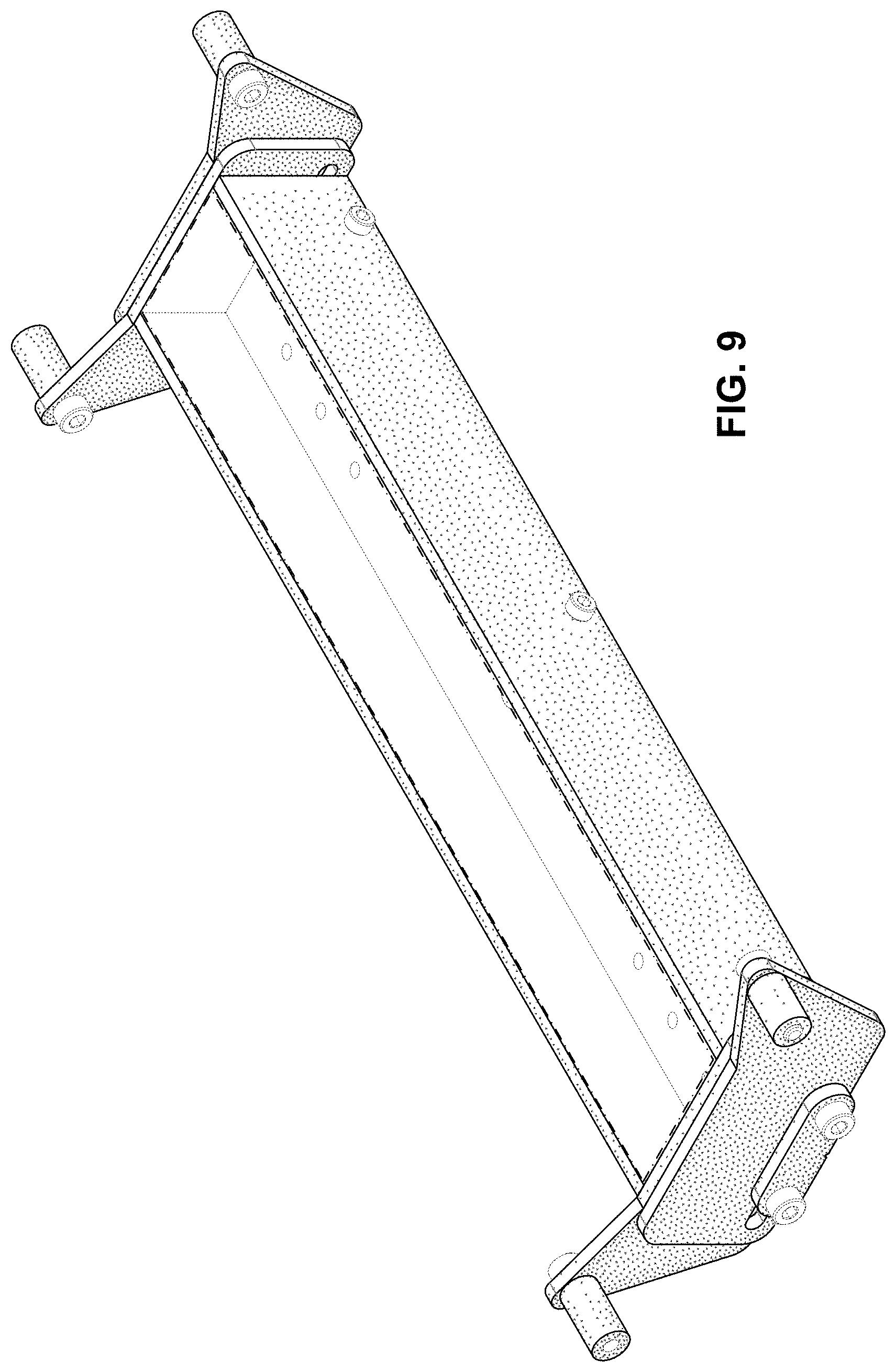
FIG. 9 depicts another off-angle view of the flow detection device of FIG. 1.
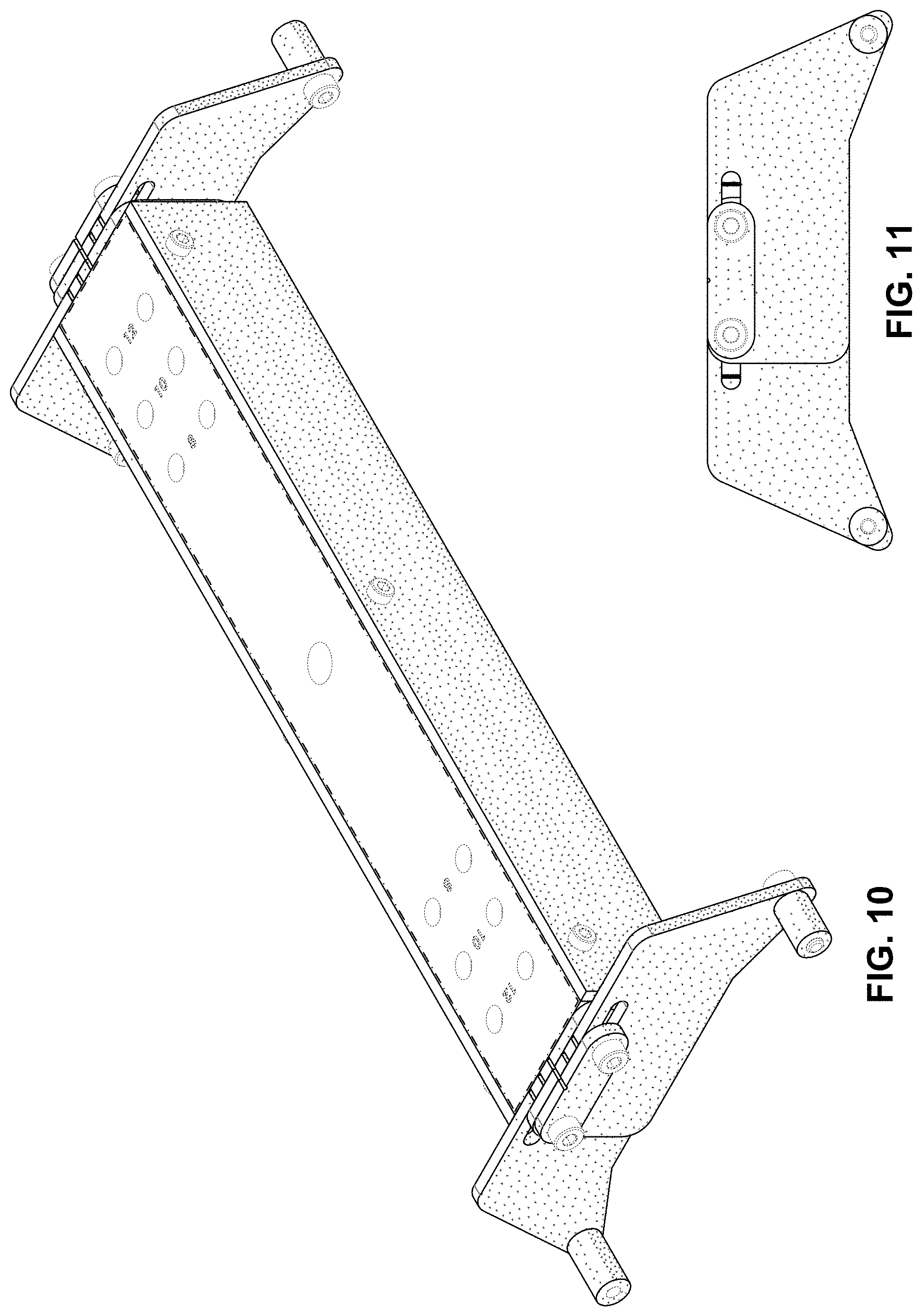
FIG. 10 depicts an isometric view of the flow detection device of FIG. 1 in a first adjusted position; each of the two plates at the front and back of the second flow detection device are adjustable to various positions.
FIG. 11 depicts a front view of the flow detection device of FIG. 10 in the first adjusted position.
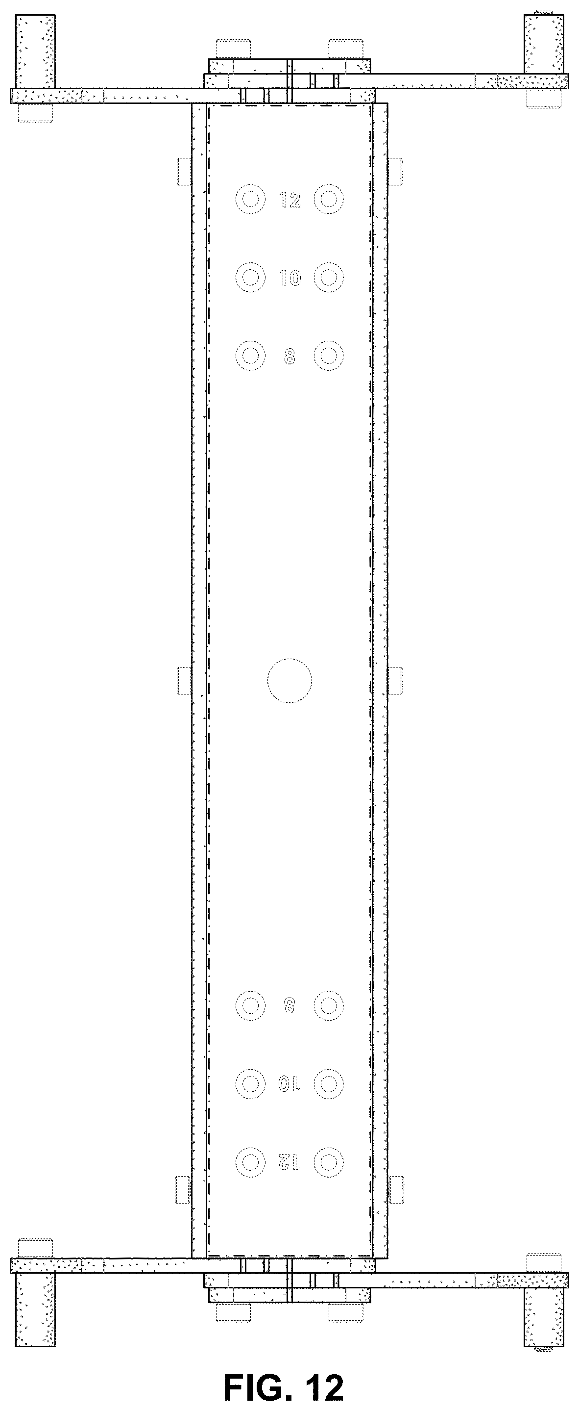
FIG. 12 depicts a top view of the flow detection device of FIG. 10 in the first adjusted position.
FIG. 13 depicts an off-angle view of the flow detection device of FIG. 10 in the first adjusted position.
FIG. 14 depicts an isometric exploded view of the flow detection device of FIG. 1; the scale of FIG. 14 reduced by 75% of FIG. 1.
The flow detection device in the accompanying figures may be positioned on a fluid conduit, such as a pipe, fire hydrant, or a standpipe.
Stipple shading is used in the accompanying Figures to convey surface contouring and not texture.
Broken lines are used to depict features or elements that are not considered to be part of the claimed design; the dash-dot-dash boundary line in FIGS. 1, 6-10, and 12-14 indicates a transition between claimed and unclaimed subject matter as evidenced by the absence of shading within the boundary shape and the presence of shading outside of the boundary shape.
* * * * *
D00000
D00001
D00002
D00003
D00004
D00005
D00006
D00007
D00008
D00009
XML
uspto.report is an independent third-party trademark research tool that is not affiliated, endorsed, or sponsored by the United States Patent and Trademark Office (USPTO) or any other governmental organization. The information provided by uspto.report is based on publicly available data at the time of writing and is intended for informational purposes only.
While we strive to provide accurate and up-to-date information, we do not guarantee the accuracy, completeness, reliability, or suitability of the information displayed on this site. The use of this site is at your own risk. Any reliance you place on such information is therefore strictly at your own risk.
All official trademark data, including owner information, should be verified by visiting the official USPTO website at www.uspto.gov. This site is not intended to replace professional legal advice and should not be used as a substitute for consulting with a legal professional who is knowledgeable about trademark law.