Imaging apparatus
Stalter , et al. October 13, 2
U.S. patent number D898,917 [Application Number D/684,551] was granted by the patent office on 2020-10-13 for imaging apparatus. This patent grant is currently assigned to GENERAL ELECTRIC COMPANY. The grantee listed for this patent is General Electric Company. Invention is credited to Timothy Behlmer, Jonathan Boutot, Kenwood P. Dayton, Brandon Smith, Michael Smith, Ross Christopher Stalter, Robert Surma.


View All Diagrams
| United States Patent | D898,917 |
| Stalter , et al. | October 13, 2020 |
Imaging apparatus
Claims
CLAIM The ornamental design for an imaging apparatus, as shown and described.
| Inventors: | Stalter; Ross Christopher (Hartland, WI), Smith; Michael (Whitewater, WI), Boutot; Jonathan (Waukesha, WI), Surma; Robert (Elm Grove, WI), Dayton; Kenwood P. (Mequon, WI), Smith; Brandon (Waukesha, WI), Behlmer; Timothy (Milwaukee, WI) | ||||||||||
|---|---|---|---|---|---|---|---|---|---|---|---|
| Applicant: |
|
||||||||||
| Assignee: | GENERAL ELECTRIC COMPANY
(Schenectady, NY) |
||||||||||
| Appl. No.: | D/684,551 | ||||||||||
| Filed: | March 21, 2019 |
Related U.S. Patent Documents
| Application Number | Filing Date | Patent Number | Issue Date | ||
|---|---|---|---|---|---|
| 29627198 | Nov 22, 2017 | D849949 | |||
| Current U.S. Class: | D24/158 |
| Current International Class: | 2401 |
| Field of Search: | ;D24/107,158-161,185,186,187,231 |
References Cited [Referenced By]
U.S. Patent Documents
| D432655 | October 2000 | Benders |
| D639950 | June 2011 | Ramos |
| D700339 | February 2014 | Tan |
| D700340 | February 2014 | Tan et al. |
| D700390 | February 2014 | Sabernig |
| D818126 | May 2018 | Personnelli |
| D849949 | May 2019 | Stalter |
| D874005 | January 2020 | Zhang |
Other References
|
Zhang, W. et al., "An Ornamental Design for an Imaging Appratus," U.S. Appl. No. 29/627,199, filed Nov. 22, 2017, 19 pages. cited by applicant. |
Primary Examiner: Doan; Anhdao
Attorney, Agent or Firm: McCoy Russell LLP
Description
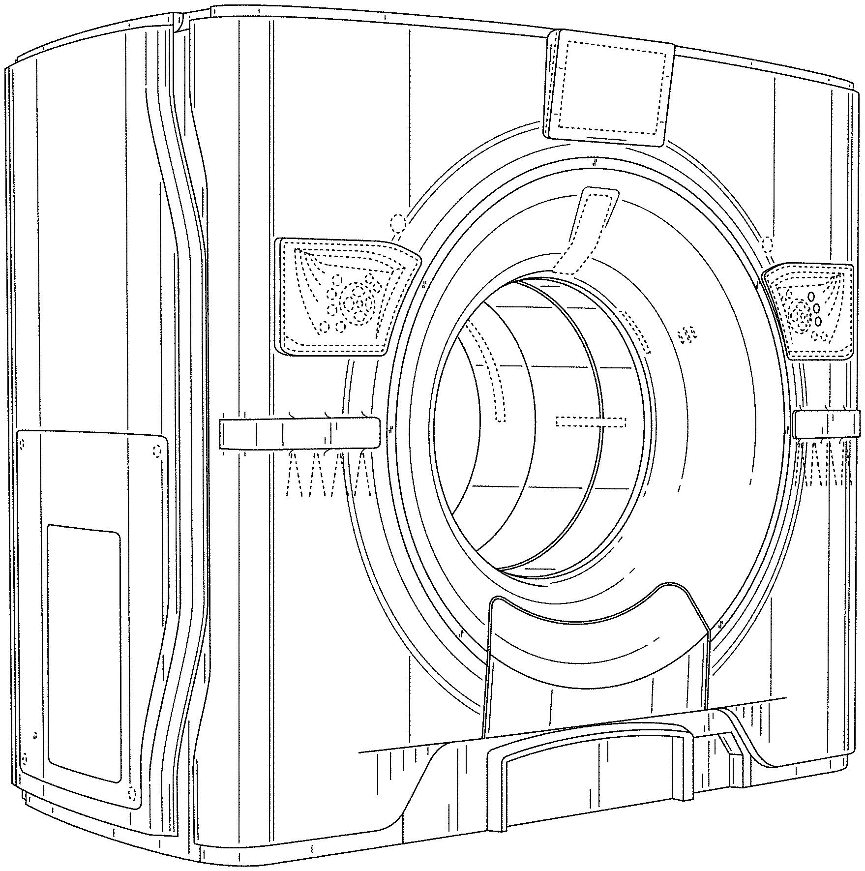
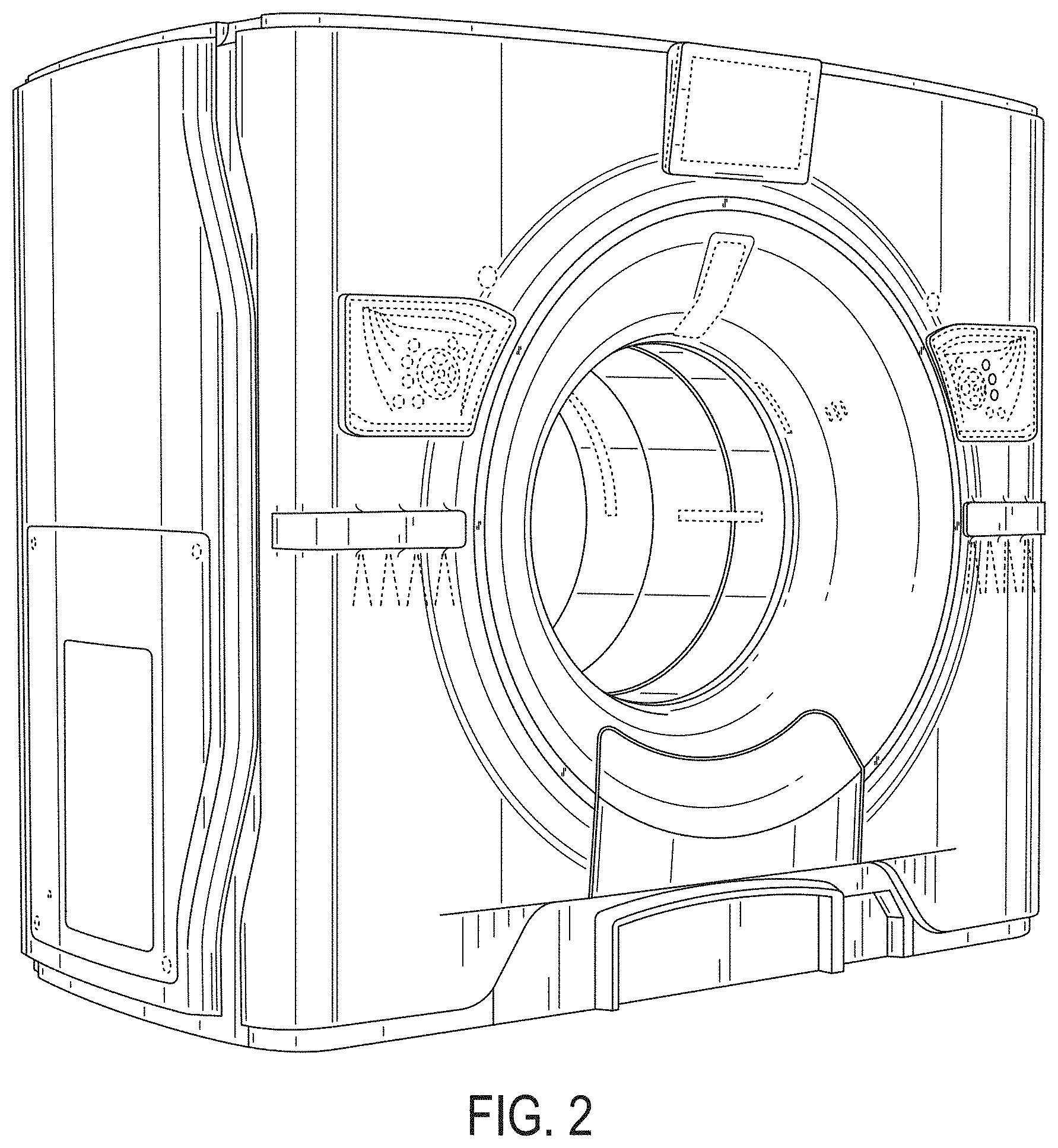
FIG. 1 is a front elevation view of a first embodiment of the imaging apparatus including accent lights.
FIG. 2 is a front-left perspective view of the imaging apparatus of FIG. 1.
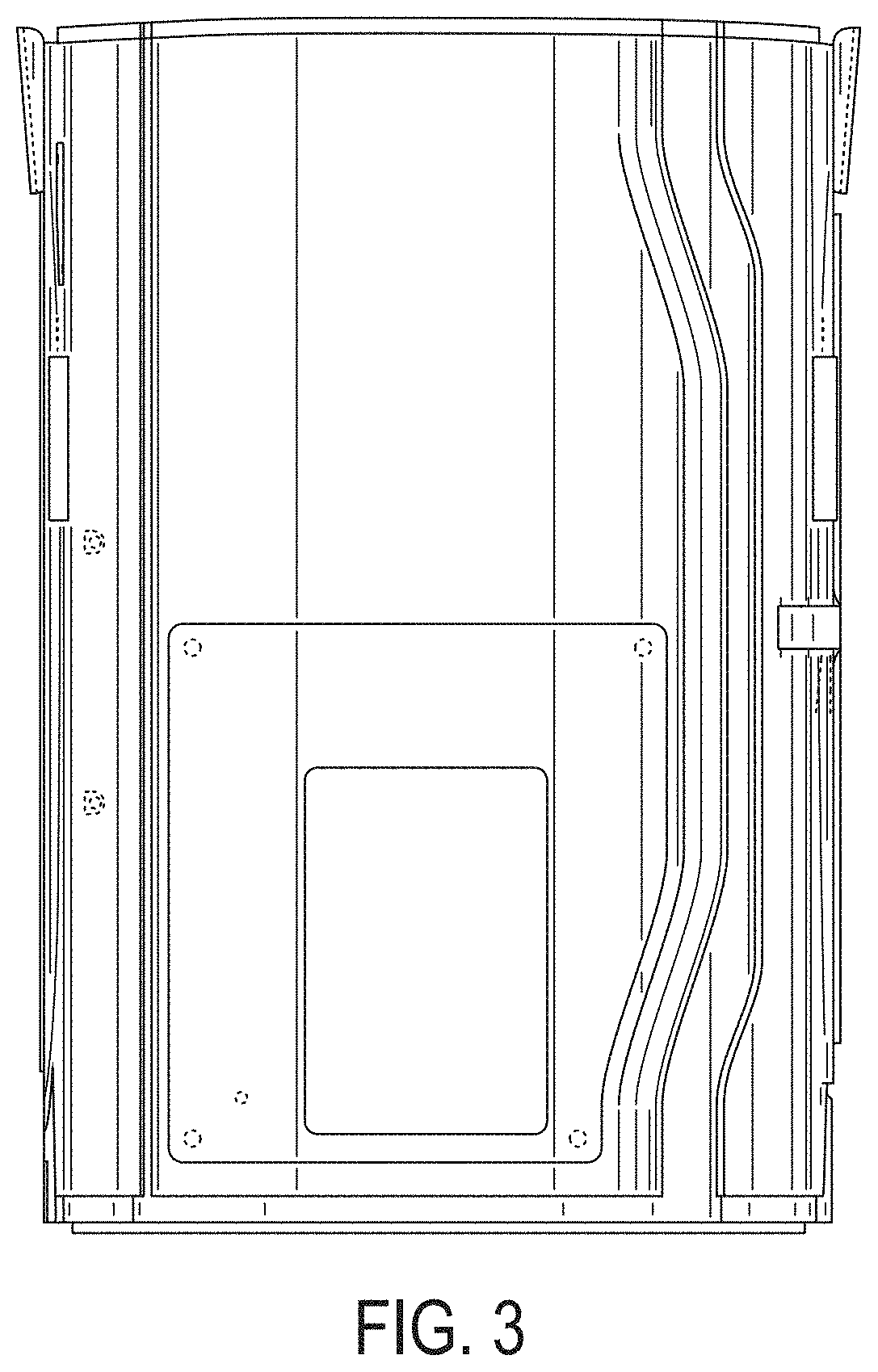
FIG. 3 is left side elevation view of the imaging apparatus of FIG. 1.
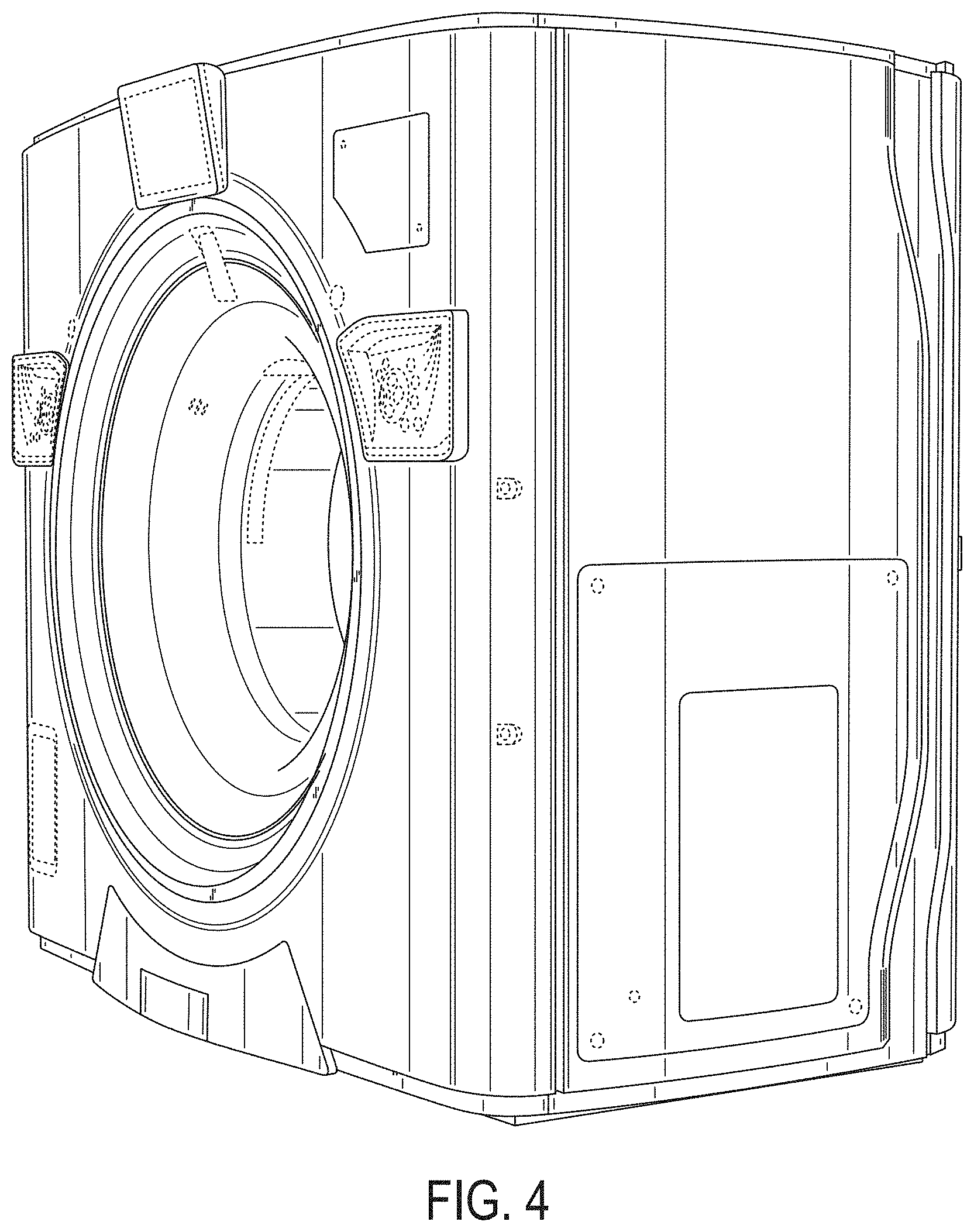
FIG. 4 is a back-left perspective view of the imaging apparatus of FIG. 1.
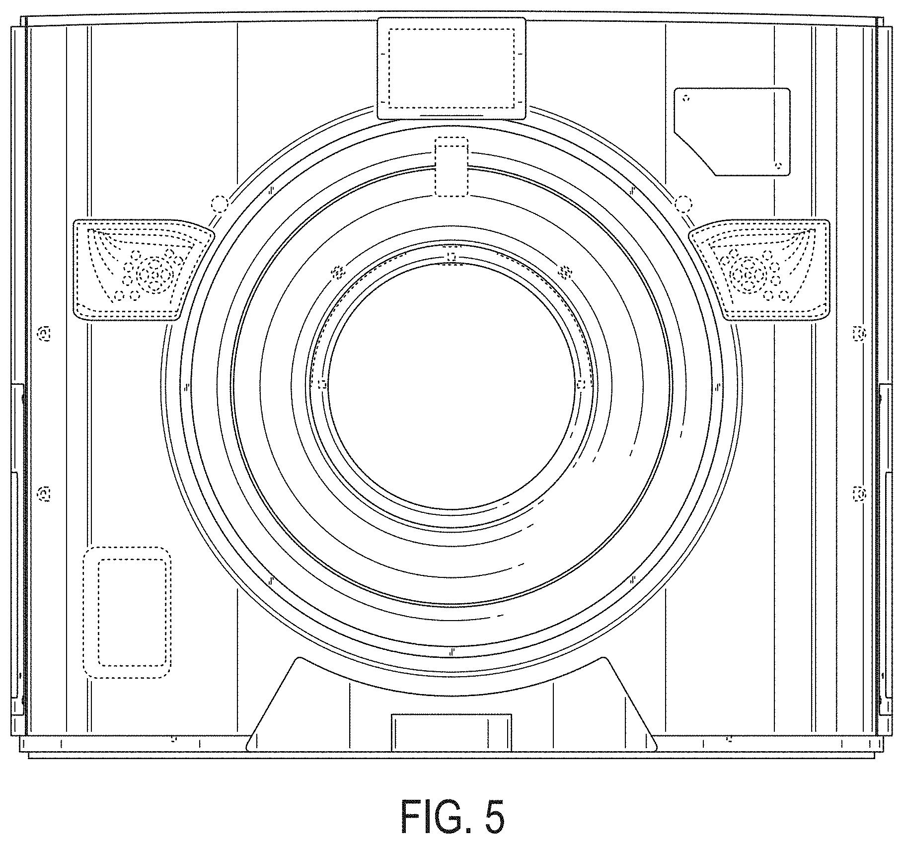
FIG. 5 is a back elevation view of the imaging apparatus of FIG. 1.
FIG. 6 is a right side elevation view of the imaging apparatus of FIG. 1.
FIG. 7 is a top plan view of the imaging apparatus of FIG. 1.
FIG. 8 is a bottom plan view of the imaging apparatus of FIG. 1.
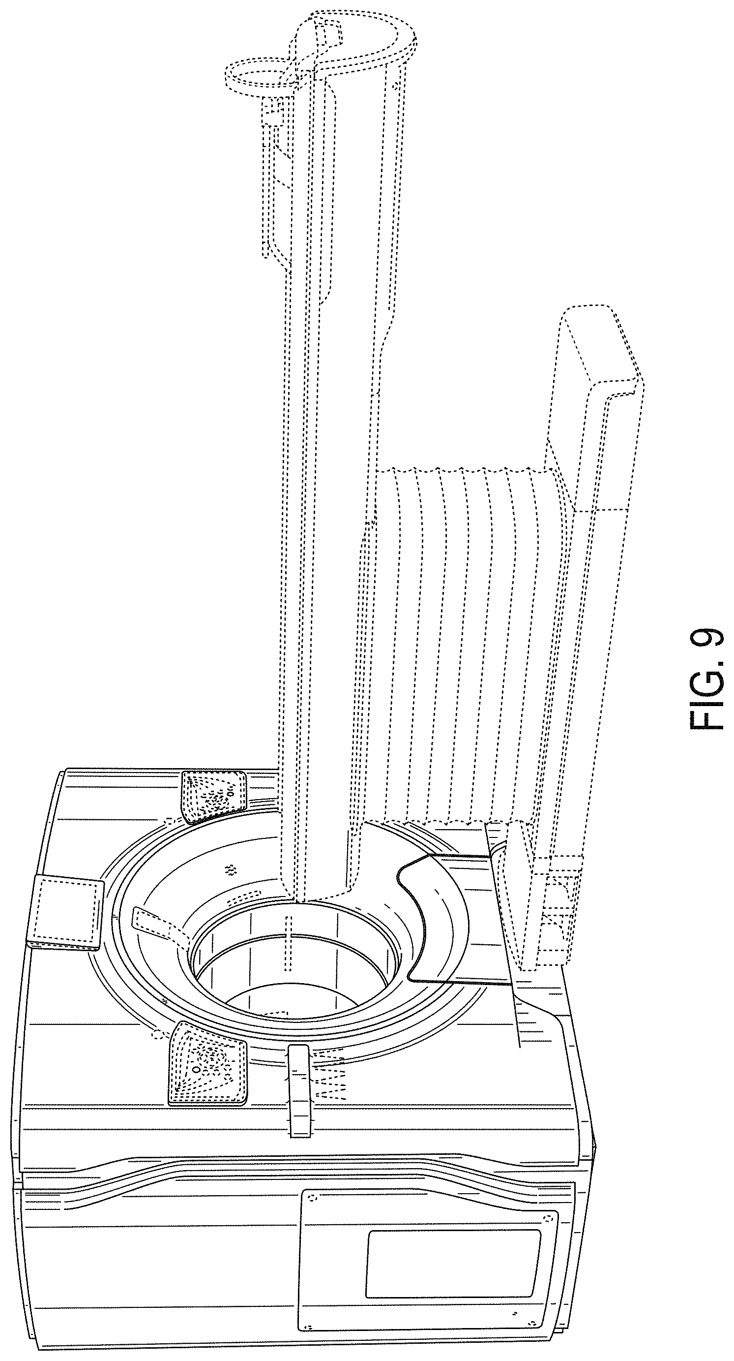
FIG. 9 is a front-left perspective view of the imaging apparatus of FIG. 1, with the patient support table shown in environment.
FIG. 10 is a front elevation view of a second embodiment of the imaging apparatus including accent lights.
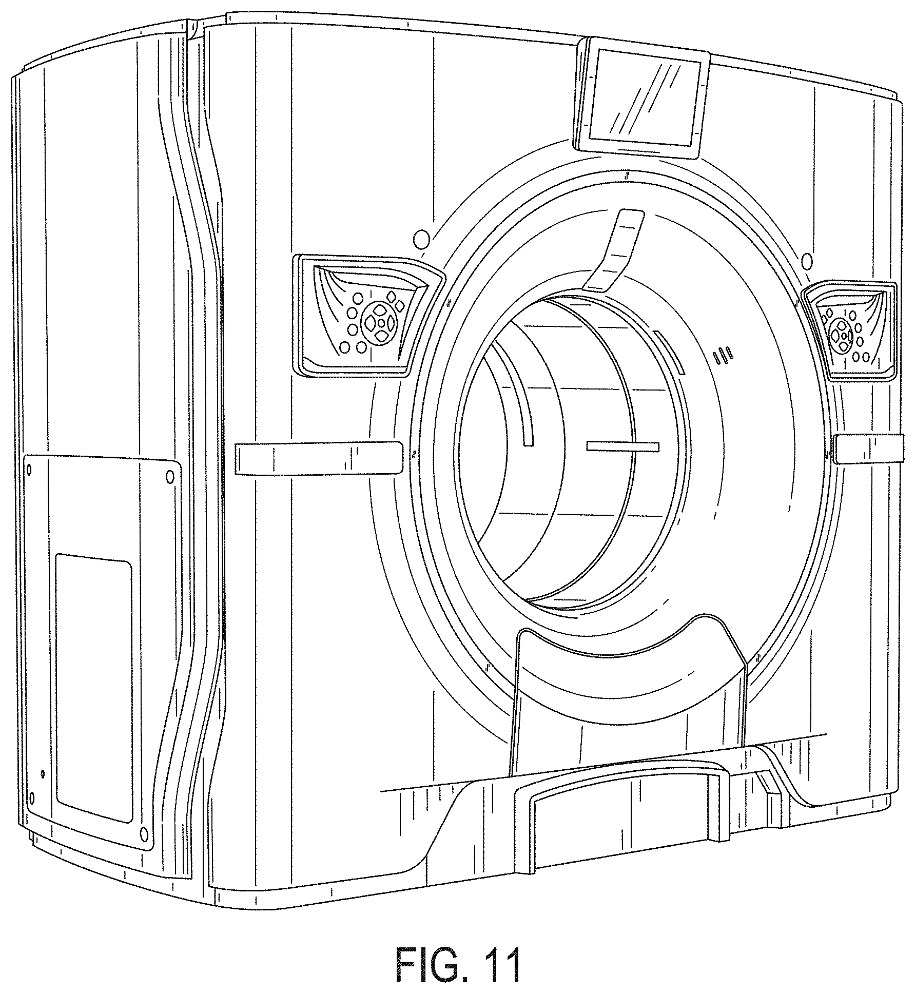
FIG. 11 is a front-left perspective view of the imaging apparatus of FIG. 10.
FIG. 12 is left side elevation view of the imaging apparatus of FIG. 10.
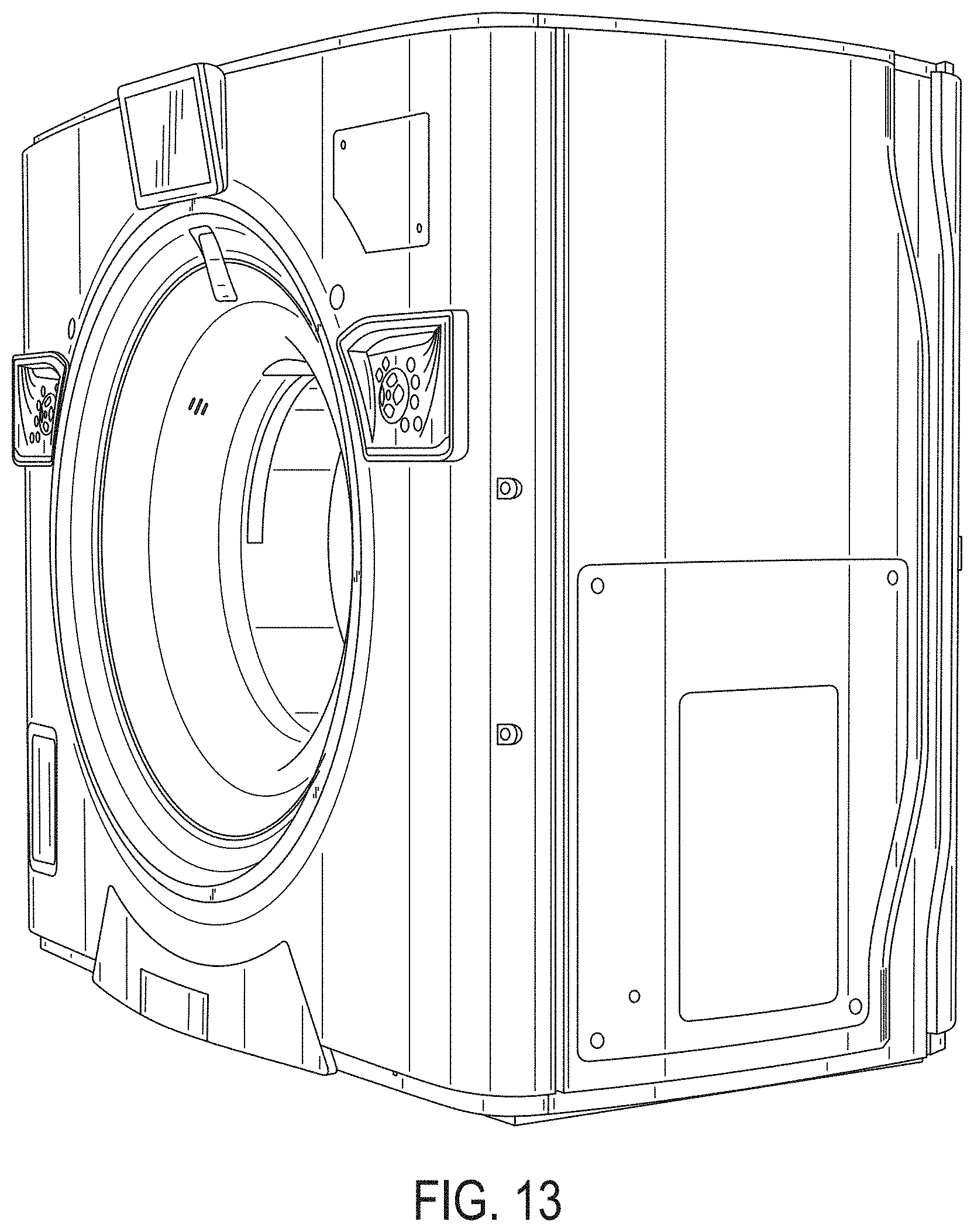
FIG. 13 is a back-left perspective view of the imaging apparatus of FIG. 10.
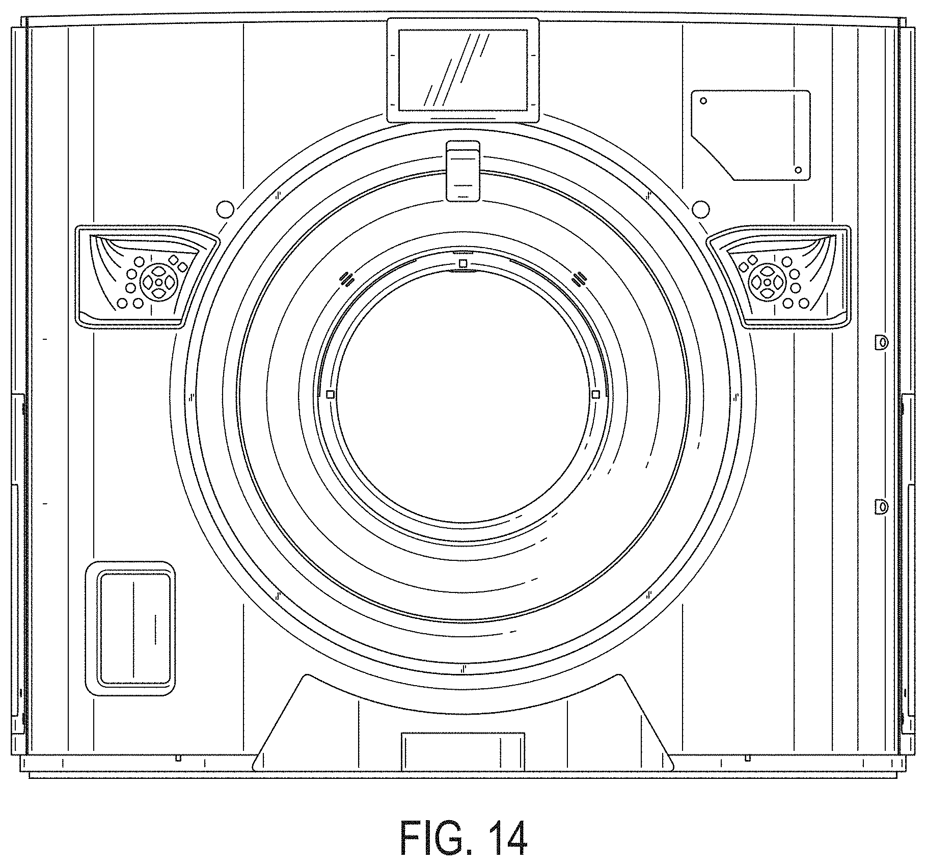
FIG. 14 is a back elevation view of the imaging apparatus of FIG. 10.
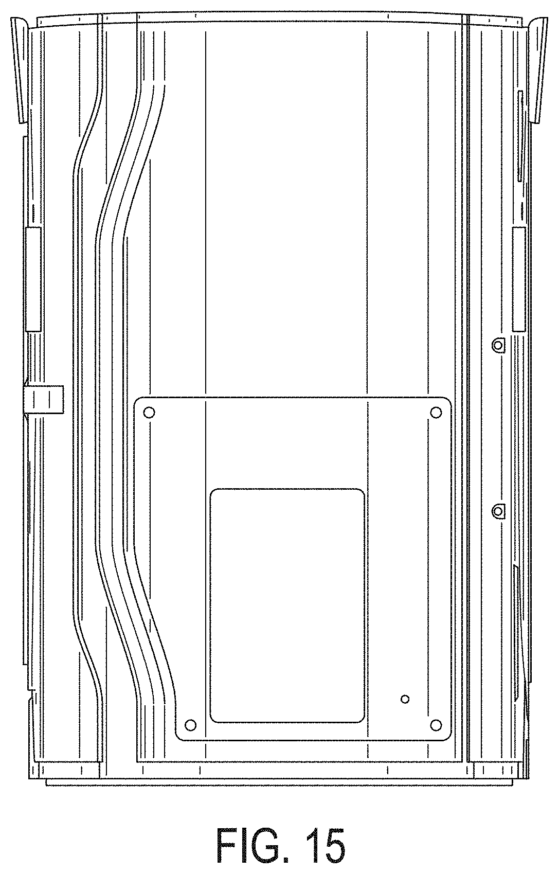
FIG. 15 is a right side elevation view of the imaging apparatus of FIG. 10.
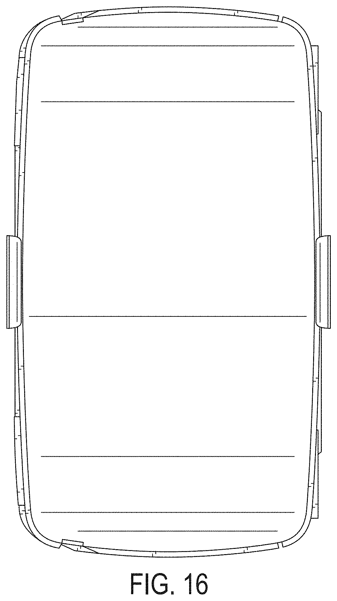
FIG. 16 is a top plan view of the imaging apparatus of FIG. 10.
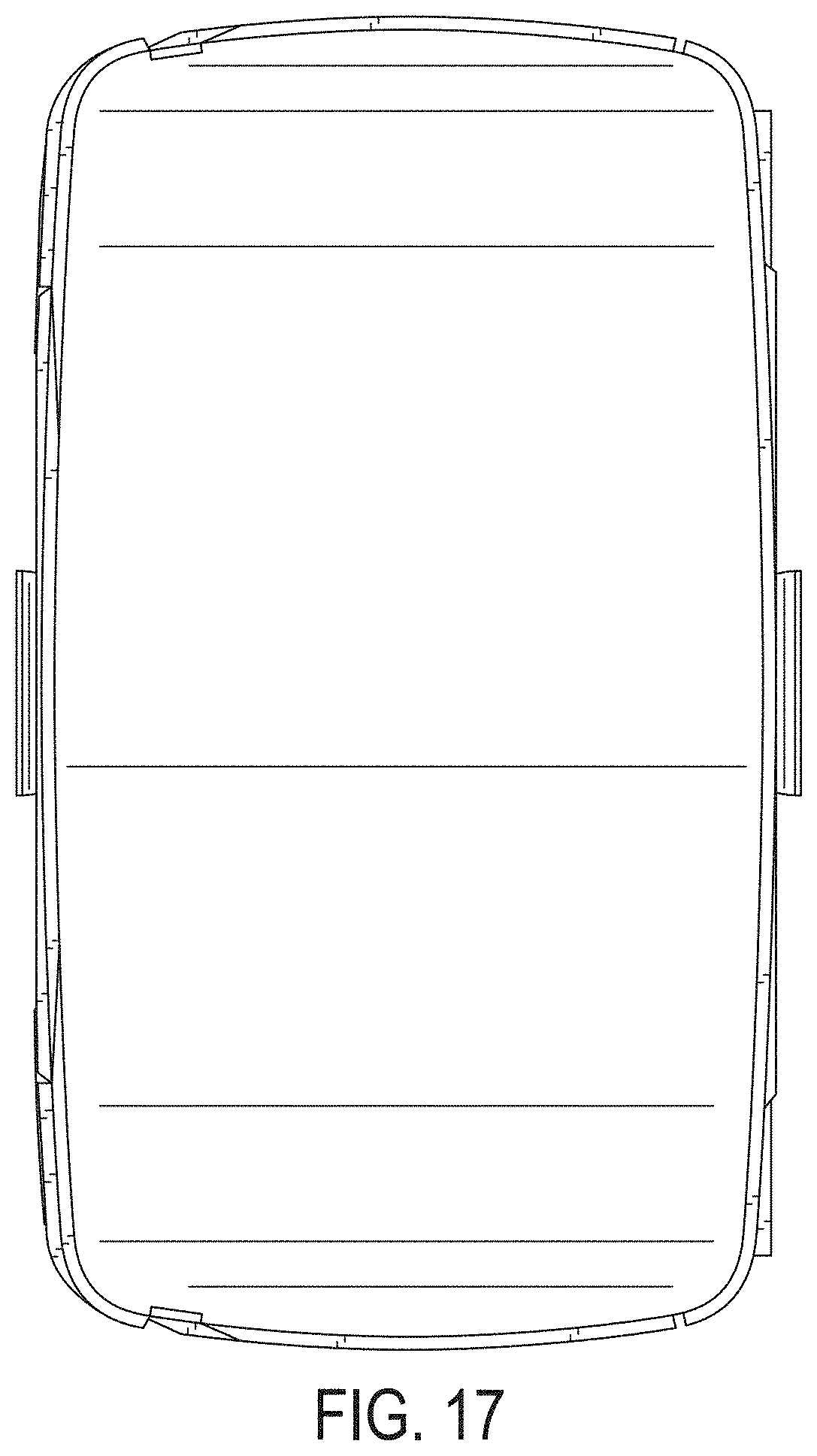
FIG. 17 is a bottom plan view of the imaging apparatus of FIG. 10; and,
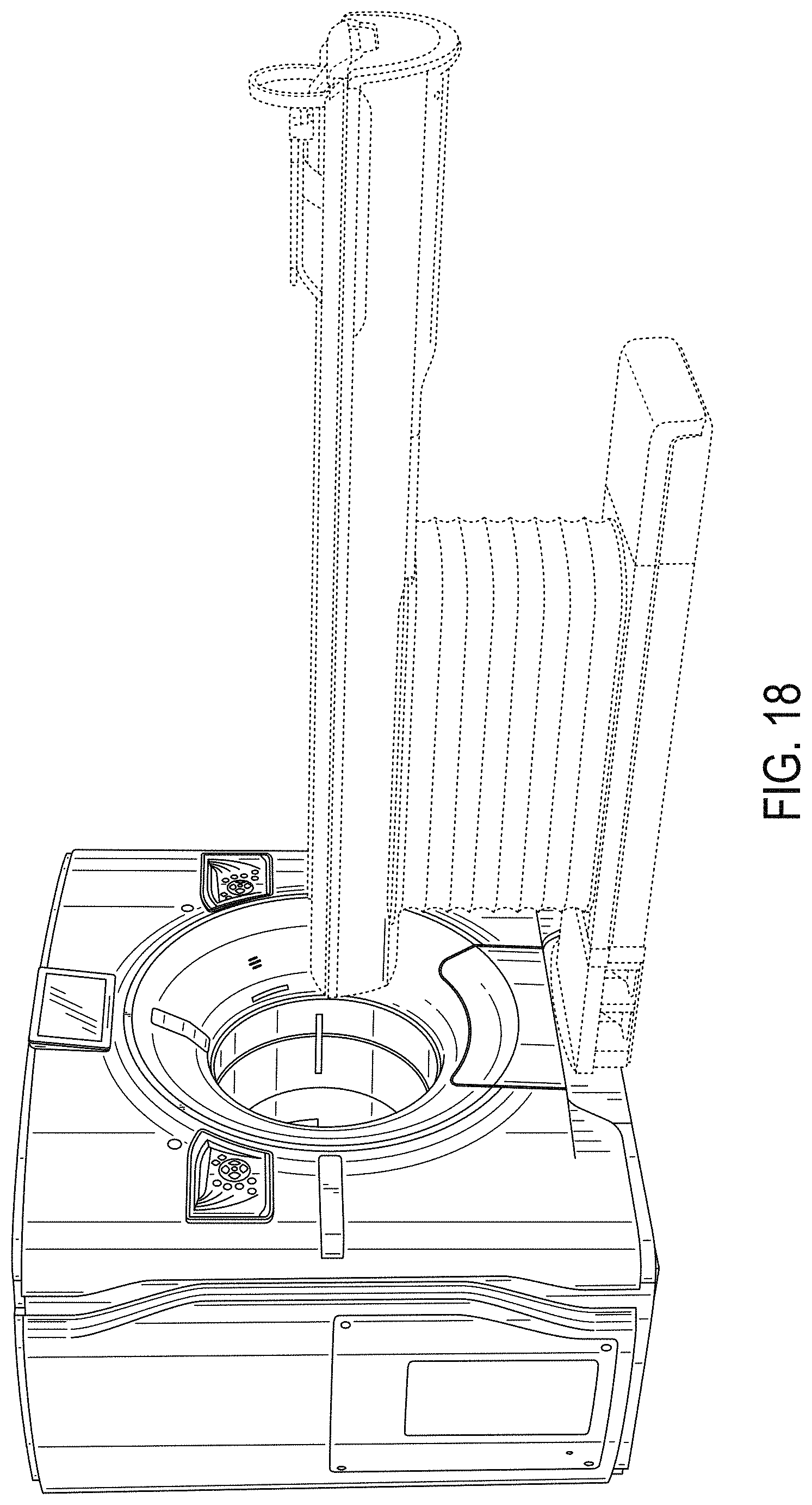
FIG. 18 is a front-left perspective view of the imaging apparatus of FIG. 10 coupled to the patient support table.
The radiating lines for the portions at the front of the imaging apparatus shown by FIGS. 1-3, 6, and 9, represent illuminated features. The broken lines in the drawing views are included for the purpose of illustrating portions of the imaging apparatus that form no part of the claimed design. For purposes of clarity, FIGS. 9 and 18 show the imaging apparatus with the patient support table. The patient support table is shown for illustrative purposes and forms no part of the claimed design.
The dash-dot-dash lines shown by FIGS. 7 and 8 indicate boundary lines enclosing portions that form no part of the claimed design.
* * * * *
D00000
D00001
D00002
D00003
D00004
D00005
D00006
D00007
D00008
D00009
D00010
D00011
D00012

D00013
D00014
D00015
D00016
D00017
D00018
XML
uspto.report is an independent third-party trademark research tool that is not affiliated, endorsed, or sponsored by the United States Patent and Trademark Office (USPTO) or any other governmental organization. The information provided by uspto.report is based on publicly available data at the time of writing and is intended for informational purposes only.
While we strive to provide accurate and up-to-date information, we do not guarantee the accuracy, completeness, reliability, or suitability of the information displayed on this site. The use of this site is at your own risk. Any reliance you place on such information is therefore strictly at your own risk.
All official trademark data, including owner information, should be verified by visiting the official USPTO website at www.uspto.gov. This site is not intended to replace professional legal advice and should not be used as a substitute for consulting with a legal professional who is knowledgeable about trademark law.