Intravaginal device assembly
Beer , et al. October 13, 2
U.S. patent number D898,911 [Application Number D/686,273] was granted by the patent office on 2020-10-13 for intravaginal device assembly. This patent grant is currently assigned to Renovia Inc.. The grantee listed for this patent is Renovia Inc.. Invention is credited to Marc D. Beer, Jose Bohorquez, Jessica L. McKinney, Samantha J. Pulliam.


| United States Patent | D898,911 |
| Beer , et al. | October 13, 2020 |
Intravaginal device assembly
Claims
CLAIM The ornamental design for an intravaginal device assembly, substantially as shown and described.
| Inventors: | Beer; Marc D. (Sudbury, MA), Bohorquez; Jose (Boston, MA), Pulliam; Samantha J. (Boston, MA), McKinney; Jessica L. (Boston, MA) | ||||||||||
|---|---|---|---|---|---|---|---|---|---|---|---|
| Applicant: |
|
||||||||||
| Assignee: | Renovia Inc. (Boston,
MA) |
||||||||||
| Appl. No.: | D/686,273 | ||||||||||
| Filed: | April 3, 2019 |
| Current U.S. Class: | D24/141 |
| Current International Class: | 2402 |
| Field of Search: | ;D24/128,135,140,121,143,152,200,214,215 ;600/29,30 ;D16/237,250 ;D28/4,76,83 ;D9/430,432 |
References Cited [Referenced By]
U.S. Patent Documents
| 2830582 | April 1958 | Ljung |
| 3854476 | December 1974 | Dickinson, III |
| 4669478 | June 1987 | Robertson |
| D310275 | August 1990 | Su |
| 5328077 | July 1994 | Lou |
| 5406961 | April 1995 | Artal |
| 5562717 | October 1996 | Tippey et al. |
| 5603685 | February 1997 | Tutrone, Jr. |
| 5674238 | October 1997 | Sample et al. |
| 5924984 | July 1999 | Rao |
| 6001060 | December 1999 | Churchill et al. |
| 6021781 | February 2000 | Thompson et al. |
| 6039701 | March 2000 | Sliwa et al. |
| 6056699 | May 2000 | Sohn et al. |
| 6086549 | July 2000 | Neese et al. |
| 6264582 | July 2001 | Remes |
| 6272371 | August 2001 | Shlomo |
| 6511427 | January 2003 | Sliwa, Jr. et al. |
| 6672996 | January 2004 | Ross et al. |
| 6679854 | January 2004 | Honda et al. |
| 6816744 | November 2004 | Garfield et al. |
| 7079882 | July 2006 | Schmidt |
| 7577476 | August 2009 | Hochman et al. |
| 7608037 | October 2009 | Levy |
| 7628744 | December 2009 | Hoffman et al. |
| 7645220 | January 2010 | Hoffman et al. |
| 7837682 | November 2010 | Ostrovsky et al. |
| 7955241 | June 2011 | Hoffman et al. |
| 7957794 | June 2011 | Hochman et al. |
| 8147429 | April 2012 | Mittal et al. |
| 8360954 | January 2013 | Kim |
| 8623004 | January 2014 | Johnson et al. |
| 8715204 | May 2014 | Webster et al. |
| 8728140 | May 2014 | Feemster et al. |
| 8805472 | August 2014 | Iglesias |
| 8821407 | September 2014 | Kirsner |
| 8914111 | December 2014 | Haessler |
| 8983627 | March 2015 | Pelger et al. |
| 9155885 | October 2015 | Wei et al. |
| 9248285 | February 2016 | Haessler |
| 9381351 | July 2016 | Haessler |
| 9408685 | August 2016 | Hou |
| 9656067 | May 2017 | Pelger et al. |
| 9861316 | January 2018 | Egorov |
| D853035 | July 2019 | Moretti |
| 2001/0047132 | November 2001 | Johnson et al. |
| 2002/0111586 | August 2002 | Mosel et al. |
| 2003/0028180 | February 2003 | Franco |
| 2004/0236223 | November 2004 | Barnes et al. |
| 2004/0260207 | December 2004 | Eini et al. |
| 2005/0148447 | July 2005 | Nady |
| 2006/0036188 | February 2006 | Hoffman et al. |
| 2006/0074289 | April 2006 | Adler et al. |
| 2006/0084848 | April 2006 | Mitchnick |
| 2007/0066880 | March 2007 | Lee et al. |
| 2007/0232882 | October 2007 | Glossop et al. |
| 2007/0255090 | November 2007 | Addington et al. |
| 2007/0265675 | November 2007 | Lund et al. |
| 2007/0270686 | November 2007 | Ritter et al. |
| 2008/0077053 | March 2008 | Epstein et al. |
| 2008/0139876 | June 2008 | Kim |
| 2008/0146941 | June 2008 | Dala-Krishna |
| 2008/0149109 | June 2008 | Ziv |
| 2008/0154131 | June 2008 | Lee et al. |
| 2008/0171950 | July 2008 | Franco |
| 2009/0149740 | June 2009 | Hoheisel |
| 2009/0270963 | October 2009 | Pelger et al. |
| 2009/0306509 | December 2009 | Pedersen et al. |
| 2010/0174218 | July 2010 | Shim |
| 2010/0249576 | September 2010 | Askarinya et al. |
| 2010/0262049 | October 2010 | Novak et al. |
| 2011/0054357 | March 2011 | Egorov et al. |
| 2011/0077500 | March 2011 | Shakiba |
| 2011/0190580 | August 2011 | Bennett et al. |
| 2011/0190595 | August 2011 | Bennett et al. |
| 2011/0196263 | August 2011 | Egorov et al. |
| 2012/0016258 | January 2012 | Webster et al. |
| 2012/0265044 | October 2012 | Broens |
| 2012/0265049 | October 2012 | Iglesias |
| 2013/0035611 | February 2013 | White |
| 2013/0053627 | February 2013 | Bercovich et al. |
| 2013/0144191 | June 2013 | Egorov et al. |
| 2013/0184567 | July 2013 | Xie et al. |
| 2013/0192606 | August 2013 | Ziv et al. |
| 2013/0237771 | September 2013 | Runkewitz et al. |
| 2013/0324380 | December 2013 | Horsley |
| 2014/0066813 | March 2014 | Daly |
| 2014/0073879 | March 2014 | Cantor et al. |
| 2014/0088471 | March 2014 | Leivseth et al. |
| 2014/0155225 | June 2014 | Sedic |
| 2014/0213927 | July 2014 | Webster et al. |
| 2014/0296705 | October 2014 | Iglesias |
| 2014/0309550 | October 2014 | Iglesias |
| 2015/0032030 | January 2015 | Iglesias |
| 2015/0112230 | April 2015 | Iglesias |
| 2015/0112231 | April 2015 | Iglesias |
| 2015/0133832 | May 2015 | Courtion et al. |
| 2015/0196802 | July 2015 | Siegel |
| 2015/0282763 | October 2015 | Rosenshein |
| 2016/0008664 | January 2016 | Siegel |
| 2016/0074276 | March 2016 | Scheuring et al. |
| 2016/0121105 | May 2016 | Lee et al. |
| 2016/0346610 | December 2016 | Iglesias et al. |
| 2017/0281072 | October 2017 | Iglesias |
| 2017/0281299 | October 2017 | Iglesias |
| 2017/0291012 | October 2017 | Iglesias |
| 2017/0303843 | October 2017 | Iglesias |
| 2017/0332959 | November 2017 | Bartlett |
| 2019/0160332 | May 2019 | Beer et al. |
| 2625428 | Jul 2007 | CA | |||
| 204839545 | Dec 2015 | CN | |||
| 10345282 | Apr 2005 | DE | |||
| 202018103016 | Jun 2018 | DE | |||
| 0268972 | Jun 1988 | EP | |||
| 2689724 | Jan 2014 | EP | |||
| 2492754 | Jan 2013 | GB | |||
| 2009-538176 | Nov 2009 | JP | |||
| 2011-183167 | Sep 2011 | JP | |||
| WO-96/05768 | Feb 1996 | WO | |||
| WO-99/05963 | Feb 1999 | WO | |||
| WO-00/09013 | Feb 2000 | WO | |||
| WO-00/23030 | Apr 2000 | WO | |||
| WO-01/37732 | May 2001 | WO | |||
| WO-2006/107930 | Oct 2006 | WO | |||
| WO-2007/136266 | Nov 2007 | WO | |||
| WO-2010/131252 | Nov 2010 | WO | |||
| WO-2011/050252 | Apr 2011 | WO | |||
| WO-2011/121591 | Oct 2011 | WO | |||
| WO-2011/159906 | Dec 2011 | WO | |||
| WO-2012/079127 | Jun 2012 | WO | |||
| WO-2012/138232 | Oct 2012 | WO | |||
| WO-2013/082006 | Jun 2013 | WO | |||
| WO-2013/116310 | Aug 2013 | WO | |||
| WO-2015/103629 | Jul 2015 | WO | |||
| WO-2016/026914 | Feb 2016 | WO | |||
| WO-2016/042310 | Mar 2016 | WO | |||
| WO-2016/067023 | May 2016 | WO | |||
| WO-2018/023037 | Feb 2018 | WO | |||
| WO-2019/084468 | May 2019 | WO | |||
| WO-2019/084469 | May 2019 | WO | |||
Other References
|
Rosenblatt et al., "Evaluation of an accelerometer-based digital health system for the treatment of female urinary incontinence: A pilot study," Neurourol Urodyn. 38(7): 1944-1952 (2019). cited by applicant . Rosenblatt et al., "Interactive Pelvic Floor Muscle Training for Female Urinary Incontinence," Renovia, Inc., retrieved Apr. 30, 2019 from <https://renoviainc.com/wp-content/uploads/2018/04/REN005.01-White-Pap- er-12Apr18-FINAL.pdf> (2018) (6 pages). cited by applicant. |
Primary Examiner: Laymon; Wan
Assistant Examiner: Samuel; Clint A
Attorney, Agent or Firm: Clark & Elbing LLP
Description
FIG. 1 is a front and left side perspective view of an intravaginal device assembly, with the intravaginal device removed from the case for ease of illustration, embodying the claimed design.
FIG. 2 is an enlarged front view of the intravaginal device of FIG. 1.
FIG. 3 is an enlarged rear view of the intravaginal device of FIG. 1.
FIG. 4 is a top view of the intravaginal device of FIG. 1.
FIG. 5 is a bottom view of the intravaginal device of FIG. 1.
FIG. 6 is a right side view of the intravaginal device of FIG. 1.
FIG. 7 is a left side view of the intravaginal device of FIG. 1.
FIG. 8 is a front and left side perspective view of a case, in the closed position, containing the intravaginal device shown in FIG. 1.
FIG. 9 is an exploded view of the case and intravaginal device of FIG. 8.
FIG. 10 is a front and left side perspective view of a partially opened case containing the intravaginal device shown in FIG. 1.
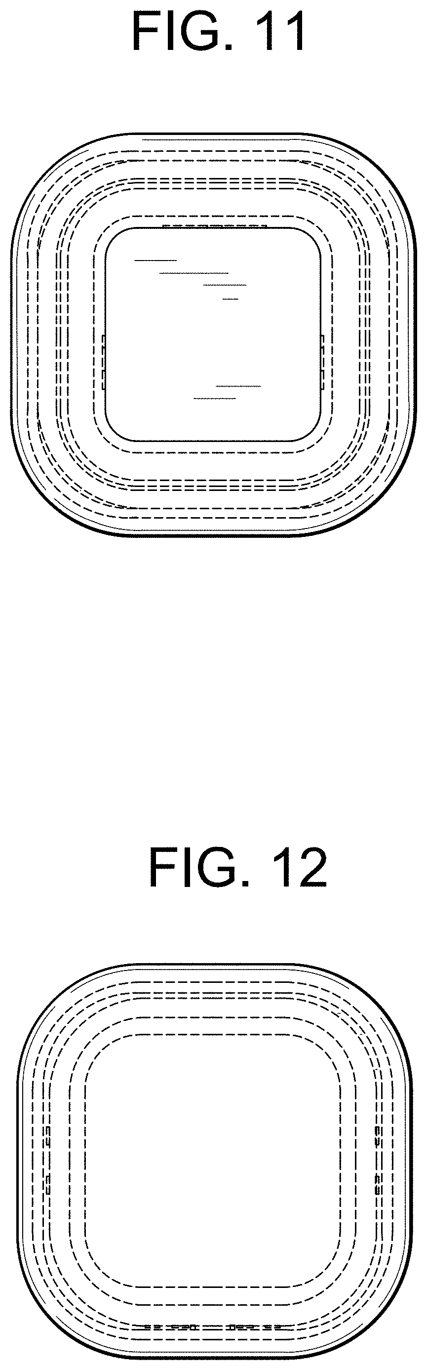
FIG. 11 is an enlarged front view of the case containing the intravaginal device shown in FIG. 8.
FIG. 12 is an enlarged rear view of the case containing the intravaginal device shown in FIG. 8.
FIG. 13 is a right side view of the case and intravaginal device shown in FIG. 10.
FIG. 14 is a left side view of the case and intravaginal device shown in FIG. 10.
FIG. 15 is a top view of the case and intravaginal device shown in FIG. 10; and,
FIG. 16 is a bottom view of the case and intravaginal device shown in FIG. 10.
The broken lines show portions of the intravaginal device assembly that form no part of the claimed design.
* * * * *
References
D00000
D00001
D00002
D00003
D00004
D00005
D00006
D00007
D00008
D00009
D00010
XML
uspto.report is an independent third-party trademark research tool that is not affiliated, endorsed, or sponsored by the United States Patent and Trademark Office (USPTO) or any other governmental organization. The information provided by uspto.report is based on publicly available data at the time of writing and is intended for informational purposes only.
While we strive to provide accurate and up-to-date information, we do not guarantee the accuracy, completeness, reliability, or suitability of the information displayed on this site. The use of this site is at your own risk. Any reliance you place on such information is therefore strictly at your own risk.
All official trademark data, including owner information, should be verified by visiting the official USPTO website at www.uspto.gov. This site is not intended to replace professional legal advice and should not be used as a substitute for consulting with a legal professional who is knowledgeable about trademark law.