Power adapter with retracting cord
Ebrahimi Afrouzi , et al. Sept
U.S. patent number D896,751 [Application Number D/627,470] was granted by the patent office on 2020-09-22 for power adapter with retracting cord. The grantee listed for this patent is Ali Ebrahimi Afrouzi, Shahin Fathi Djalali. Invention is credited to Ali Ebrahimi Afrouzi, Shahin Fathi Djalali.


| United States Patent | D896,751 |
| Ebrahimi Afrouzi , et al. | September 22, 2020 |
Power adapter with retracting cord
Claims
CLAIM The ornamental design for a power adapter with retracting cord, as shown and described.
| Inventors: | Ebrahimi Afrouzi; Ali (San Jose, CA), Fathi Djalali; Shahin (San Francisco, CA) | ||||||||||
|---|---|---|---|---|---|---|---|---|---|---|---|
| Applicant: |
|
||||||||||
| Appl. No.: | D/627,470 | ||||||||||
| Filed: | November 28, 2017 |
| Current U.S. Class: | D13/110; D14/433 |
| Current International Class: | 1302 |
| Field of Search: | ;D13/110,103,107,108,118,119,138.1,138.2,139.1,139.2,184,199 ;D14/253,432,433,434 ;320/107-115 ;439/103,104,105,131,172 |
References Cited [Referenced By]
U.S. Patent Documents
| D645818 | September 2011 | Guccione |
| D678285 | March 2013 | Chen |
| D735131 | July 2015 | Akana |
| D796435 | September 2017 | Cho |
| D798807 | October 2017 | Shi |
| D821309 | June 2018 | Barnard |
| 2016/0043584 | February 2016 | Sun |
| 2016/0276856 | September 2016 | Miller |
Description
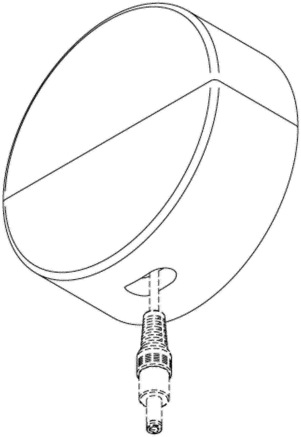
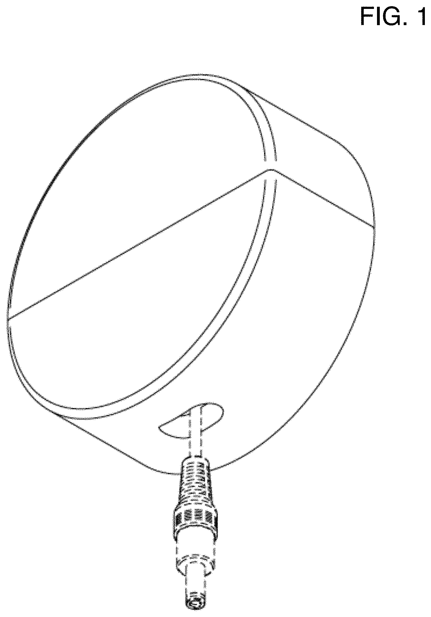
FIG. 1 is a first perspective view of a power adapter with retracting cord showing our new design;
FIG. 2 is a second perspective view thereof;
FIG. 3 is a front elevation view thereof, shown with a circular indicator;
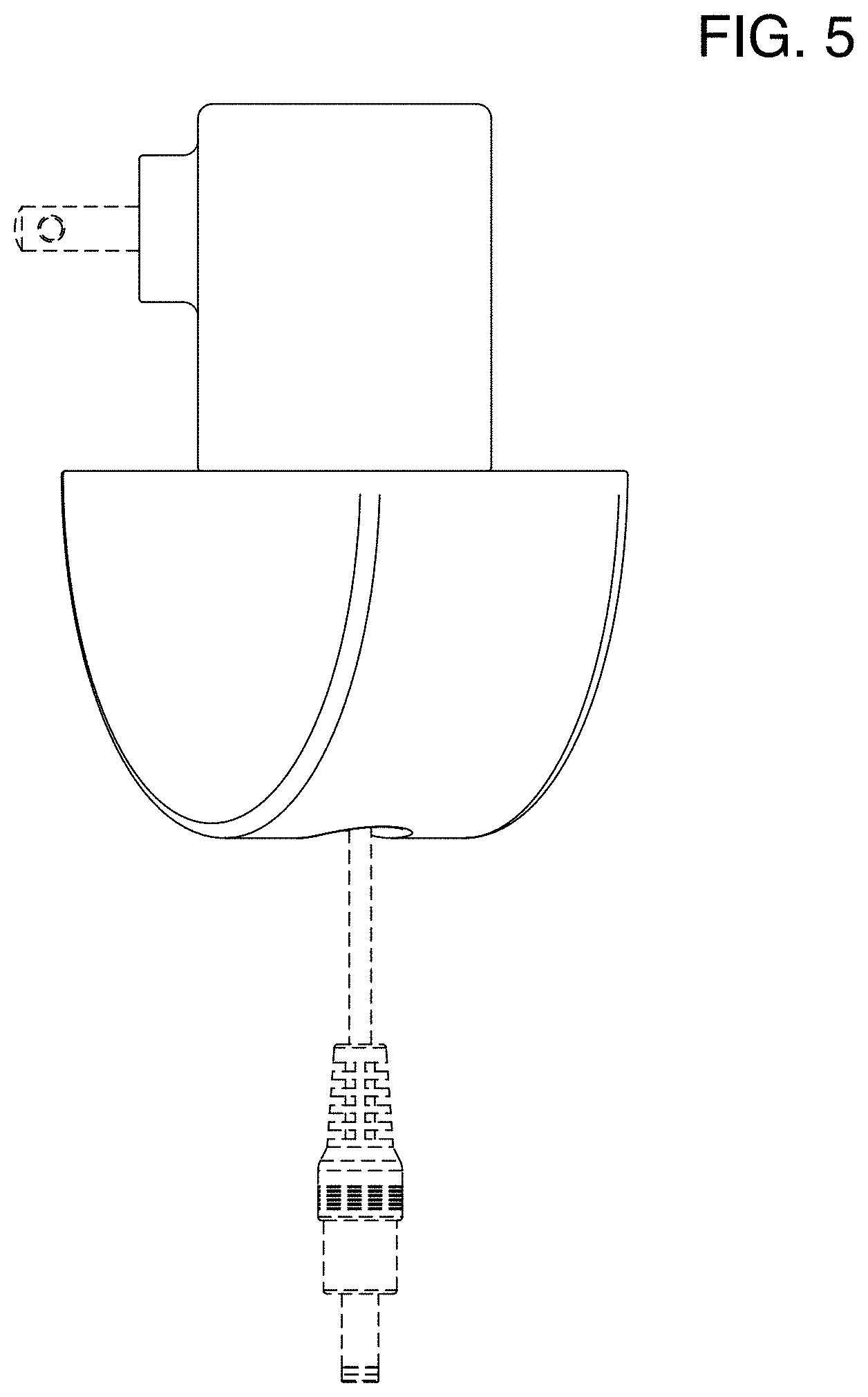
FIG. 4 is a front elevation view thereof, shown in an alternate position;
FIG. 5 is a left side elevation view of that shown in FIG. 4;
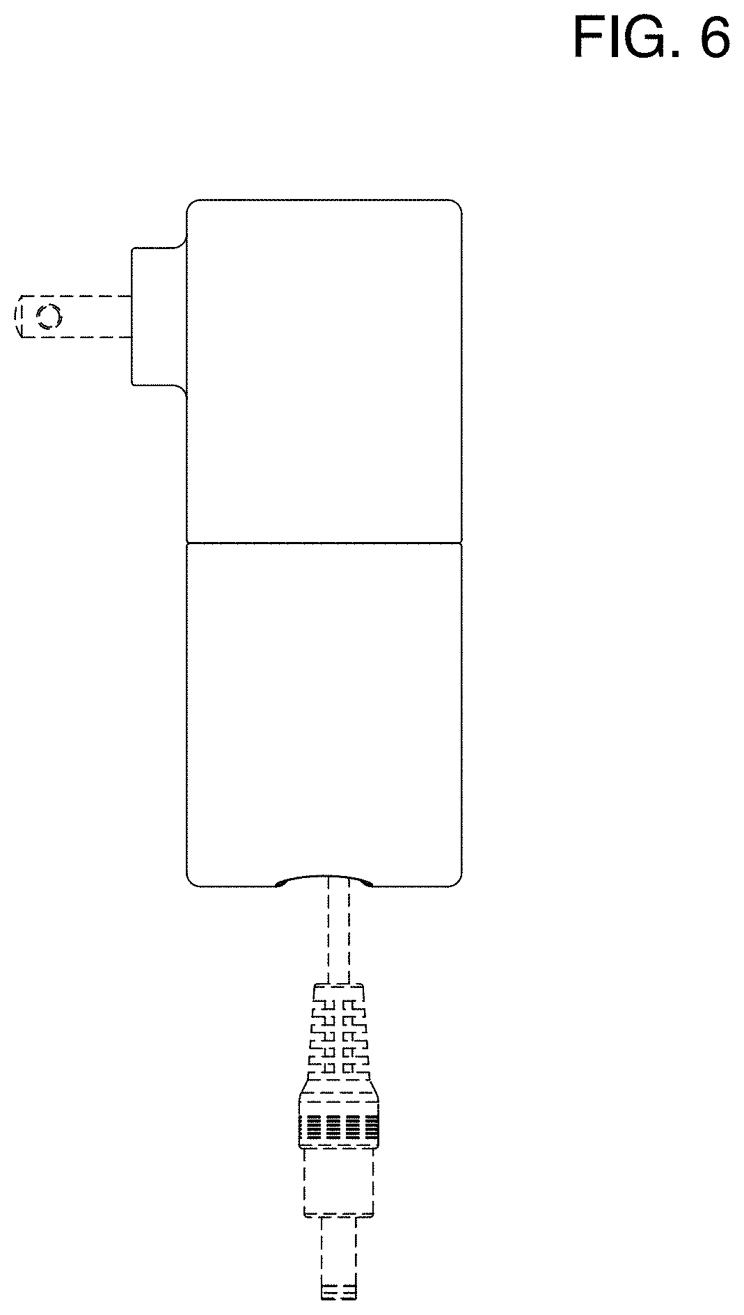
FIG. 6 is a left side elevation view of that shown in FIGS. 1 and 3;
FIG. 7 is a bottom plan view of that shown in FIG. 4;
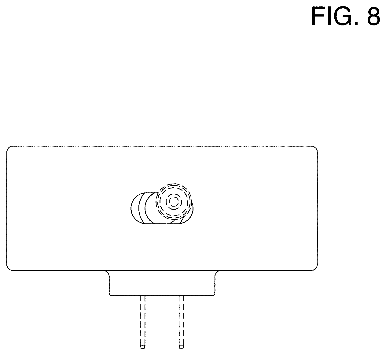
FIG. 8 is bottom plan view of that shown in FIGS. 1 and 3;
FIG. 9 is a top plan view of that shown in FIG. 4; and,
FIG. 10 is a top plan view of that shown in FIGS. 1 and 3.
The broken lines illustrate the portions of the power adapter with retracting cord that form no part of the claimed design.
* * * * *
D00000
D00001
D00002
D00003
D00004
D00005
D00006
D00007
D00008
D00009
D00010
XML
uspto.report is an independent third-party trademark research tool that is not affiliated, endorsed, or sponsored by the United States Patent and Trademark Office (USPTO) or any other governmental organization. The information provided by uspto.report is based on publicly available data at the time of writing and is intended for informational purposes only.
While we strive to provide accurate and up-to-date information, we do not guarantee the accuracy, completeness, reliability, or suitability of the information displayed on this site. The use of this site is at your own risk. Any reliance you place on such information is therefore strictly at your own risk.
All official trademark data, including owner information, should be verified by visiting the official USPTO website at www.uspto.gov. This site is not intended to replace professional legal advice and should not be used as a substitute for consulting with a legal professional who is knowledgeable about trademark law.