Rail for a conveyor system
Kleinikkink , et al. Sep
U.S. patent number D895,922 [Application Number D/649,188] was granted by the patent office on 2020-09-08 for rail for a conveyor system. This patent grant is currently assigned to ATS AUTOMATION TOOLING SYSTEMS INC.. The grantee listed for this patent is ATS AUTOMATION TOOLING SYSTEMS INC.. Invention is credited to Ian Cameron, Roger Hogan, Albert Kleinikkink.


View All Diagrams
| United States Patent | D895,922 |
| Kleinikkink , et al. | September 8, 2020 |
Rail for a conveyor system
Claims
CLAIM The ornamental design for a rail for a conveyor system, as shown and described.
| Inventors: | Kleinikkink; Albert (Cambridge, CA), Cameron; Ian (Cambridge, CA), Hogan; Roger (Cambridge, CA) | ||||||||||
|---|---|---|---|---|---|---|---|---|---|---|---|
| Applicant: |
|
||||||||||
| Assignee: | ATS AUTOMATION TOOLING SYSTEMS
INC. (Cambridge, Ontario, CA) |
||||||||||
| Appl. No.: | D/649,188 | ||||||||||
| Filed: | May 28, 2018 |
Related U.S. Patent Documents
| Application Number | Filing Date | Patent Number | Issue Date | ||
|---|---|---|---|---|---|
| 29627542 | Nov 28, 2017 | ||||
| Current U.S. Class: | D34/29; D34/35 |
| Current International Class: | 1205 |
| Field of Search: | ;D34/29,35 ;D25/119 |
References Cited [Referenced By]
U.S. Patent Documents
| 1796316 | March 1931 | Bemis |
| 3131792 | May 1964 | Groneman |
| D238510 | January 1976 | Tabler |
| 4811516 | March 1989 | Anderson |
| D322255 | December 1991 | Prados |
| D350612 | September 1994 | Gullblom |
| D464783 | October 2002 | Abbestam |
| D547884 | July 2007 | Aughton |
| D561421 | February 2008 | Cheng |
| D565271 | March 2008 | Falbaum |
| D584473 | January 2009 | Campbell |
| D587731 | March 2009 | Niedermeyer |
| D643545 | August 2011 | McDonald |
| D660544 | May 2012 | Onayama |
| D670474 | November 2012 | Koch |
| D701015 | March 2014 | Specht |
| D726988 | April 2015 | Baric |
| D729487 | May 2015 | Dockx |
| D737536 | August 2015 | Baek |
| D764140 | August 2016 | Holzhaeuser |
| D771277 | November 2016 | McCue |
| D828673 | September 2018 | Vroom |
| D834729 | November 2018 | Lee |
| 2018/0273301 | September 2018 | Breton |
Attorney, Agent or Firm: Gowling WLG (Canada) LLP Henderson; Neil W.
Description
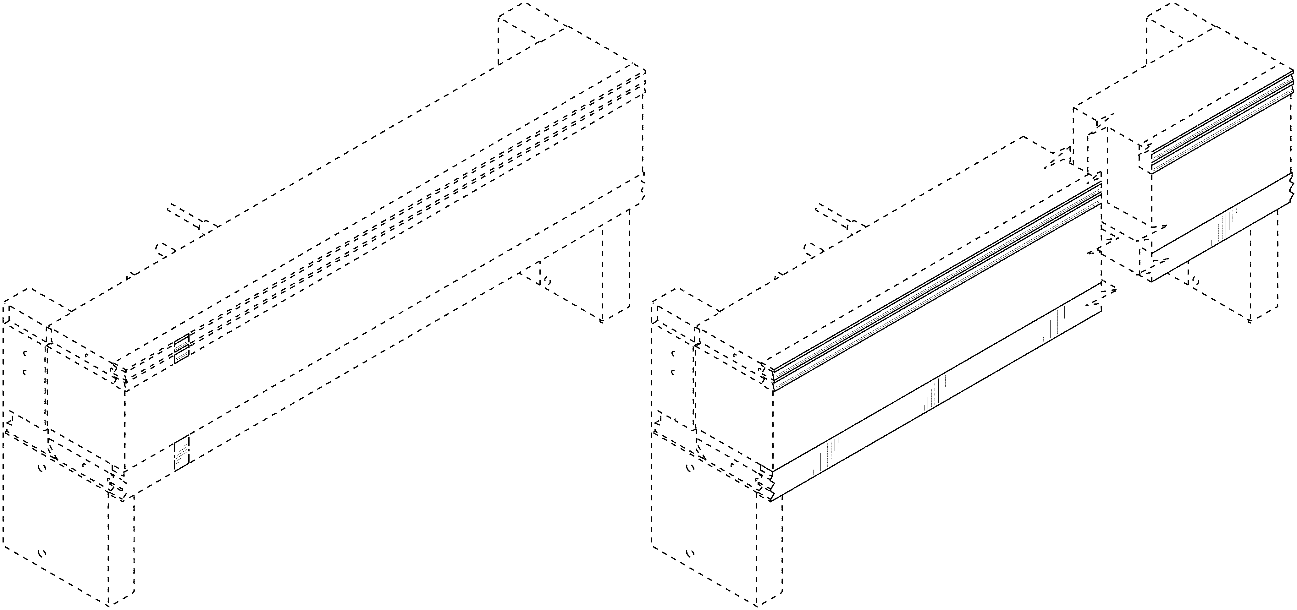
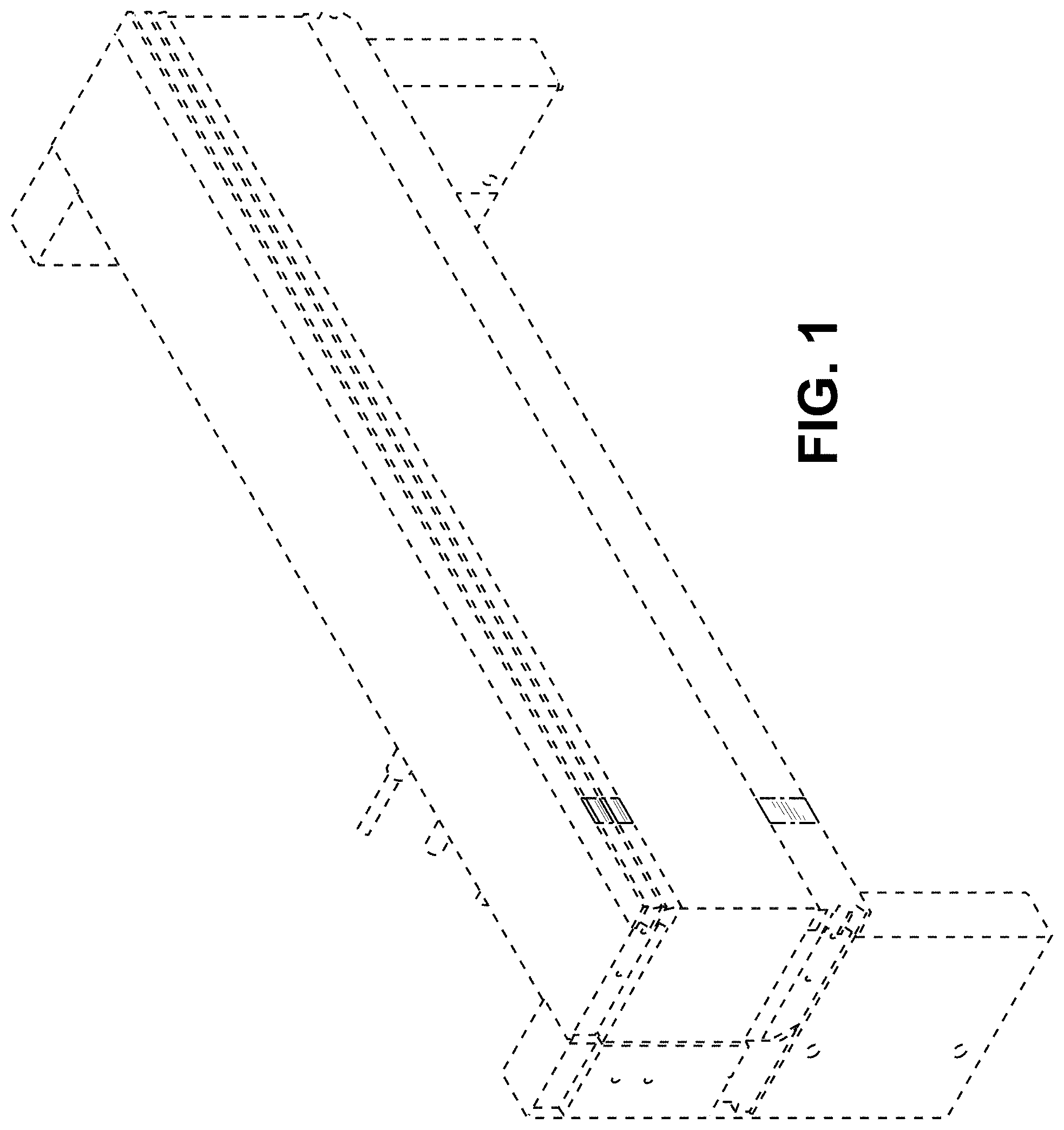
FIG. 1 is a front top left perspective view of a rail for a conveyor system showing our new design according to an embodiment.
FIG. 2 is a rear bottom right perspective view thereof.
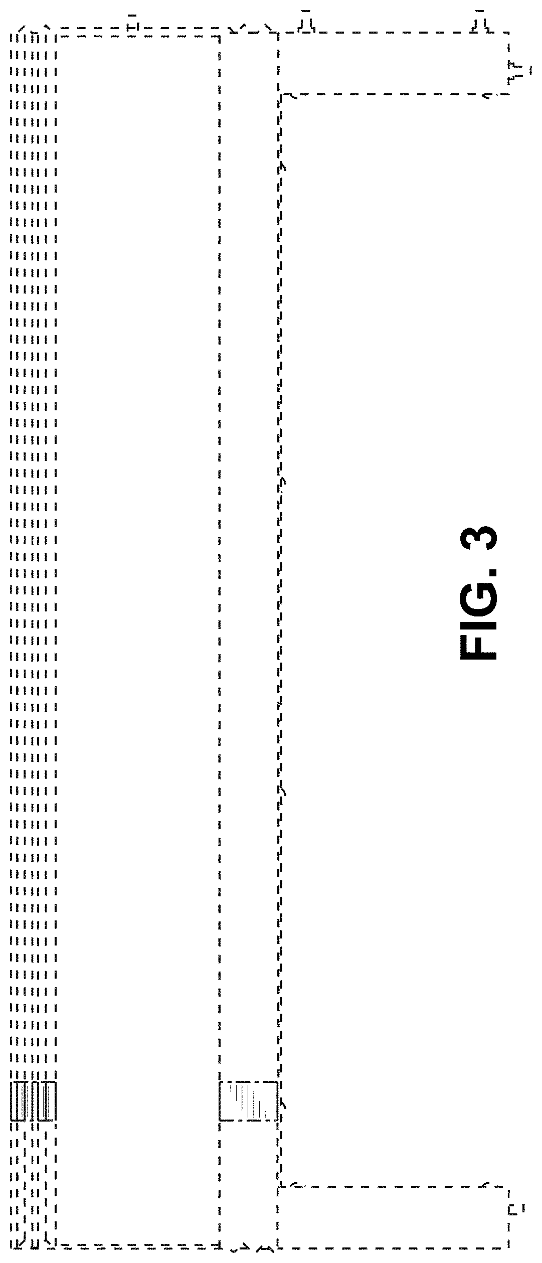
FIG. 3 is a front view thereof.
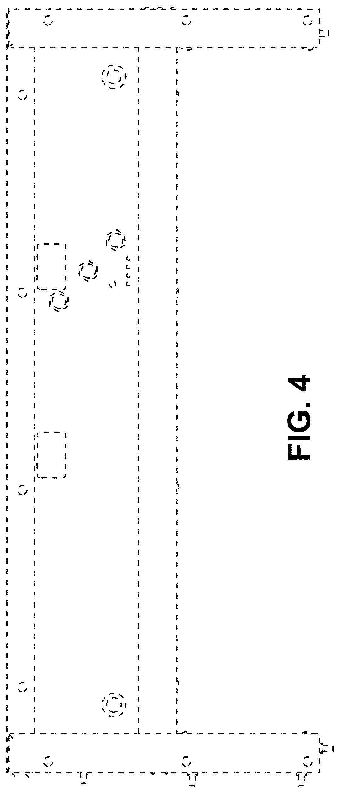
FIG. 4 is rear a view thereof.
FIG. 5 is a left view thereof.
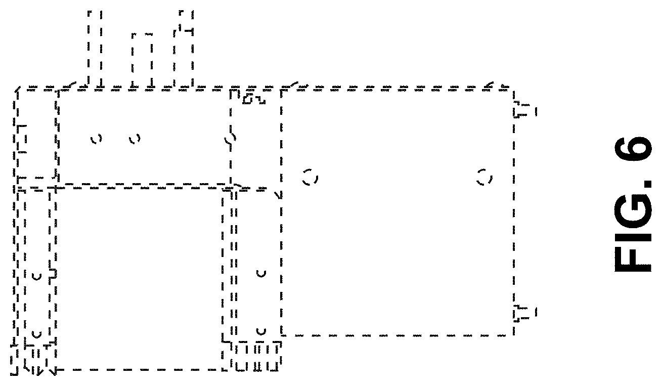
FIG. 6 is a right view thereof.
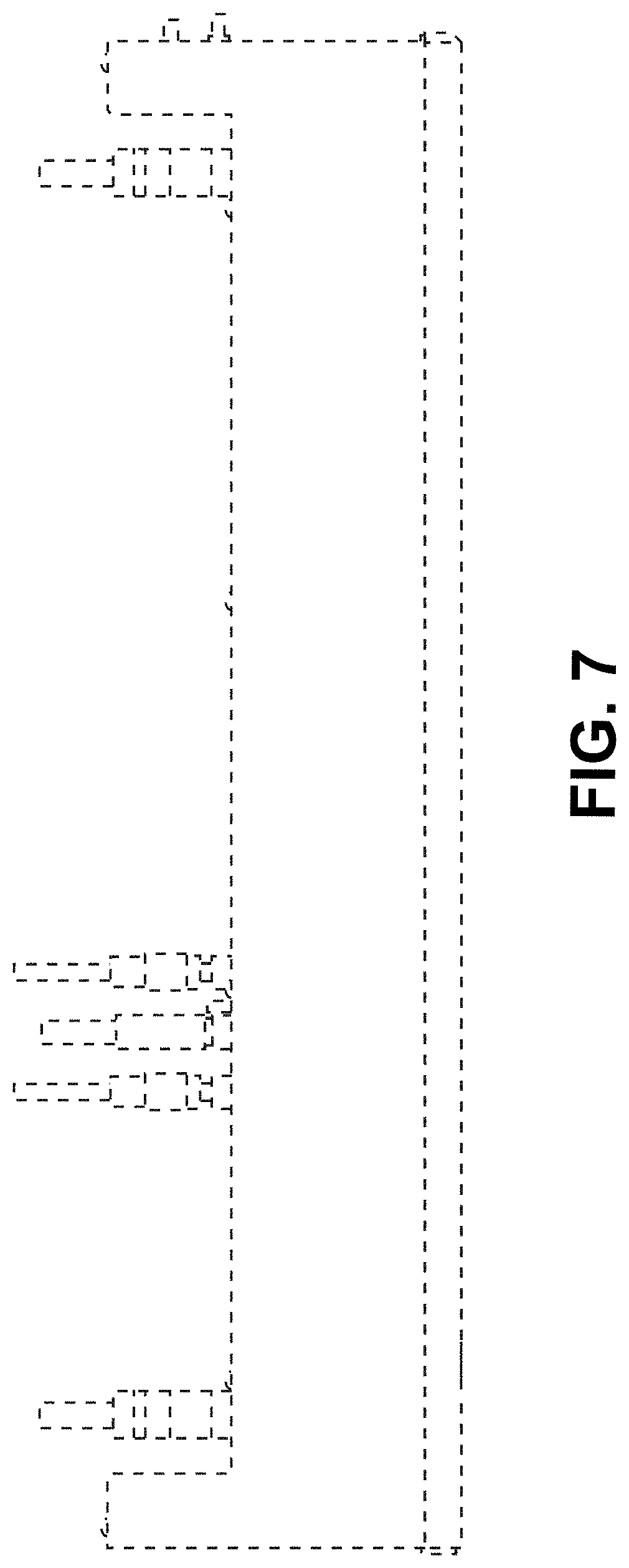
FIG. 7 is a top view thereof.
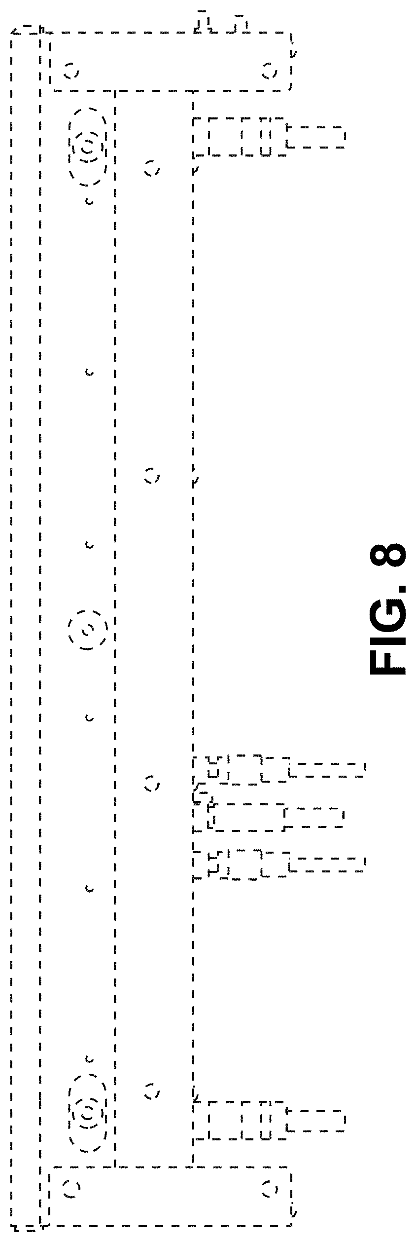
FIG. 8 is a bottom view thereof.
FIG. 9 is a front top left perspective view of a rail for a conveyor system showing our new design according to an embodiment.
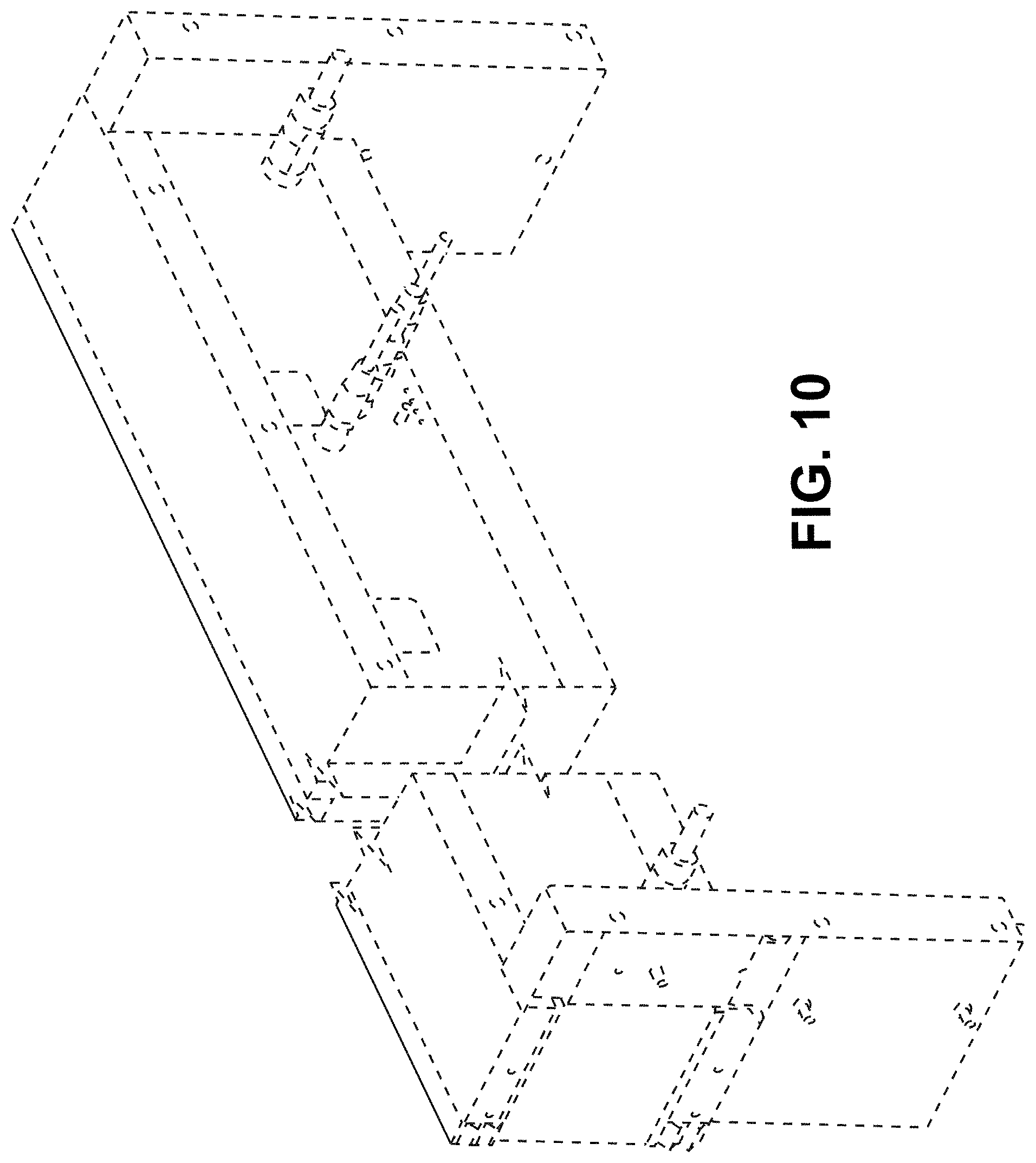
FIG. 10 is a rear bottom right perspective view thereof.
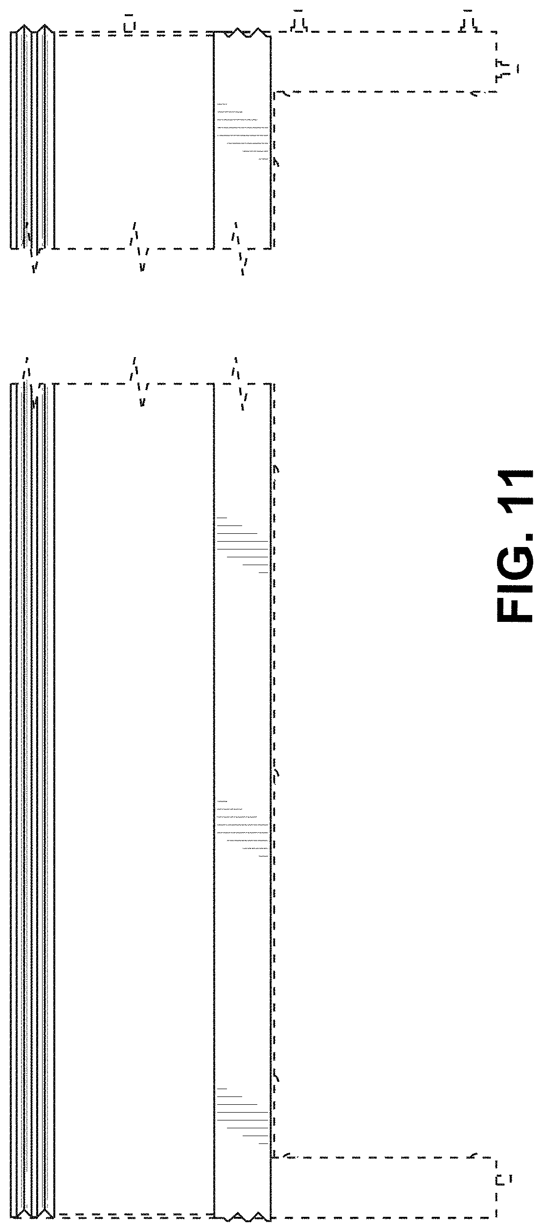
FIG. 11 is a front view thereof.
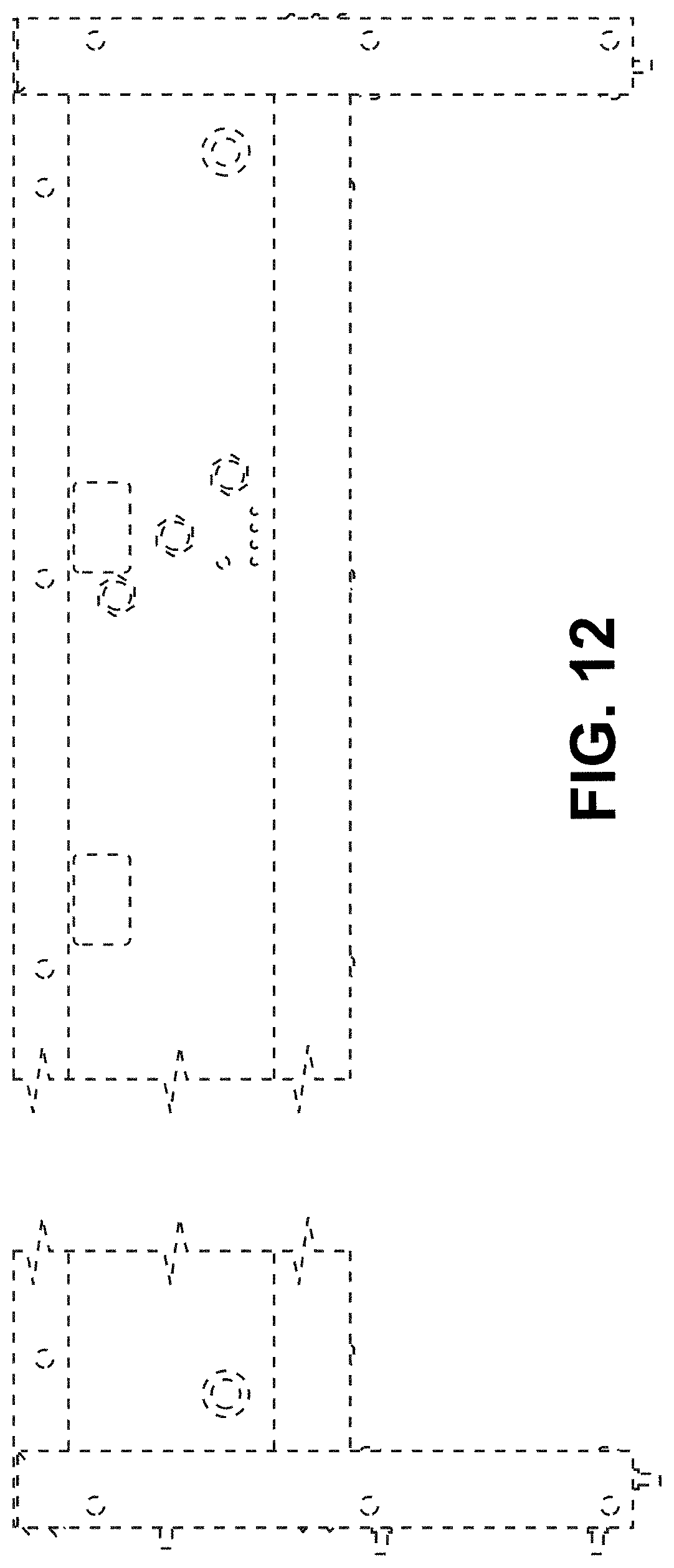
FIG. 12 is rear a view thereof.
FIG. 13 is a left view thereof.
FIG. 14 is a right view thereof.
FIG. 15 is a top view thereof.
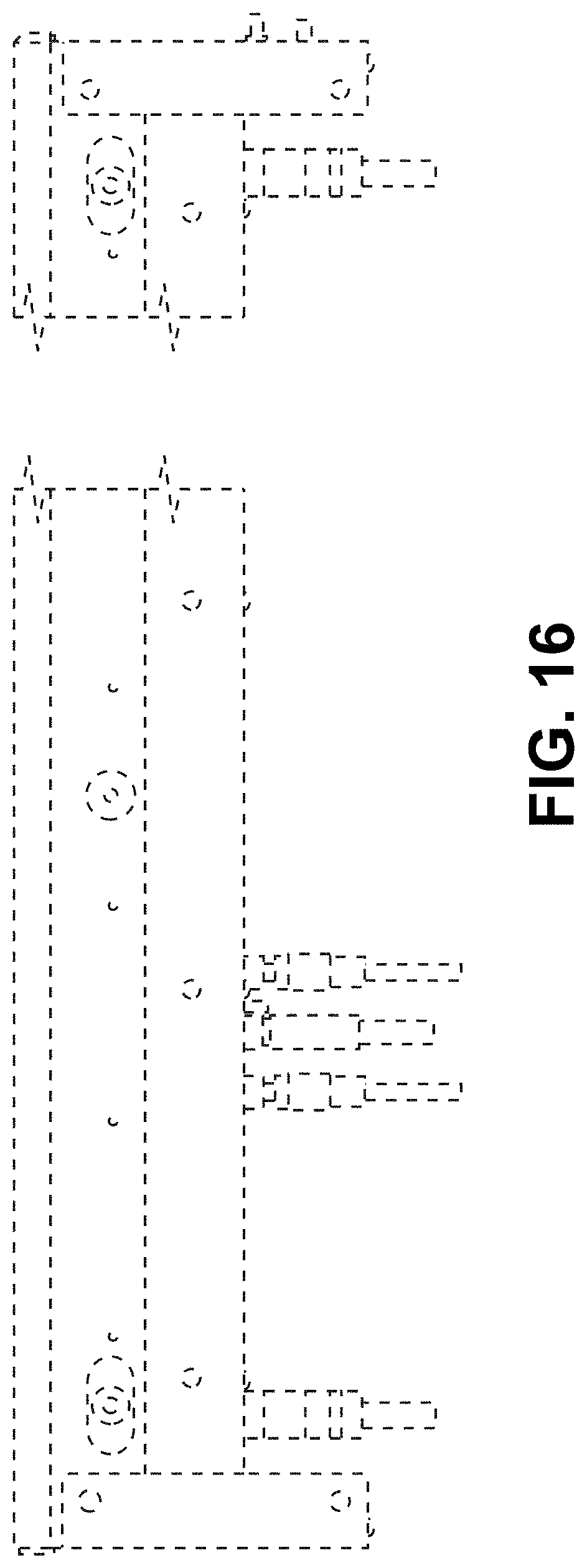
FIG. 16 is a bottom view thereof.
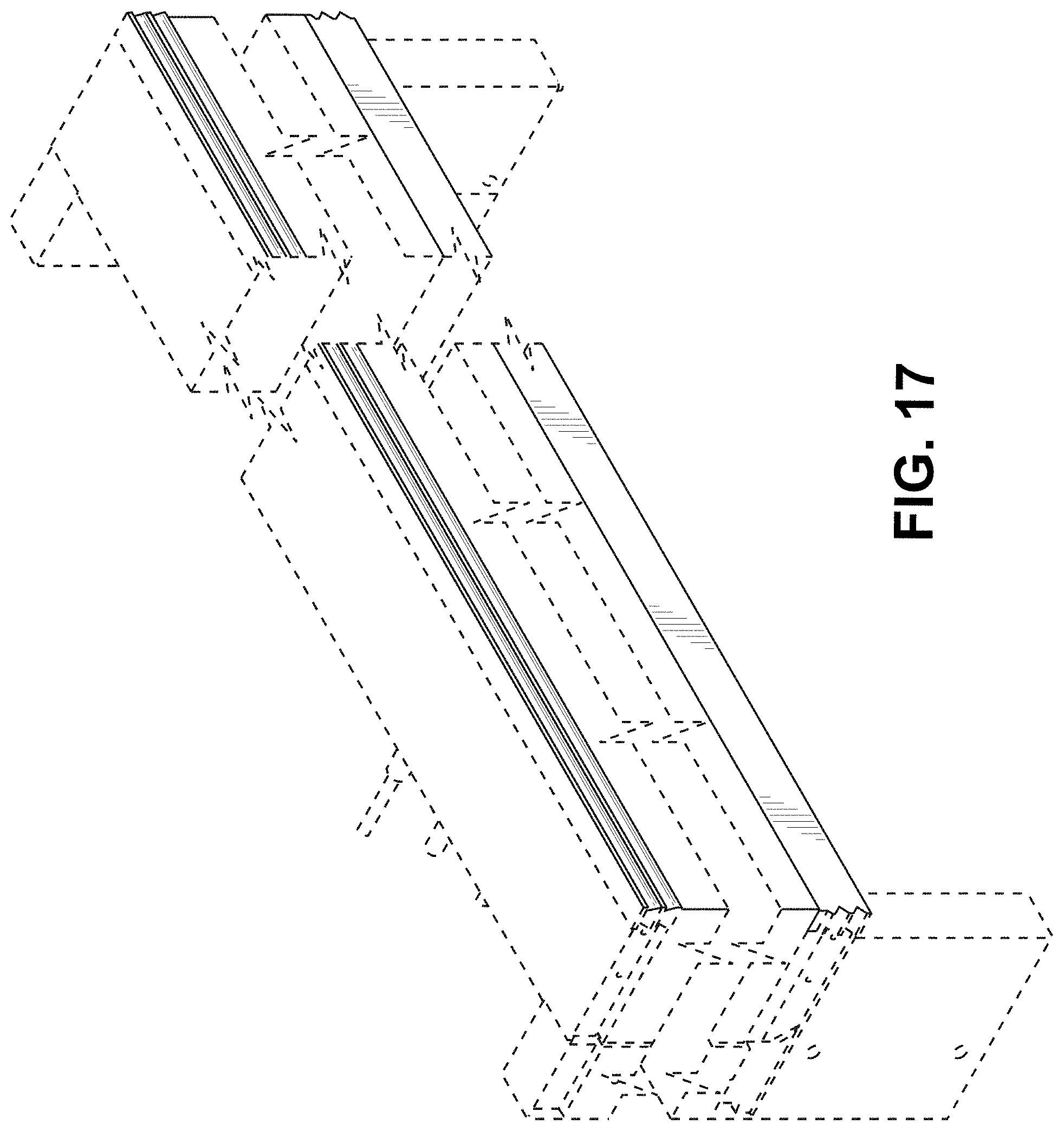
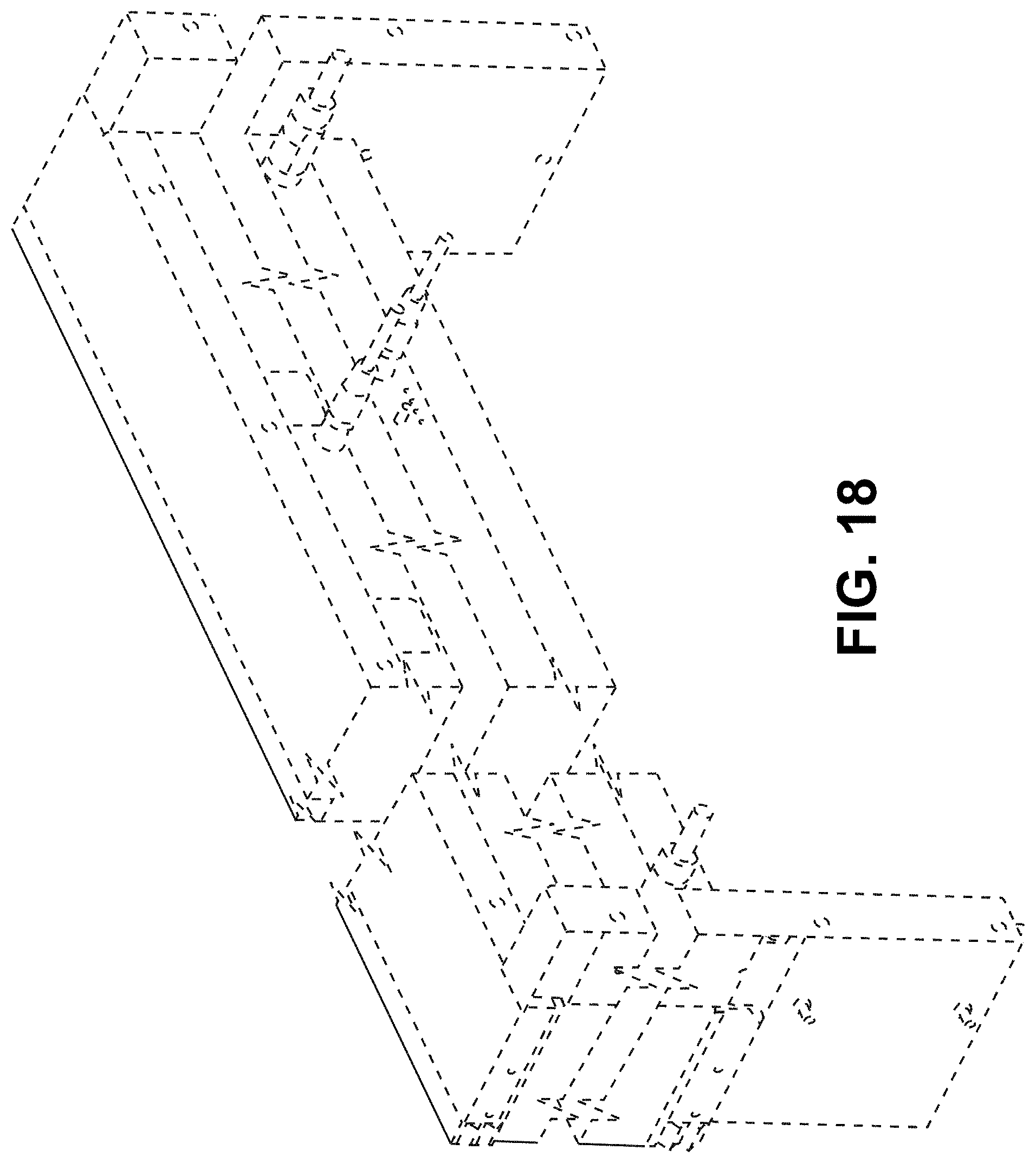
FIG. 17 is a front top left perspective view of a rail for a conveyor system showing our new design according to an embodiment.
FIG. 18 is a rear bottom right perspective view thereof.
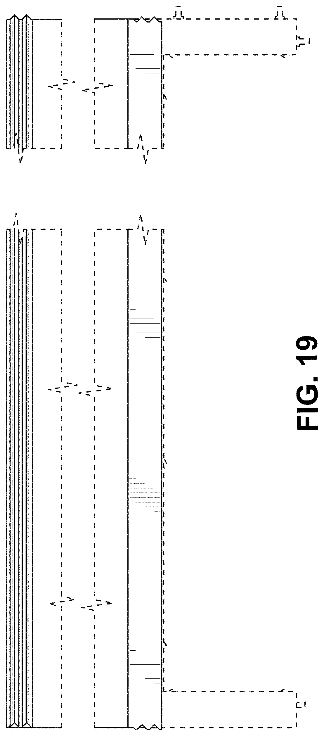
FIG. 19 is a front view thereof.
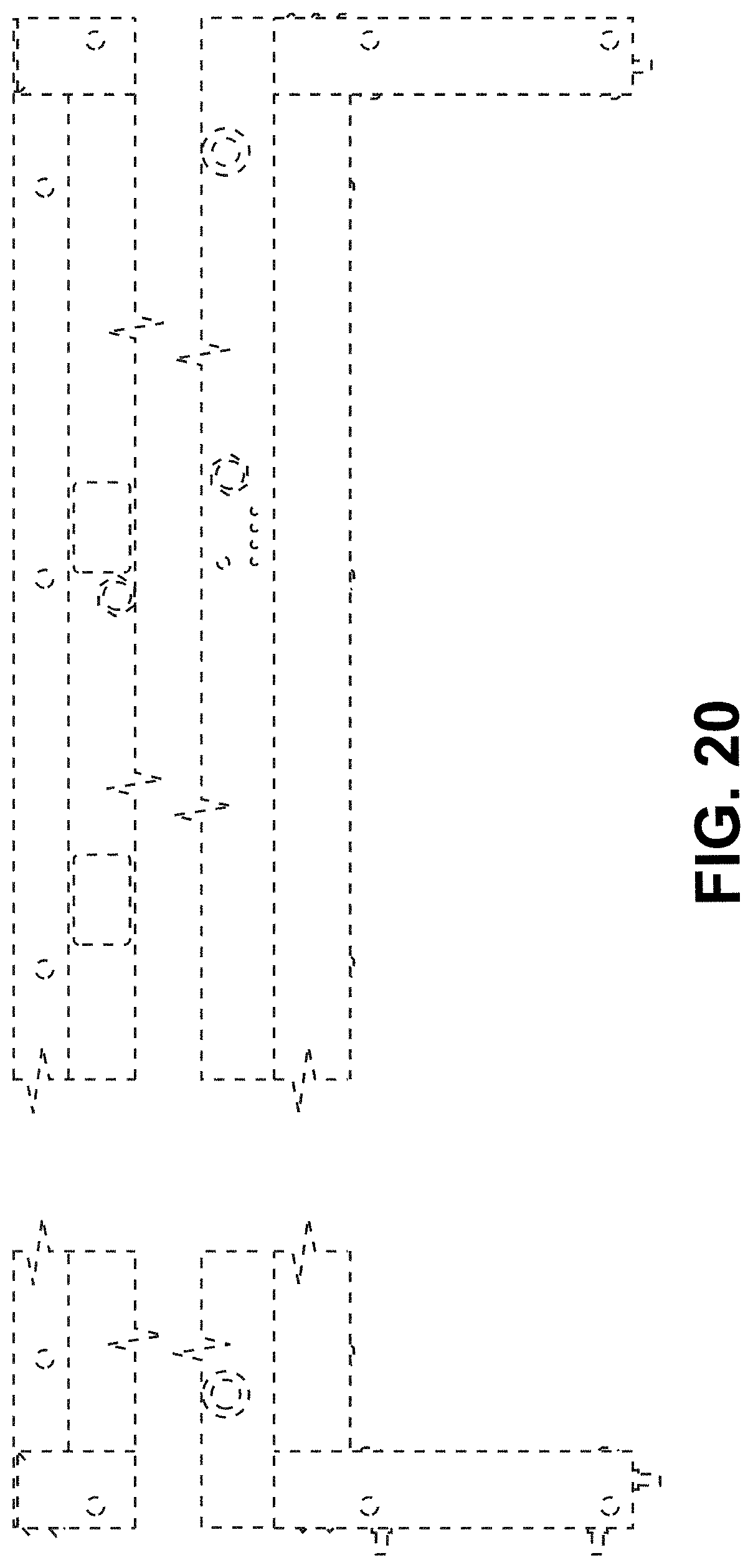
FIG. 20 is rear a view thereof.
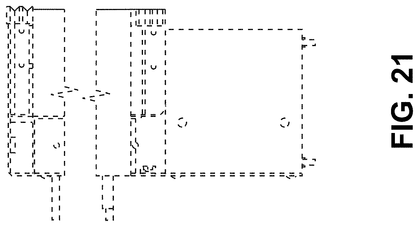
FIG. 21 is a left view thereof.
FIG. 22 is a right view thereof.
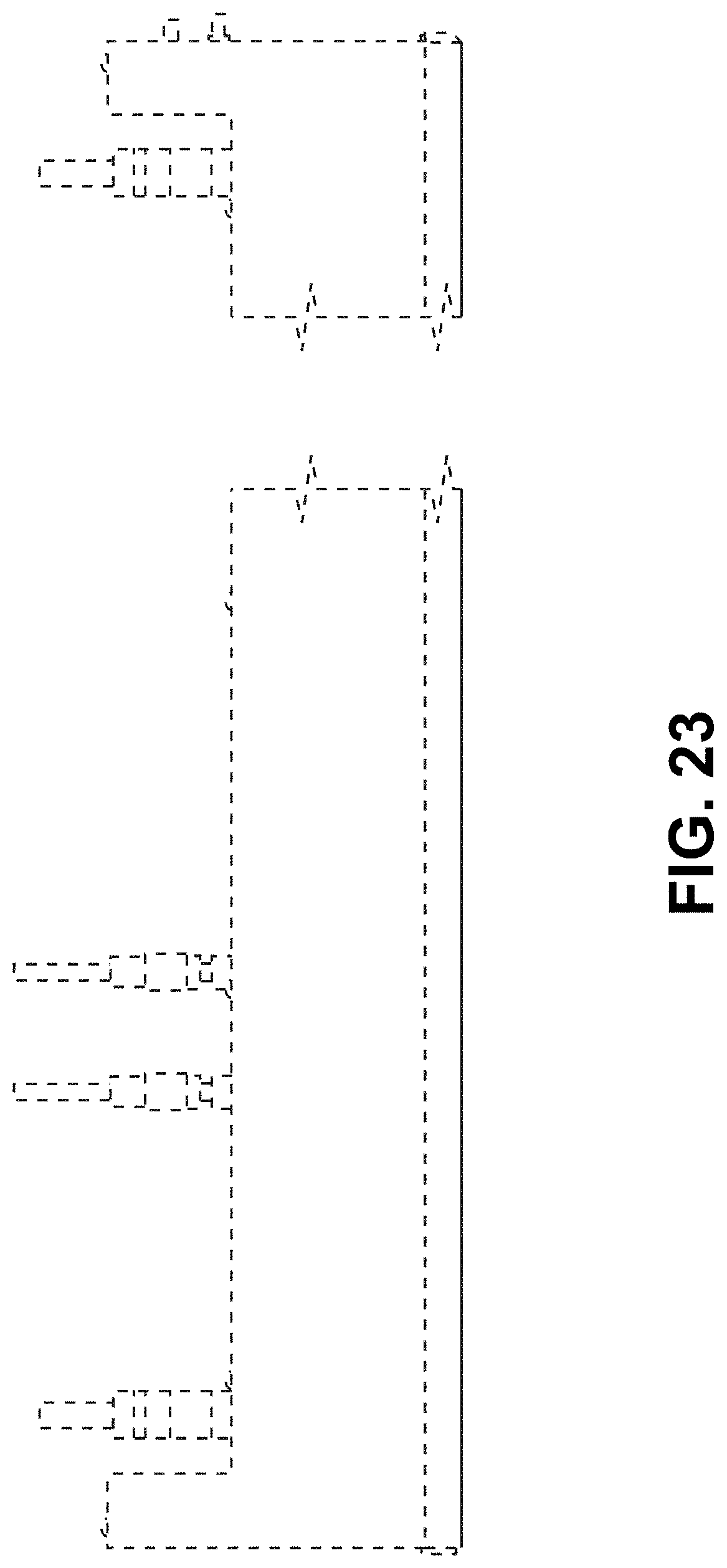
FIG. 23 is a top view thereof; and,
FIG. 24 is a bottom view thereof.
The broken lines comprising even length dashes showing the remainder of the rail for a conveyor system are unclaimed subject matter and form no part of the claimed design herein. The dot-dashed lines boundary lines form no part of the claimed design herein. The bounds of the claimed design are defined with dot-dashed boundary lines herein when a boundary does not exist at the location of the dot-dashed boundary lines in the article embodying the design. The design extends to but does not include the dot-dashed boundary lines.
The rail for a conveyor system is shown with a symbolic break in its length. The appearance of any portion of the article between the break lines form no part of the claimed design.
* * * * *
D00000
D00001
D00002
D00003
D00004
D00005
D00006
D00007
D00008
D00009
D00010
D00011
D00012
D00013

D00014

D00015

D00016
D00017
D00018
D00019
D00020
D00021
D00022

D00023
D00024

XML
uspto.report is an independent third-party trademark research tool that is not affiliated, endorsed, or sponsored by the United States Patent and Trademark Office (USPTO) or any other governmental organization. The information provided by uspto.report is based on publicly available data at the time of writing and is intended for informational purposes only.
While we strive to provide accurate and up-to-date information, we do not guarantee the accuracy, completeness, reliability, or suitability of the information displayed on this site. The use of this site is at your own risk. Any reliance you place on such information is therefore strictly at your own risk.
All official trademark data, including owner information, should be verified by visiting the official USPTO website at www.uspto.gov. This site is not intended to replace professional legal advice and should not be used as a substitute for consulting with a legal professional who is knowledgeable about trademark law.