Electronic cigarette
Li , et al.
U.S. patent number D892,397 [Application Number D/678,291] was granted by the patent office on 2020-08-04 for electronic cigarette. This patent grant is currently assigned to SHENZHEN SMOORE TECHNOLOGY LIMITED. The grantee listed for this patent is SHENZHEN SMOORE TECHNOLOGY LIMITED. Invention is credited to Kui Li, Kuan Tang, Weidong Zhou.


| United States Patent | D892,397 |
| Li , et al. | August 4, 2020 |
Electronic cigarette
Claims
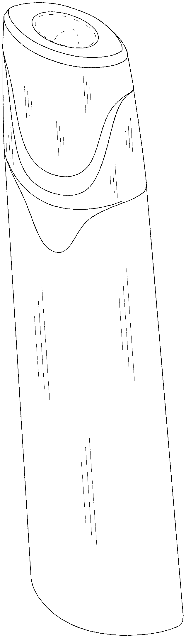
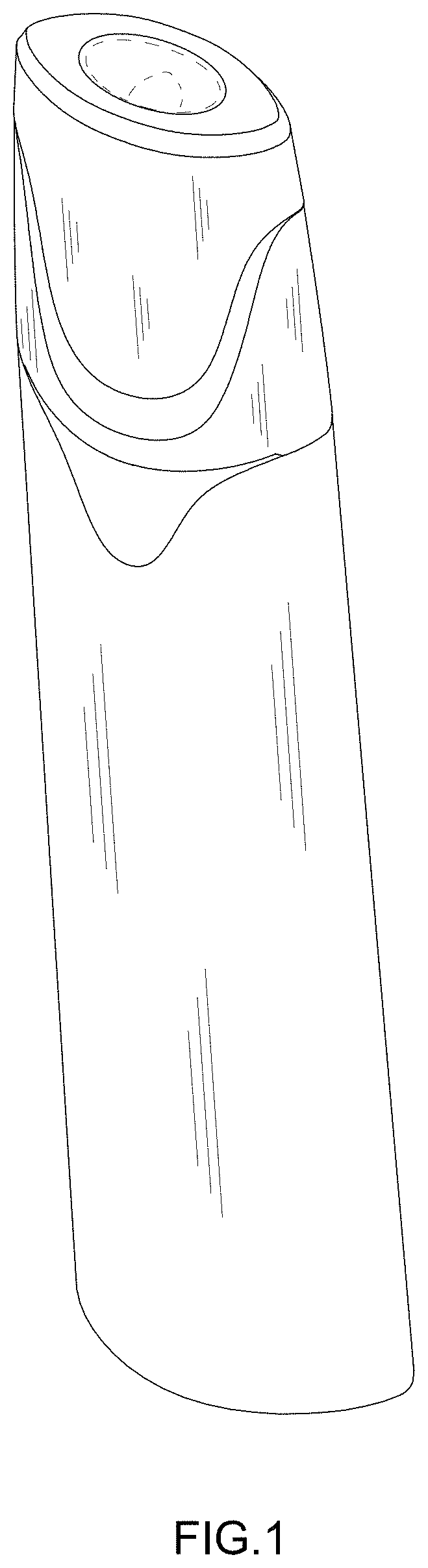
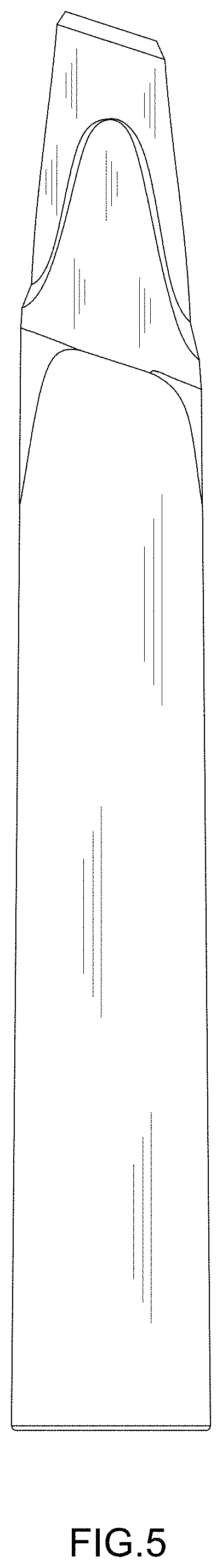
CLAIM The ornamental design for an electronic cigarette, as shown and described.
| Inventors: | Li; Kui (Shenzhen, CN), Zhou; Weidong (Shenzhen, CN), Tang; Kuan (Shenzhen, CN) | ||||||||||
|---|---|---|---|---|---|---|---|---|---|---|---|
| Applicant: |
|
||||||||||
| Assignee: | SHENZHEN SMOORE TECHNOLOGY
LIMITED (Shenzhen, CN) |
||||||||||
| Appl. No.: | D/678,291 | ||||||||||
| Filed: | January 28, 2019 |
Foreign Application Priority Data
| Jul 31, 2018 [CN] | 2018 3 0417248 | |||
| Current U.S. Class: | D27/162 |
| Current International Class: | 2702 |
| Field of Search: | ;D27/162,100,101,163-165,172,183,185-194 ;D24/110,110.5 ;128/202.21,203.12 ;131/273,274,270,191,328,329,330,360-365 |
References Cited [Referenced By]
U.S. Patent Documents
| D776337 | January 2017 | Levin |
| D799110 | October 2017 | Qiu |
| D823536 | July 2018 | Lai |
| D825834 | August 2018 | Chen |
| D827195 | August 2018 | Chen |
| D829371 | September 2018 | Durand |
| D829373 | September 2018 | Huang |
| D829980 | October 2018 | Qiu |
| D832500 | October 2018 | Qiu |
| D834246 | November 2018 | Qiu |
| D837446 | January 2019 | Durand |
| D864474 | October 2019 | Smith |
| D866064 | November 2019 | Powell |
| D874718 | February 2020 | Qiu |
| D875302 | February 2020 | Pan |
| D877976 | March 2020 | Ding |
Assistant Examiner: Tsehaye; Rebecca
Attorney, Agent or Firm: Hemisphere Law, PLLC Ma; Zhigang
Description
FIG. 1 is a first perspective view of an electronic cigarette showing our new design;
FIG. 2 is a second perspective view thereof, showing the electronic cigarette in a different position from FIG.1;
FIG. 3 is a front elevational view thereof;
FIG. 4 is a back elevational view thereof;
FIG. 5 is a left side elevational view thereof;
FIG. 6 is a right side elevational view thereof;
FIG. 7 is a top plan view thereof; and,
FIG. 8 is a bottom plan view thereof.
The broken lines immediately adjacent the shaded areas represent the bounds of the claimed design while all other broken lines are directed to environment and for illustrative purposes only; the broken lines form no part of the claimed design.
* * * * *
D00000
D00001
D00002
D00003
D00004
D00005
D00006
D00007
D00008
XML
uspto.report is an independent third-party trademark research tool that is not affiliated, endorsed, or sponsored by the United States Patent and Trademark Office (USPTO) or any other governmental organization. The information provided by uspto.report is based on publicly available data at the time of writing and is intended for informational purposes only.
While we strive to provide accurate and up-to-date information, we do not guarantee the accuracy, completeness, reliability, or suitability of the information displayed on this site. The use of this site is at your own risk. Any reliance you place on such information is therefore strictly at your own risk.
All official trademark data, including owner information, should be verified by visiting the official USPTO website at www.uspto.gov. This site is not intended to replace professional legal advice and should not be used as a substitute for consulting with a legal professional who is knowledgeable about trademark law.