Gaming machine
Schoonmaker , et al.
U.S. patent number D888,159 [Application Number D/680,138] was granted by the patent office on 2020-06-23 for gaming machine. This patent grant is currently assigned to Aristocrat Technologies Australia Pty Limited. The grantee listed for this patent is Aristocrat Technologies Australia Pty Limited. Invention is credited to Dominic DeMarco, Rena Schoonmaker.


View All Diagrams
| United States Patent | D888,159 |
| Schoonmaker , et al. | June 23, 2020 |
Gaming machine
Claims
CLAIM The ornamental design for a gaming machine, as shown and described.
| Inventors: | Schoonmaker; Rena (Las Vegas, NV), DeMarco; Dominic (Round Rock, TX) | ||||||||||
|---|---|---|---|---|---|---|---|---|---|---|---|
| Applicant: |
|
||||||||||
| Assignee: | Aristocrat Technologies Australia
Pty Limited (North Ryde, AU) |
||||||||||
| Appl. No.: | D/680,138 | ||||||||||
| Filed: | February 13, 2019 |
Related U.S. Patent Documents
| Application Number | Filing Date | Patent Number | Issue Date | ||
|---|---|---|---|---|---|
| 29619823 | Oct 2, 2017 | D846649 | |||
| Current U.S. Class: | D21/369 |
| Current International Class: | 2103 |
| Field of Search: | ;D14/126,127,133,305,307,340,336,371,374,432,439,450 ;D21/324,325,369,370,371,385 |
References Cited [Referenced By]
U.S. Patent Documents
| 3780286 | December 1973 | Alexieff et al. |
| D295193 | April 1988 | Visocky et al. |
| D372314 | July 1996 | Delman |
| D391773 | March 1998 | Zaidman et al. |
| D392468 | March 1998 | O'Reilly |
| D405976 | February 1999 | Beall |
| D411582 | June 1999 | Muraki et al. |
| D503435 | March 2005 | Morrison |
| D503436 | March 2005 | Morrison |
| D510959 | October 2005 | Morrison |
| D523249 | June 2006 | Hoernig |
| D544922 | June 2007 | Shaffer |
| D572024 | July 2008 | Shapiro |
| D594510 | June 2009 | Sappington et al. |
| D602996 | October 2009 | Takeuchi |
| D613338 | April 2010 | Marukos |
| D636187 | April 2011 | Kim et al. |
| D636188 | April 2011 | Kim et al. |
| D639568 | June 2011 | Lee et al. |
| D642385 | August 2011 | Lee et al. |
| D676430 | February 2013 | Blaser |
| 8382572 | February 2013 | Hoffman et al. |
| 8491385 | July 2013 | Miodunski |
| D715364 | October 2014 | Wudtke |
| D732113 | June 2015 | Estep |
| D732114 | June 2015 | Estep |
| D740571 | October 2015 | Gorham |
| D740888 | October 2015 | DePalma et al. |
| D790232 | June 2017 | Santos |
| D806690 | January 2018 | Schimon |
| 10013061 | July 2018 | Froy |
| 10013845 | July 2018 | Froy et al. |
| D832356 | October 2018 | Castro et al. |
| D846649 | April 2019 | Schoonmaker |
| D868714 | December 2019 | Hodgson |
| D868718 | December 2019 | Hodgson |
| D868719 | December 2019 | Hodgson |
| 10506730 | December 2019 | Wand |
| D877810 | March 2020 | Nelson |
| D880604 | April 2020 | Olive |
| 2018/0040203 | February 2018 | Winters et al. |
| 2018/0082545 | March 2018 | Winters et al. |
| 2019/0102971 | April 2019 | Schoonmaker |
Assistant Examiner: Maharajh; Michael A
Attorney, Agent or Firm: McAndrews, Held & Malloy, Ltd.
Description
FIG. 1 is a front perspective view of a gaming machine showing our new design according to a first embodiment;
FIG. 2 is a front elevation view thereof;
FIG. 3 is a rear elevation view thereof;
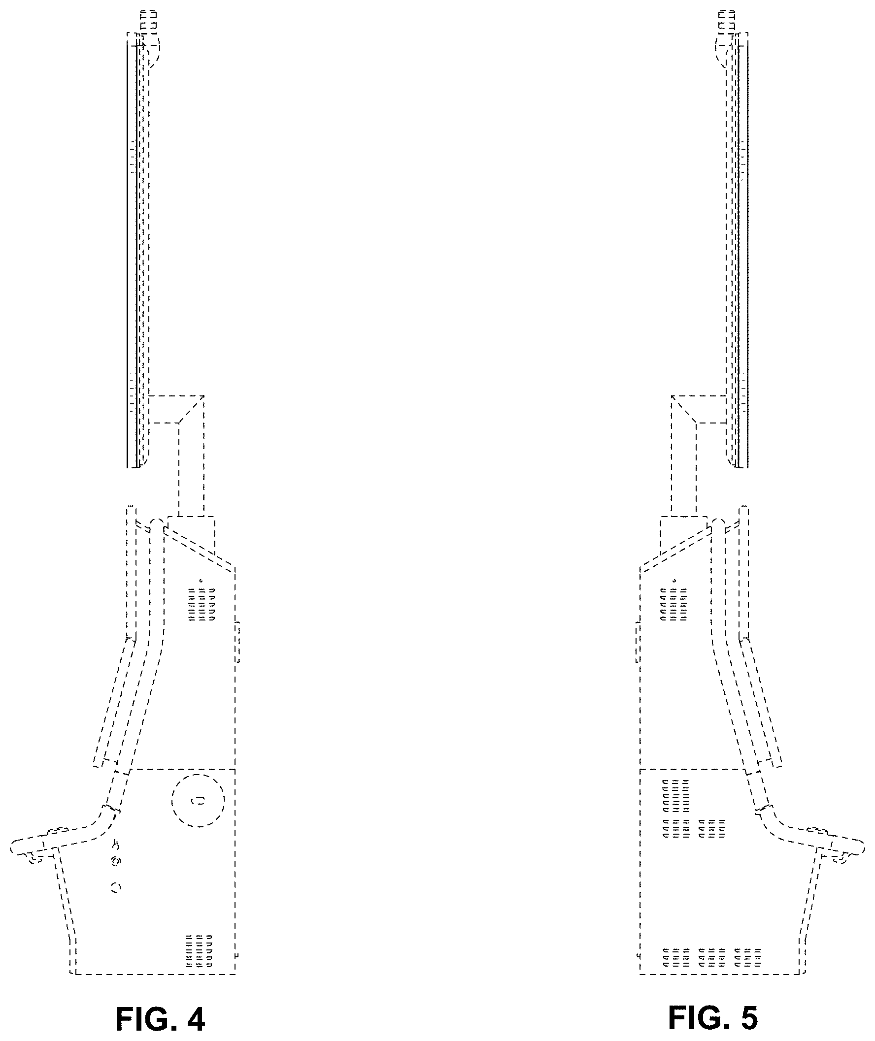
FIG. 4 is a right side elevation view thereof;
FIG. 5 is a left side elevation view thereof;
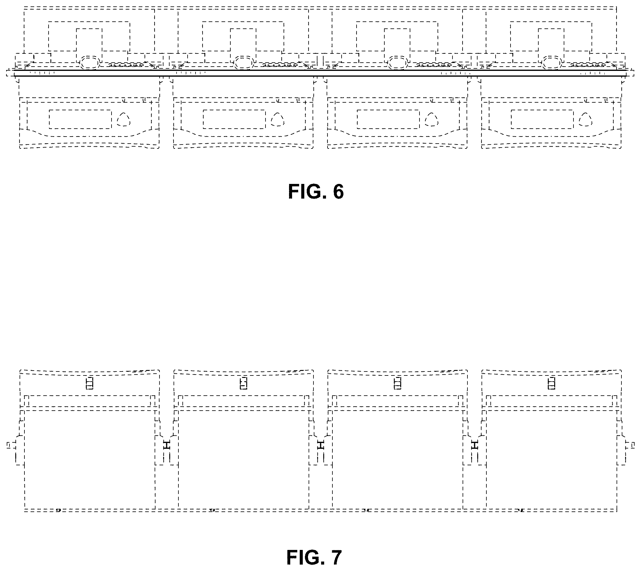
FIG. 6 is a top plan view thereof;
FIG. 7 is a bottom plan view thereof;
FIG. 8 is another front elevation view thereof, showing our new design in an illuminated state;
FIG. 9 is a front perspective view of a gaming machine showing our new design according to a second embodiment;
FIG. 10 is a front elevation view thereof;
FIG. 11 is a rear elevation view thereof;
FIG. 12 is a right side elevation view thereof;
FIG. 13 is a left side elevation view thereof;
FIG. 14 is a top plan view thereof;
FIG. 15 is a bottom plan view thereof; and,
FIG. 16 is another front elevation view thereof, showing our new design in an illuminated state.
The dashed broken lines in the drawings illustrate portions of the gaming machine that form no part of the claimed design.
The radiating lines in FIGS. 8 and 16 represent the glowing visual effect created by light emanating from the light ring surrounding the upper displays of the gaming machine.
* * * * *
D00000
D00001
D00002
D00003
D00004
D00005
D00006
D00007
D00008
D00009
D00010
D00011
D00012

XML
uspto.report is an independent third-party trademark research tool that is not affiliated, endorsed, or sponsored by the United States Patent and Trademark Office (USPTO) or any other governmental organization. The information provided by uspto.report is based on publicly available data at the time of writing and is intended for informational purposes only.
While we strive to provide accurate and up-to-date information, we do not guarantee the accuracy, completeness, reliability, or suitability of the information displayed on this site. The use of this site is at your own risk. Any reliance you place on such information is therefore strictly at your own risk.
All official trademark data, including owner information, should be verified by visiting the official USPTO website at www.uspto.gov. This site is not intended to replace professional legal advice and should not be used as a substitute for consulting with a legal professional who is knowledgeable about trademark law.