TV mount bracket
Pei
U.S. patent number D888,027 [Application Number D/676,456] was granted by the patent office on 2020-06-23 for tv mount bracket. This patent grant is currently assigned to Xubo Pei. The grantee listed for this patent is Xubo Pei. Invention is credited to Xubo Pei.


| United States Patent | D888,027 |
| Pei | June 23, 2020 |
TV mount bracket
Claims
CLAIM The ornamental design for a TV mount bracket, as shown and described.
| Inventors: | Pei; Xubo (Shenzhen, CN) | ||||||||||
|---|---|---|---|---|---|---|---|---|---|---|---|
| Applicant: |
|
||||||||||
| Assignee: | Pei; Xubo (Shenzhen,
CN) |
||||||||||
| Appl. No.: | D/676,456 | ||||||||||
| Filed: | January 11, 2019 |
Foreign Application Priority Data
| Dec 13, 2018 [CN] | 2018 3 0723771 | |||
| Current U.S. Class: | D14/239; D8/349; D8/363 |
| Current International Class: | 1403 |
| Field of Search: | ;D8/349,363 ;D14/239 |
References Cited [Referenced By]
U.S. Patent Documents
| D624061 | September 2010 | Smith |
| D643421 | August 2011 | Russell |
| D650373 | December 2011 | Stemple |
| D811375 | February 2018 | Pei |
| D811376 | February 2018 | Pei |
| D836617 | December 2018 | Shu |
| D842283 | March 2019 | Pei |
| D848989 | May 2019 | Pei |
| D848990 | May 2019 | Pei |
| D852790 | July 2019 | Pei |
| D858493 | September 2019 | Pei |
| 2019/0390817 | December 2019 | Pei |
Other References
|
Full Motion TV Wall Mount for TVs 47''-84'', posted as early as Nov. 30, 2019, [online], [retrieved Mar. 5, 2020]. Retrieved from internet, https://www.walmart.com/ip/ONN-Full-Motion-TV-Wall-Mount-for-TVs-47-84/14- 5581487?wmlspartner=wlpa&selectedSellerId=0&adid=222222222273%E2%80%A6 (Year: 2019). cited by examiner. |
Primary Examiner: Fox; Barbara
Assistant Examiner: Kwon; Aram
Attorney, Agent or Firm: Dave Law Group LLC Dave; Raj S.
Description
FIG. 1 is a front view of a TV mount bracket showing the new design;
FIG. 2 is a rear view thereof;
FIG. 3 is a left side view thereof;
FIG. 4 is a right side view thereof;
FIG. 5 is a top side view thereof;
FIG. 6 is a bottom side view thereof;
FIG. 7 is a perspective view of the front, top and left side thereof;
FIG. 8 is a perspective view of the front, top and left side thereof, shown in a partially open configuration; and,
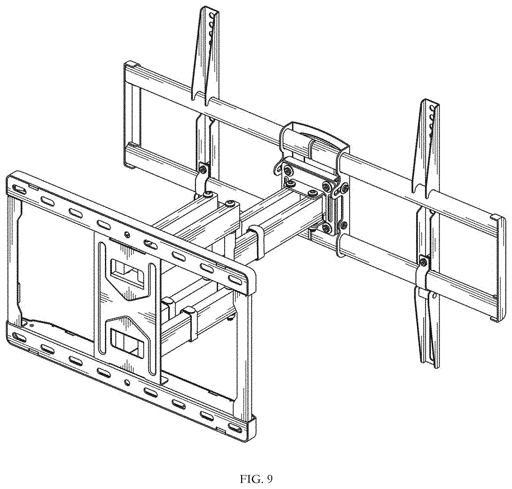
FIG. 9 is a perspective view of the rear, top and right side thereof, in a fully open configuration.
The shade lines in the Figures show contour and not surface ornamentation.
* * * * *
References
D00000
D00001
D00002
D00003
D00004
D00005
D00006
XML
uspto.report is an independent third-party trademark research tool that is not affiliated, endorsed, or sponsored by the United States Patent and Trademark Office (USPTO) or any other governmental organization. The information provided by uspto.report is based on publicly available data at the time of writing and is intended for informational purposes only.
While we strive to provide accurate and up-to-date information, we do not guarantee the accuracy, completeness, reliability, or suitability of the information displayed on this site. The use of this site is at your own risk. Any reliance you place on such information is therefore strictly at your own risk.
All official trademark data, including owner information, should be verified by visiting the official USPTO website at www.uspto.gov. This site is not intended to replace professional legal advice and should not be used as a substitute for consulting with a legal professional who is knowledgeable about trademark law.